

Page 1
TempScan & MultiScan Quick Start
Before you get started
Verify that you have the following items.
Step 1 - Install Software IMPORTANT ! Software must be installed first!
1. Close all running applications on the host PC.
3. Click the <ENTER SETUP> button.
Note: If you are downloading software from our website, follow instructions provided there.
4. From the hardware selection screen [which follows a licensing agreement], select the TempScan/1100 or MultiScan/1200, as
applicable; then follow the on-screen instructions.
NOTE: To enable all ChartView features: (a) From ChartView’s main window, open the File pull-down menu,
(b) select Authorization, (c) enter C3523DFA6C0A in the dialog box and apply the code.
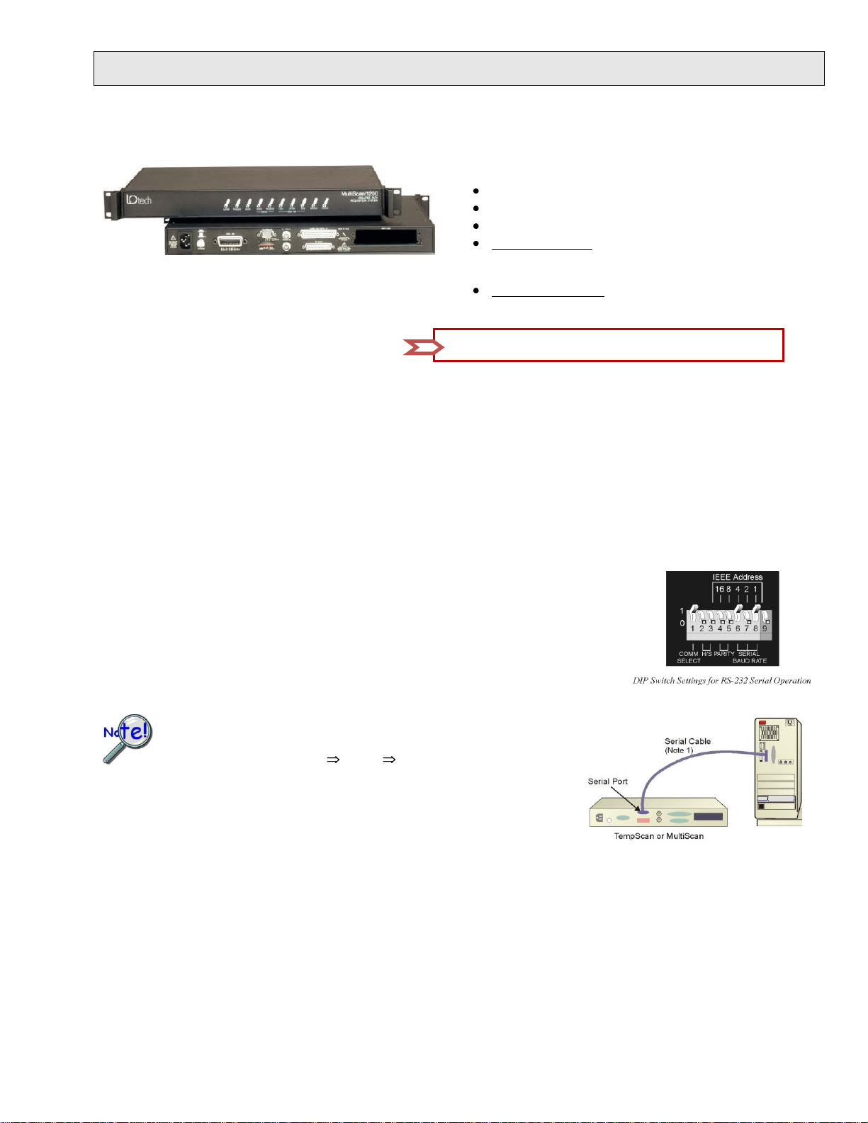
Prior to making a serial connection, make sure that the host PC’s serial
(COM) port is available and properly configured to match the DIP
switch setting in Step 2. Do this by navigating from the Windows
Desktop, i. e., Control Panel System Device Manager tab, then
clicking on Ports (COM & LPT).
Using a serial communications cable, connect the TempScan [or MultiScan] to the host
PC by one (and only one) of the following methods:
USB
Use only
one of
these 3
connection
options.
RS-232
Requires a DB9F to DB9F serial communication cable. Connect the cable from the TempScan [or MultiScan]
Serial Port to a RS-232 Serial Port on the host PC.
RS-422
Requires a DB9F to DB25F serial communication cable. Connect the DB9F to the TempScan [or MultiScan]
Serial Port. Connect the DB25F to an RS-422 Serial Port on the host PC.
High-Speed Temperature & Voltage Scanning Instruments
TempScan/1100 or MultiScan/1200
Data Acquisition CD (8.1.2 or higher)
Monitor: SVGA, 1024 x 768 screen resolution
Windows XP users:
2. Insert the Data Acquisition CD (8.1.2 or higher) into your CD-ROM drive and wait for the PC to auto-run. An Opening
Screen will appear. If AutoRun is disabled: (a) right click Windows Start menu, (b) select Explore; and (c) double-click
MasterSetup.exe. As an alternative to using the CD, you can download software from www.mccdaq.com/software.
PC with Intel™ Pentium [or equivalent]; 1 GHz
512 MB memory; 10 GB disk space
Windows Vista users:
PC must be Windows Vista Premium Ready
Step 2 – Check Hardware
1. Verify that the voltage stated on the sticker [near the power switch] matches the voltage
of your intended AC power supply. If you need to change the voltage, refer to your
user’s manual.
2. Check the DIP switch, located on the rear panel. Your user’s manual discusses setting
options.
Step 3 - Connect to the Host PC
Requires an adapter kit. To connect the TempScan [or MultiScan] to a USB port you will need a RS-232 to
USB Interface Adapter Kit p/n CA-232-USB-KIT (available from MCC). Refer to the associated Quick Start
document (QS RS-232_to_USB_Interface.pdf) for a list of the kit’s contents and for RS-232 to USB conversion
instructions. The pdf is included on your Data Acquisition CD (rev 8.1.2 and higher).
Note 1: Measurement Computing offers a CA-47 three-connector serial communications cable. The single cable has two DB9F connectors
and one DB25F connector. Note that the CA-232-USB-KIT includes a CA-47 cable.
446-0940, rev 4.0 324602C-01
Page 2

324602C-01
446-0940 rev 4.0
Step 4 – Connect Input Signals
CAUTION! Use approved ESD precautions, including static-free work area and grounded wrist strap, when
handling circuit boards and electronic components. Failure to do so could cause equipment damage due to
electrostatic discharge.
When making differential voltage measurements, you should ensure that one of the common terminal blocks is
connected to the common of the unit being measured.
CAUTION! TempScan/1100 scanning cards are designed for and supported only by the TempScan/1100 master
unit. MultiScan/1200 scanning cards are designed for and supported only by the MultiScan/1200 master unit. Use
of a wrong card can cause operating errors and possibly damage equipment.
Do not connect the power to any devices that are connected to the scanning card inputs until after the scanning
cards have been properly installed in the scan device.
Reference Notes:
Documents are automatically installed onto your PC’s hard-drive as a part of product support at the time of software
installation. The default location is the Programs group. It can be accessed via the Windows Desktop Start Menu.
Documents can also be read directly from the data acquisition CD.
*324602C-01*
Insert the appropriate wires into the selected screw-terminal sockets of your scanning card to make the channel input connections. Each
scanning card contains screw-terminal blocks for making quick input connections. Labeling is provided on the card for channel
identification. Note that tie-wraps can be used in conjunction with the card’s tie-down holes to provide strain relief and to keep the
channel wires organized.
1. When the channel input connections on the scanning card are ready, make sure that the POWER pushbutton on the scan
device (TempScan or MultiScan) is in the "OFF" position (extended out).
2. Plug the CA-1 power cable into the unit and then into the proper AC power outlet. Do not connect the power to any
devices that are connected to the scanning card inputs at this time.
3. Install the scanning card into the INPUT CARD slot of the unit.
4. After the scanning card is installed, connect the power lines to the devices that are connected to the scanning card inputs.
Then make other connections as applicable to your system.
Step 5 – Apply Power to the System
1. Turn on the host PC.
2. Turn on the scan device (TempScan/1100 or MultiScan/1200) by pushing in the POWER pushbutton.
3. Turn on any applicable devices that are connected to the scanning card inputs.
Step 6 – Start ChartView, Configure the System, and Collect Data
1. From Windows desktop, double-click on the ChartView icon.
2. Choose the <Select Device> button.
3. Select RS-232 and click <OK>. Click <OK> again.
Note: For changes from default, refer to the user’s manual.
4. In the Automatic Chart Creation portion of the window, click <Create Charts> to automatically create a chart display configuration.
Note that a Channel and Alarm Setup dialog box will appear above the main window.
5. Click the <Make All Channels Active> button to enable all channels.
6. Click the <Enable SpreadSheet Reading> button. Click <OK>.
7. Push the <Start Charts and Indicators> button. Charts will begin scrolling.
Measurement Computing Corp., 10 Commerce Way, Norton, MA 02766
phone: (508) 946-5100 e-mail: info@
mccdaq.com
www.mccdaq.com
 Loading...