

Page 1

STLITE-CPCI-8R(+)
STLITE-CPCI-16R(+)
Satellite Series
CPCI Expansion System
User’s Manual
Copyright February, 2001
Page 2

LIFETIME WARRANTY
Every hardware product manufactured by Measurement Computing Corp. is warranted against defects in
materials or workmanship for the life of the product, to the original purchaser. Any products found to be
defective will be repaired or replaced promptly.
LIFETIME HARSH ENVIRONMENT WARRANTY
TM
Any Measurement Computing Corp. product which is damaged due to misuse may be replaced for only 50% of
the current price. I/O boards face some harsh environments, some harsher than the boards are designed to
withstand. When that happens, just return the board with an order for its replacement at only 50% of the list
price. Measurement Computing Corp. does not need to profit from your misfortune. We honor this warranty for
any manufacture’s board that we have a replacement for!
30 DAY MONEY-BACK GUARANTEE
Any Measurement Computing Corp. product may be returned within 30 days of purchase for a full refund of the
price paid. If you are not satisfied, or chose the wrong product by mistake, you do not have to keep it. Please call
for a RMA number first. No credits or returns are accepted without a copy of the original invoice. Certain
software products have a repackaging fee.
These warranties are in lieu of all other warranties, expressed or implied, including any implied warranty of
merchantability or fitness for a particular application. The remedies provided herein are the buyer’s sole and
exclusive remedies. Neither Measurement Computing Corp., nor its employees shall be liable for any direct or
indirect, special, incidental or consequential damage arising from the use of its products, even if Measurement
Computing Corp. has been notified in advance of the possibility of such damages.
MEGA-FIFO, the CIO prefix to data acquisition board model numbers, the PCM prefix to data acquisition board
model numbers, PCM-DAS08, PCM-D24C3, PCM-DAC02, PCM-COM422, PCM-COM485, PCM-DMM,
PCM-DAS16D/12, PCM-DAS16S/12, PCM-DAS16D/16, PCM-DAS16S/16, CPCI-DAS6402/16, Universal
Library, InstaCal, Harsh Environment Warranty and Measurement Computing Corp. are registered trademarks
of Measurement Computing Corp.
IBM, PC, and PC/AT are trademarks of International Business Machines Corp. Windows is a trademark of
Microsoft Corp. All other trademarks are the property of their respective owners.
Information furnished by Measurement Computing Corp. is believed to be accurate and reliable. However, no
responsibility is assumed by Measurement Computing Corp. neither for its use; nor for any infringements of
patents or other rights of third parties, which may result from its use. No license is granted by implication or
otherwise under any patent or copyrights of Measurement Computing Corporation.
All rights reserved. No part of this publication may be reproduced, stored in a retrieval system, or transmitted, in
any form by any means, electronic, mechanical, by photocopying, recording or otherwise without the prior
written permission of Measurement Computing Corporation.
Notice
Measurement Computing Corp. does not authorize any Measurement Computing Corp.
product for use in life support systems and/or devices without the written approval of the
President of Measurement Computing Corp. Life support devices/systems are devices or
systems which, a) are intended for surgical implantation into the body, or b) support or sustain
life and whose failure to perform can be reasonably expected to result in injury. Measurement
Computing Corp. products are not designed with the components required, and are not
subject to the testing required to ensure a level of reliability suitable for the treatment and
diagnosis of people.
HM STLITE-CPCI-##x.doc
ii
Page 3

Table of Contents
1. INTRODUCTION...............................................................................................................................1
2. COMPONENTS – STANDARD SYSTEM......................................................................................2
2.1 CPCI EXPANSION MOTHERBOARD.........................................................................................2
2.2 HOST BRIDGE CARD: STLITE-PCI-HOST; STLITE-CPCI-HOST ..........................................2
2.3 POWER SUPPLY...........................................................................................................................2
2.4 EXPANSION CABLE....................................................................................................................3
2.5 CABINET........................................................................................................................................3
3. INSTALLATION & START-UP – STANDARD SYSTEM...........................................................3
3.1 PRELIMINARY INSTRUCTION..................................................................................................3
3.2 HOST BRIDGE CARD INSTALLATION ....................................................................................3
3.3 CARD INSTALLATION - EXPANSION CHASSIS ....................................................................3
3.4 CPCI EXPANSION CABLE INSTALLATION............................................................................4
3.5 CPCI CARD INSTALLATION......................................................................................................4
3.6 CABLE INSTALLATION..............................................................................................................4
3.7 FINAL INSTALLATION CHECK.................................................................................................4
4. POWERING-UP .................................................................................................................................5
4.1 SEQUENCE FOR APPLYING POWER........................................................................................5
4.2 POWERING DOWN ......................................................................................................................5
5. MULTIPLE CHASSIS INSTALLATION .......................................................................................5
5.1 INTRODUCTION...........................................................................................................................5
5.2 DAISY-CHAIN CONFIGURATION.............................................................................................5
5.3 FAN-OUT CONFIGURATION......................................................................................................7
5.4 EXTENDED DAISY CHAIN CONFIGURATION.......................................................................8
5.5 CPCI CARD CONFLICTS.............................................................................................................8
5.6 BIOS/FIRMWARE REQUIREMENTS .........................................................................................8
6. SATELLITE
6.1 INSTALLATION............................................................................................................................9
6.2 USING THE
WATCH DOG TIMER AND ALARM..............................................................................................11
MONITOR SOFTWARE INSTALLATION AND USE..........................................9
SATELLITE
MONITOR PROGRAM.......................................................................9
6.4 EXAMPLE PROGRAMS.............................................................................................................12
7. REGISTER MAP..............................................................................................................................13
7.1 REGISTER MAP..........................................................................................................................13
7.2 EXPANSION BOARD 21150 BRIDGE REGISTERS................................................................13
iii
Page 4

7.3 SATELLITE HOST BOARD 21150 BRIDGE REGISTERS......................................................14
8. SPECIFICATIONS...........................................................................................................................15
STLITE-PCI-HOST, STLITE-CPCI-HOST.......................................................................................15
HOST BRIDGE CONNECTOR PIN OUT.........................................................................................16
STLITE-CPCI-16R, STLITE-CPCI-16R+, STLITE-CPCI-8R, , STLITE-CPCI-8R+ ......................17
CHASSIS BRIDGE CONNECTOR PIN OUT...................................................................................19
iv
Page 5
1. INTRODUCTION
The STLITE-CPCI-8R(+) and -16R(+) are expansion chassis having either eight or sixteen slots for expanding
the Compact Peripheral Component Interconnect (CPCI) local bus of a Compact PC computer system. If more
than sixteen additional slots are required, additional chassis can be daisy-chained together. A CPCI Expansion
Chassis is transparent to the user. The expansion chassis complies with the Compact CPCI Local Bus
specification.
With standard usage, no special driver or software support is required to install and use Compact CPCI boards in
the STLITE-CPCI-16R Expansion Chassis.
The expansion chassis provides special features not usually found in expansion chassis. These include:
• Backplane temperature monitoring.
• Power supply voltage monitoring.
• Optional individual card-slot temperature monitoring (16R+ and 8R+ models).
• An optional rack-mounted cooling fan housing having four fans.
• Fan current monitoring for the optional fans.
The basic expansion chassis consists of a standard rack-mounted enclosure, a circuit board for installation in the
host computer, and a three-foot shielded ribbon cable to connect the two.
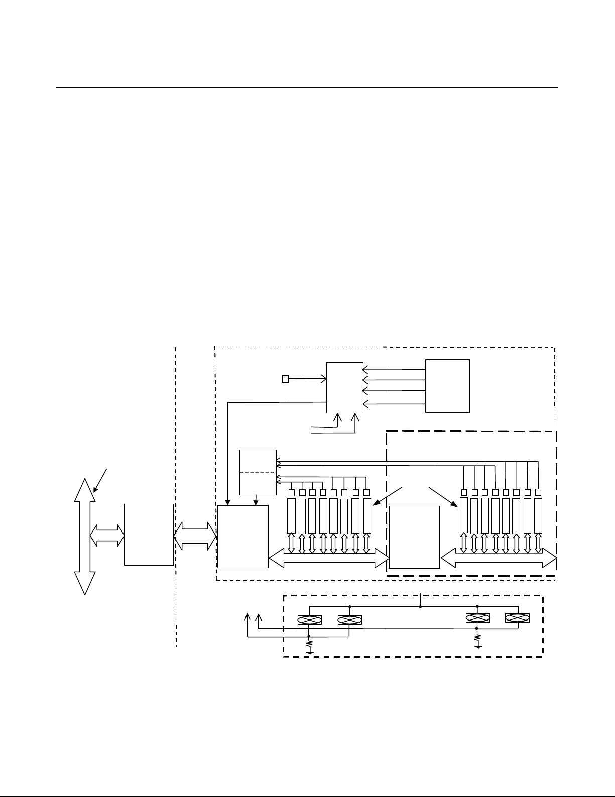
Figure 1-1 shows the functional relationships of both model versions and special features of the unit.
Host Primary Bu s
Host
PCI
Bridge
Compact PC
Cable
Backplane
Temperature
Sensor
Fan Voltages
A/D 1
A/D 2
Chassis
PCI
Bridge
Fan Voltages
to A/D
A/D 0
Optional
Slot Temperature Sensors
141315
12
11
10
89
Chassis Secondary Bus
OPTIONAL FAN HOUSING
3.3VDC
5VDC
12VDC
−12VDC
Voltage Monitors
STLITE-CPCI-16R+
CPCI
Card
Slots
Chassis
PCI
Bridge
12VDC
Only
STLITE-CPCI-8R
ATX
Power
Supply
Slot Temperature Sensors
0
2
1
Chassis Secondary Bus
Optional
3
54
6
7
STLITE CPCI-8R/16R Compact PCI Expansion System
Figure 1-1. Functional Block Diagram- STLITE-CPCI-8R/16R Expansion Chassis
1
Page 6
2. COMPONENTS – STANDARD SYSTEM
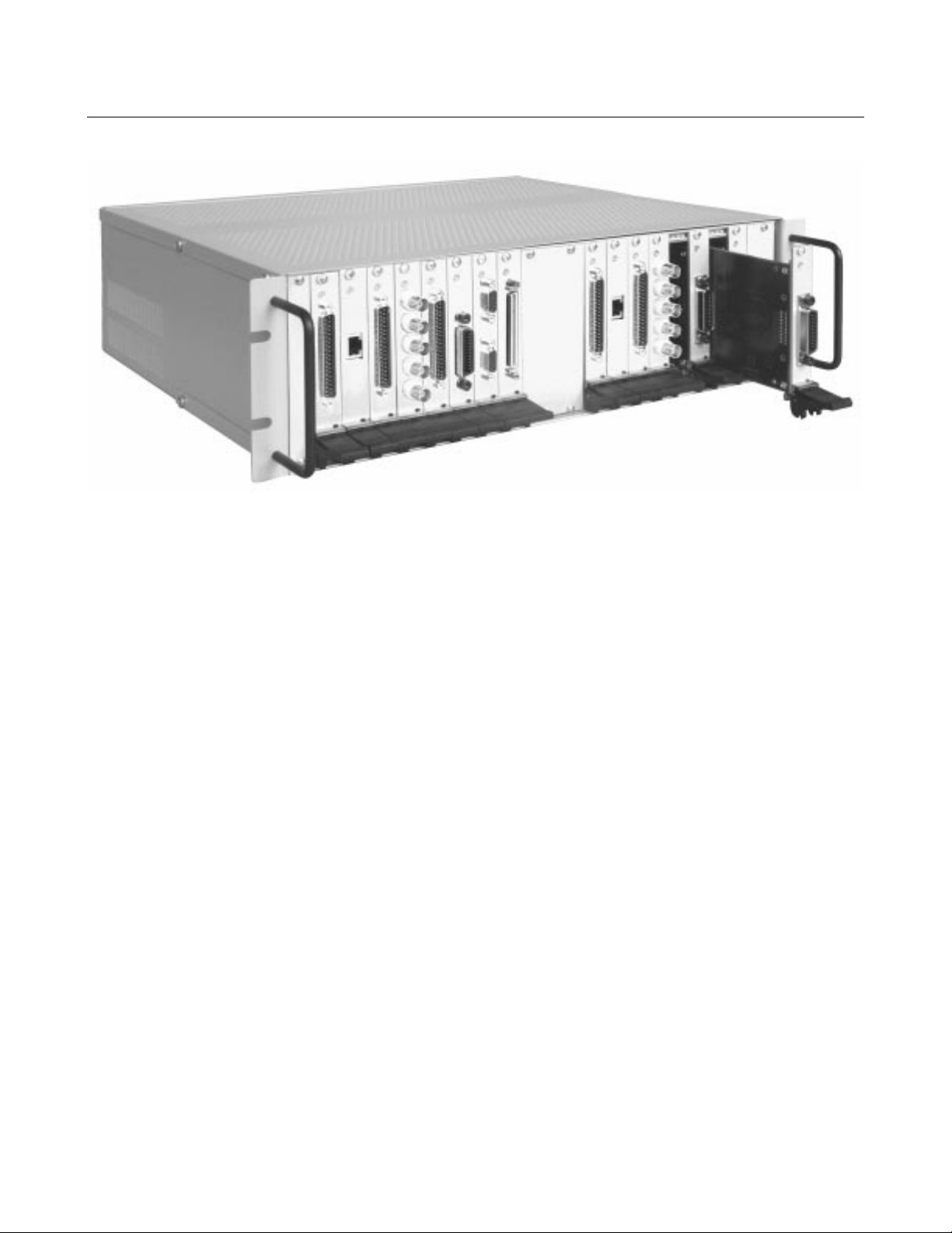
The STLITE-CPCI-16R (Figure 2-1) consists of the following major components:
Figure 2-1. STLITE-CPCI-16R
2.1 CPCI EXPANSION MOTHERBOARD
The expansion motherboard is a printed circuit board mounted vertically in the back of the rack enclosure. It
receives bus signals from the host computer and places equivalent signals on the chassis secondary buses. There
are either eight or sixteen slots on the secondary bus for installing boards. Each group of eight slots is serviced
by an Intel 21150-AC, 32-bit, 33 MHz bridge chip.
A semiconductor sensor is provided on the expansion motherboard for temperature monitoring. Its output is
applied to an A/D converter along with power supply voltages (±12V, +5V, and +3V). If the optional fan tray is
used, two voltage signals from two pairs of DC-powered cooling fan are applied to the A/D for conversion.
Optionally, each of the eight (or sixteen) card slot locations has a semiconductor temperature sensor mounted
over it. The sensors are mounted on a PCB strip mounted on the top of the chassis. Signals from these sensors
are converted to digital values by a second A/D. The digital values, along with other monitor data, are sent to the
host computer over the expansion cable.
2.2 HOST BRIDGE CARD: STLITE-PCI-HOST; STLITE-CPCI-HOST
The Host Bridge card is a PCI or CPCI adapter card that can be installed in any open slot in the host computer.
The Host Bridge card is connected via a three-foot shielded ribbon cable to an expansion bridge card in the back
of the STLITE-CPCI-8R/16R Expansion Chassis.
2.3 POWER SUPPLY
The STLITE-CPCI-8R/16R incorporates a standard 250-Watt, ATX-type switching power supply in the cabinet.
A cooling fan is integrated in the power supply. All four output voltages are monitored to an accuracy of ±2%.
The power supply operates on either 115 or 230VAC (switch-selected).
2
Page 7

2.4 EXPANSION CABLE
The STLITE-CPCI-8R/16R is supplied with a STLITE-C-3 cable. This is a shielded three-foot cable for
connecting the host bridge card to the expansion chassis bridge. The connectors are 80-pin, D-type. Longer
cable lengths are neither advisable nor available.
2.5 CABINET
The STLITE-CPCI-8R/16R chassis is totally enclosed in a heavy-gauge aluminum rack-mounted enclosure. To
access a card slot, remove the filler plate for that slot by backing out the two captive screws.
A standard AC jack is mounted on the rear panel next to the AC power ON/OFF switch. An AC voltage-select
switch is provided to select power supply operating voltage (115 or 230VAC).
3. INSTALLATION & START-UP – STANDARD SYSTEM
3.1 PRELIMINARY INSTRUCTION
CAUTION
All CPCI cards are susceptible to damage from electrostatic discharges. When carrying cards,
always keep them in their anti-static packaging. When setting a bare card down, place it on an
anti-static surface. We strongly recommend using a grounded wrist strap and/or working on a
grounded floor pad.
3.2 HOST BRIDGE CARD INSTALLATION
There may be a bank of several switches on the host card (S1). These switches should be left as set at the
factory (all switches to the right – toward the edge of the card).
1. Remove power from your host computer system.
NOTE: Do NOT disconnect the power cable. Doing so removes the ground connection.
2. Remove the computer’s cover. Refer to the system owners manual if necessary.
3. Insert the Host PCI/CPCI Bridge card in any available card slot. Secure the card.
4. Install slot covers on any open backplane locations.
5. Replace the computer cover. DO NOT APPLY POWER YET.
3.3 CARD INSTALLATION - EXPANSION CHASSIS
With no power applied to either the host computer or the CPCI Expansion chassis, remove the aluminum filler
plate(s) for the desired slot(s). We recommend configuring all unused slots with filler plates.
3
Page 8

3.4 CPCI EXPANSION CABLE INSTALLATION
1. Position the chassis within easy reach of the three-foot cable.
2. Attach the cable to the Host Bridge card. Secure it firmly by tightening both captive thumbscrews on the
connector.
3. Attach the cable to the Chassis CPCI Bridge card located on the rear of the chassis. Secure it firmly by
tightening both captive thumbscrews on the connector.
CAUTION
The CPCI expansion cable is a specially fabricated cable having a sheath of shielding around the wire ribbon. It
is somewhat stiff and can be damaged if handled roughly. Use care when installing it.
Avoid making any sharp bends or pinches.
3.5 CPCI CARD INSTALLATION
1. POWER-DOWN. Make sure that no AC power is applied to the expansion chassis or host computer.
2. PROTECT AGAINST ELECTROSTATIC DISCHARGE. Before handling CPCI boards, put a grounding
wrist strap on. If a grounding floor mat is available, use it.
3. CPCI card addresses are set up by BIOS software. Typically, it makes no difference which slot is used,
unless specified by the card manufacturer. Carefully press the card fully into the slot connector, secure the
latch, and install the securing screw in the backplane bracket.
NOTE: Not all CPCI cards may work universally in any slot. If a problem is experienced, try using a
different slot or re-order the existing card sequence.
The large number of CPCI cards and device drivers available make it impossible to fully test and certify
every card from every manufacturer for use in the STLITE-CPCI-8R/16R. To avoid possible problems,
always require that the CPCI card vendor provides certification that the cards comply with PICMG 2.0 R2.1.
Compliance of your entire systems to this specification is highly recommended and will be your best
assurance of a trouble-free system.
3.6 CABLE INSTALLATION
1. Use great care when connecting and routing cables to avoid damaging the conductors (this is especially
important for ribbon cables). Strive to keep cables as short as possible, but leave enough slack (or “service
loops”) easy installation and removal.
2. Avoid running signal cables and power cables next to each other.
3. If noise pick-up is a problem, re-locate the cable runs or use shielded cables.
3.7 FINAL INSTALLATION CHECK
1. Check the installation before powering up for the first time. The power supply has an over-voltage
protection circuit. However, it may not trip in time to protect a device that has been improperly hooked up
or whose power cable has been damaged.
2. Check that the AC Voltage select switch on the rear panel of the CPCI-Expansion Chassis is set for the
correct voltage (either 115 or 230VAC).
3. Attach the AC power cable to the CPCI-Expansion Chassis.
4
Page 9

4. POWERING-UP
4.1 SEQUENCE FOR APPLYING POWER
It is important that higher-numbered PCI buses in your system’s hierarchy be powered-up and in a stable state at
the time the host computer comes up and issues a master power-on bus reset. In systems that perform automatic
PCI bus configuration, this allows the configuration software to recognize the PCI bus hierarchy and all attached
devices.
NOTE: It is desirable for the host computer and the CPCI Expansion Chassis to receive their AC power
from the same, protected, local AC power source.
1.
POWER-ON –
2. Apply power to the host system.
NOTE: If you have multiple (daisy-chained) CPCI Expansion Chassis, apply power to the most
“downstream” unit first, then the next ‘upstream” unit, etc., and finally, power-up the host computer.
Place the AC power switch on the rear panel of the CPCI Expansion Chassis ON (I)
4.2 POWERING DOWN
There is no requirement for sequential powering-down of the system. You can shut down system units in any
order you wish.
5. MULTIPLE CHASSIS INSTALLATION
5.1 INTRODUCTION
The PCI Local Bus Specification defines the PCI bus as a hierarchical bus where PCI-to-PCI Bridges (PPBs)
can be used to add “levels” to the PCI bus hierarchy.
Thus, you can add two or more STLITE-CPCI-8R/16R chassis to your system configuration. It can be done in
either a “daisy-chain” (serial) manner or a fan-out (serial/parallel) fashion. Each configuration has its own
advantages and applications.
In a daisy chain configuration (Figure 5-1), expansion chassis are added serially at the end of the PCI bus
hierarchy, one PPB after another. This adds “depth” to the local PCI bus by increasing the number of active
local bus levels in the system configuration.
Each PCI bridge has a primary side and a secondary side. Take, for example, the addition of a bridge to existing
PCI Bus 0. The new bridge is attached to the secondary side of the first bridge and the new bridges secondary
side becomes Local Bus 1. The primary side is defined as the side attached to the lower numbered, or upstream
PCI Local Bus. A bridge attached to the secondary side of the new bridge (Bus 1) would be assigned a higher
number (Bus 2) and considered downstream of Bus 1.
5.2 DAISY-CHAIN CONFIGURATION
The PCI bus in your host computer is typically numbered “0”. Each new PPB adds a new bus level into the
hierarchy. The Host Bridge card, when plugged into the host computer, has as its primary side, Bus 0. Its
downstream side (the cable) is Bus 1 (Figure 5-1).
The first expansion chassis also has one or two PPBs (for an eight- or 16-slot rack). The first PPB has its
primary side connected to Bus 1 (the cable) and its downstream feeds Bus 2 on the chassis motherboard.
In a 16-slot rack (STLITE-CPCI-16R), the second PPB has Bus 2 as its primary side and Bus 3 is the secondary.
If you were to insert another Host CPCI Bridge card in an open slot in first expansion rack, its primary side
would be attached to Bus 2 or Bus 3 depending on the slot chosen (Figure 5-1). Its cable (secondary side) will be
5
Page 10

either Bus 3 or 4. Thus, the first PPB in the second expansion rack will have its primary attached to Bus 3 or 4
(
)
its secondary will be motherboard’s Bus 4 or 5. A 16-slot rack will have its second bus as number 5 or 6.
Bus 0
Host
PCI/CPCI
Host
Bridge
Bus 1
Bus 1
(Cable)
Computer
Daisy-Chained, 2nd
PCI Bridge
Bus 2
(Board)
8 slots
PCI Bridge
(16-slot rack)
Bus 3
(Board)
8 slots
First
Bus 2
Attachment to STLITE-CPCI-8R, or
Alternate for STLITE-CPCI-16R
Second
Host PCI
Bridge
2nd Rack
Alternate Attachment to Bus 3
(for STLITE-CPCI-16R only)
STLITE-CPCI-8R/16R
Bus 3 or 4*
Cable
STLITE-CPCI-8R/16R
*If the 2nd Host CPCI bridge is connected to Bus
2 (in either an 8- or 16-slot rack), its cable will be
Bus 3. But, if connected to the second bus (#3)
in a 16- slot rack, its cable will be Bus 4.
Board bus number(s) will vary accordingly.
First
PCI Bridge
Bus 4 (or 5)
(Board)
Second
PCI Bridge
(16-slot rack)
8 slots
Bus 5 (or 6)
(Board)
8 slots
Daisy-Chained STLITE-CPCI-8R/16R Expansion Racks
Figure 5-1. CPCI Expansion Daisy Chaining
6
Page 11

5.3 FAN-OUT CONFIGURATION
In this configuration, the Host Bridge card for a second CPCI chassis is inserted in an open slot in the first
expansion rack. The Host Bridge card for the first rack is inserted in an open slot of the host computer as usual.
The first and second expansion racks have bus level numbers identical with the daisy chain configuration
described above.
Adding a third expansion chassis (PPB) to Bus 2 is the fan-out (parallel) configuration (Figure 5-2).
NOTE: Although we have numbered the second chassis to extend from Bus 2 as “Bus 6”, logically, it is at the
same hierarchical level as Bus 4 since it is attached to Bus 2.
HOST
Bus 0
PCI/CPCI
Host
Bridge
Bus 1
(Cable)
First Rack
PCI Bridge
Bus 2
Bus 2
(8 slots)
Bus 2
STLITE-CPCI-8R/16R
COMPUTER
Second Rack
PCI Host
Bridge
Third Rack
CPCI Host
Bridge
STLITE-CPCI-8R/16R
Bus 3
(Cable)
Second Rack
PCI Bridge
Bus 5
(Cable)
Third Rack
PCI Bridge
STLITE-CPCI-8R/16R
Bus 4
(8 slots)
Bus 6
(8 slots)
Fan-Out Configuration – Satellite CPCI Expansion System
Figure 5-2. CPCI-Expansion-Serial/Parallel Configuration for Rack-Mounted Units
7
Page 12

5.4 EXTENDED DAISY CHAIN CONFIGURATION
If, rather than attaching the third expansion chassis to Bus 2, we had attached it to Bus 6 (in the second
expansion rack), then the first motherboard bus in the 3
than Bus 4. (Actually, if attaching to Bus 6 in the 2
rd
rack would be further downstream (logically speaking)
nd
rack, the first bus in the 3rd will be Bus 8.)
All of this not withstanding, bus numbering is determined by the algorithm implemented by your BIOS or
console firmware configuration code. The labeling shown in the prior examples assumes:
1. The BIOS or firmware runs a true “depth-first” search on the PCI bus hierarchy.
2. Your BIOS or firmware will actually deal with multiple PPBs.
5.5 CPCI CARD CONFLICTS
If it appears that a CPCI card is interfering with the operation of another, try reorganizing the card layout on the
motherboard. Sometimes, changing the order that the BIOS or firmware configures the cards will resolve
conflict issues.
5.6 BIOS/FIRMWARE REQUIREMENTS
System manufacturers use various names for their console firmware. For example, IBM-PC-compatible
firmware is called BIOS code. SUN or MAC computers call it “Open Firmware” code. DEC Alpha computers
running UNIX have “SRM Console Code” but on Digital computers running Windows NT, its referred to as
“ARC Console Code” or “Alpha BIOS.
Naming conventions aside, the firmware performs the same functions. It must contain a set of hardware-specific
routines that are called during the early phases of a start-up. These callable routines recognize the PCI hardware
and configure the system architecture for use.
The PCI BIOS specification is the part of the PCI Local Bus Specification that deals with this class of code. A
similar standard for non-WinTel systems is IEEE 1275-1994 Open Firmware Bus Binding Specification. These
standards provide a consistent architecture for PCI option identification and configuration during a system bootup.
During boot-up, the CPCI bus is probed to determine what cards are present. The probe instructions determine
which slots contain valid cards and which are unused. The configuration code should be able to look at up to
255 PCI/CPCI buses, detect all installed cards, and perform all configuration processing for each PCI/CPCI
card.
In order to configure all installed CPCI cards in an expanded system, the console firmware must be able to
traverse multiple levels of bridges. While 255 is the theoretical limit, the actual limit is lower but still should be
100 or more.
Typically the firmware or BIOS code accommodates multiple bridges (and PCI buses). However, some older
systems place a limit on the number of bridges that can be configured during a start-up. Your firmware must be
able to address at least two levels of PCI-to PCI bridges in order to use an 8-slot CPCI Expansion Chassis. A 16slot CPCI expansion system would require four bridge levels.
For daisy-chained or fanned-out systems, count all the bridge levels to the most deeply nested PCI bus to
determine the number of bridge levels that must be traversed.
If you are experiencing problems with installation and detection of multiple bridges or multiple PCI boards,
refer to the Satellite Systems link on the Measurement Computing website (www.measurementcomputing.com).
8
Page 13

6. SATELLITE MONITOR SOFTWARE INSTALLATION AND USE
Included with the Satellite expansion chassis is the Satellite Parametric Monitor Application for monitoring
supply voltages, slot and cavity temperatures, and fan current. In addition, the Satellite Series Monitor Library is
provided for programming your own applications for accessing the extra features provided by the Satellite
devices. For more information regarding the library and its usage, please refer to the README.TXT file on the
installation CD.
6.1 INSTALLATION
The Satellite Monitor Software can be installed on all 32-bit Windows platforms (Win 95/98/ME and
Win NT/2000) using the Satellite Utility CD or diskettes. Simply insert the Satellite Utility CD or diskette into
the appropriate drive, run the program SETUP.EXE in the root directory, and follow the installation instructions
provided. Note that on some systems, the CD installation will start automatically.
6.2 USING THE
To run the Satellite Monitor application, please select on the “Satellite Monitor” item located under Program
Files Æ Measurement Computing of the Start menu. On opening, this application automatically locates all
available Satellite devices connected to the host computer and creates a window for each Satellite. Each window
will display all available sensor measurements in a grid. It provides one of three views in a strip chart displaying
up to the latest 24-hour history of the Temperature, Supply Voltage, or Fan Current measurements (Figure 6-1).
SATELLITE
MONITOR PROGRAM
Figure 6-1. Strip Chart Temperature Display
9
Page 14

Each Satellite device is identified by its model name and
secondary bus number included in the title bar of each
window (Figure 6-2),
To view or activate each Satellite window, click on
the Window menu and select the desired Satellite.
Additional windows attached to each Satellite can be
created through the New Window item under the
Window menu (Figure 6-3).
To change the data viewed in the strip chart, simply
select Temperature, Supply Voltages, or Fan Current
menu items under View (Figure 6-4).
Figure 6-2. Title Bar Device Name
Figure 6-3. Window Menu
To customize the vertical scale of the strip charts, open the
Scale Axes...dialog by selecting the Scale Axes item under the
Format menu (Figure 6-5, 6-6).
Figure 6-4. View Menu
Figure 6-5. Format MenuView Menu
10
Figure 6-6. Format Menu > Scale Axes
Page 15

To add or remove traces from the strip charts, select the Data Sources item under the Format menu, and select or
f
deselect the checkboxes corresponding to the desired traces.
6.3 WATCH DOG TIMER AND ALARM
To enable or disable the watchdog timer, select
Watchdog… under the Control menu (Figure 6-7).
Set the Watchdog Timeout Period to match that o
the hardware settings. Click the button labeled
“Enable Satellite Watchdog Timer” to enable the
watchdog (Figure 6-8).
After being enabled, the button will read “Disable
Satellite Watchdog Timer.” Clicking on the button
labeled “Disable Satellite Watchdog Timer” will
disable the watchdog timer and set the button label
to read "Enable Satellite Watchdog Timer.”
Note that the watchdog timer may alarm even under
proper operation if the timeout period entered in the
dialog is more than twice its hardware settings.
The Expansion card located in the rear of the STLITE chassis offers some useful features for event monitoring
and control. All access to the watchdog timer and alarm features is via the P3 header located on the top-right
portion of the Expansion card. In operation, the watchdog timer will repeatedly assert a timeout signal at the end
of the selected period. When enabled, this timeout signal is used to assert the Alarm_Out and Alarm_Out/n
signals. In addition, the Alarm_Out signal provides control of an undedicated SPDT relay. In the Alarm state
(timer expired) the relay closes, otherwise it is in the open position.
It is necessary to remove the top cover of the unit to access these features. Using a Torx T-10 driver, loosen the
four retaining screws and lift off the cover.
Do not remove the screws
Figure 6-8. Watchdog Timer Settings Display
Figure 6-7. Control Menu
.
A diagram and pinout of the P3 header is shown below in Figure 6-9.
Pin 2
Pin 1
Figure 6-9. P3 Header
11
Page 16

The watchdog timer period is set via a jumper. The default position of 30 seconds is shown above. Table 6-1
below describes the W/D timer settings as well as the other header pins.
Table 6-1. Watch Dog Timer Settings
Pin Description
1 30 S timeout when jumpered to Pin2
2 See above
3 10 second timeout when jumpered to Pin 4
4 See above
5 1 second timeout when jumpered to pin 6
6 See above
7 Alarm_Out/n (TTL)
8PC +5V
9 Alarm_Out (open collector up to +12V)
10 Alarm _Out 5K pullup TO 5V when jumpered to
pin 9
11 SPDT Relay Common
12 SPDT Relay Normally Open
13 No Connection
14 SPDT Relay Normally Closed
15 No Connection
16 No Connection
6.4 EXAMPLE PROGRAMS
Example programs written in C/C++, Visual Basic (v5.0 and later), and Delphi (v3.0 and later) are included with
the Satellite Monitor. They demonstrate how to use each of the API functions provided by the Satellite Library.
These examples are installed in the subdirectories C, VB, and Delphi of the installation directory.
12
Page 17

7. REGISTER MAP
REGISTER MAP
7.1
The STLITE -CPCI-8R/16R provides two sets of general-purpose I/O bits (GPIO0-GPIO3). The first set of
GPIO control bits is provided by the PCI Host card’s 21150 PCI-PCI bridge chip. The second set is provided by
the Expansion board’s 21150 PCI-PCI bridge chip.
The PCI Host card GPIO control bits provide direct control over the user-configurable watchdog timer circuit.
The Expansion card GPIO bits interface bits interface directly to the serial control bits used to configure and
control the voltage, temperature and current measuring A/D converters.
7.2 EXPANSION BOARD 21150 BRIDGE REGISTERS
GPIO OUT Register
D7 D6 D5 D4 D3 D2 D1 D0
OE/ALARM_OFF X S_CLK SDI OE/ALARM_ON X S_CLK SDI
GPIO3 GPIO2 GPIO1 GPIO0 GPIO3 GPIO2 GPIO1 GPIO0
( 0x65 offset of PCI Header ) Read/Write
This register provides access to the serial data I/O control bits. The Expansion board provides these bits for the
user to control the precision A/D converters, which measure the various chassis temperatures, voltages and fan
currents.
This register also provides direct control over the ALARM output bit and the ALARM relay output bits
described in Section 6.2. Configuring the ALARM function requires that the WD configuration bit (bits 1 or 5)
in the HOST 21150 GPIO OUT register (0x65) be configured in conjunction with bits 3 or 7 of this register.
To address specific A/D converters, use the GPIO control bits and the following chip select lookup table. See
the TI TLV2548 datasheet for more specific information concerning the configuration of the A/D converters.
SDI S_CLK A/D Function
L L A/D_0 Measures voltages, cavity temperature and fan current
H L A/D_1 Measures temperature of CPCI slots 0-7 ( –16R+ Only)
L H A/D_2 Measures temperature of CPCI slots 8-15 (-8R+ and –16R+)
The order of operations for programming the A/D converters should include:
1. Selecting the specific A/D converter chip (see chip select table above).
2. Configuring the A/D converter (see TI TLV2548 datasheet for specifics).
Note: The Expansion board hardware provides each of the A/D converters with an external, precision
reference. Attempting to re-configure the A/D converters to use an internal reference will produce
inaccurate results.
3. Read/Write data to and or from the A/D converter.
Bits 0-3 of this register operate in a “Write-1-To-Clear” manner. Writing a “1” to any bit in the lower nibble
will drive the corresponding GPIO bit low even if it has been previously programmed as bi-directional. Bits
previously programmed as input-only are not driven.
Bits 4-7 of this register operate as “Write-1-To-Set.” Writing a “1” to any bit in the upper nibble will drive the
corresponding GPIO bit high even if it has been previously programmed as bi-directional. Bits previously
programmed as input only are not driven.
Writing a “0” to this register has no effect, while reading from this register returns the last value poked in.
13
Page 18

GPIO IN Register (0x67 offset of PCI Header) Read Only
D7 D6 D5 D4 D3 D2 D1 D0
X SDO X X RESERVED RESERVED RESERVED RESERVED
GPIO3 GPIO2 GPIO1 GPIO0
This register provides read-back capability for the serial data (SDO) from any one of the three A/D converters
used to measure slot temperature, power supply voltages or fan current.
The lower nibble (bits 0-3) is reserved by the 21150 bridge chip. Reading from this part of the register will
return all zeros.
NOTE: When reading the upper nibble (bits 4-7), be sure to mask off unwanted bits to avoid incorrect data
being returned.
GPIO CNTRL Register (0x66 offset of PCI Header) Read/Write
D7 D6 D5 D4 D3 D2 D1 D0
GPIO3_BI GPIO2_BI GPIO1_BI GPIO0_BI GPIO3_IN GPIO2_IN GPIO1_IN GPIO0_IN
This register configures each of the Expansion card’s GPIO bits as either bi-directional or input type.
Bits 0-3 of this register operate in a “Write-1-To-Clear” manner. Writing a “1” to any bit in the lower nibble
will configure the correspond ing GPI O bit as input type.
Bits 4-7 of this register operate as “Write-1-To-Set.” Writing a “1” to any bit in the upper nibble will configure
the corresponding GPIO bit as bi-directional.
Writing the value “0” to this register has no effect. Reading from this register returns the last value poked in.
7.3 SATELLITE HOST BOARD 21150 BRIDGE REGISTERS
GPIO OUT Register ( 0x65 offset of PCI Header ) Read/Write
76543210
XXWD_ONXXXWD_OFFX
GPIO3 GPIO2 GPIO1 GPIO0 GPIO3 GPIO2 GPIO1 GPIO0
This register is used to control the user-configurable watchdog timer circuit located on the Expansion board.
Writing a “1” to the WD_OFF bit of the lower nibble will disable the Watchdog Timer.
Writing a “1” to the WD_ON bit in the upper nibble will turn the Watchdog Timer on.
Writing the value “0” to this register has no effect, while reading from this register will return the last value
poked in.
GPIO CNTRL Register (0x66 offset of PCI Header) Read/Write
D7 D6 D5 D4 D3 D2 D1 D0
GPIO3_BI GPIO2_BI GPIO1_BI GPIO0_BI
This register configures each of the PCI Host card GPIO bits as either bi-directional or input type.
Bits 0-3 of this register operate in a “Write-1-To-Clear” manner. Writing a “1” to any bit in the lower nibble
will configure the correspond ing GPI O bit as input type.
GPIO3_IN GPIO2_IN GPIO1_IN GPIO0_IN
Bits 4-7 of this register operate as “Write-1-To-Set.” Writing a “1” to any bit in the upper nibble will configure
the corresponding GPIO bit as bi-directional.
Writing the value “0” to this register has no effect. Reading from this register returns the last value poked in.
14
Page 19

STLITE-PCI-HOST, STLITE-CPCI-HOST
8. SPEC IFICATIONS
Typical for 25°C unless otherwise specified
.
Power consumption
+5V 375 mA max
Features
Bridge Industry standard bridge. Intel 21150-AC. PCI 2.1, 32-bit 33 MHz PCI.
Provides support for delayed transactions, enabling memory read, I/O, and
configuration read buffering.
Connector Shielded 80-pin SCSI D-type. Interfaces with Measurement Computing’s
Satellite Series bus expansion products.
Required Cable STLITE-C-3. Three-foot shielded ribbon, 80-pin, D-type
Interrupts
Interrupts INTA#, INTB#, INTC#, INTD# routed to host PC
Environmental
Operating Temperature Range 0 to 70°C
Storage Temperature Range
Humidity 0 to 95% non-condensing
−40 to 100°C
Mechanical
Card Dimensions STLITE-PCI-HOST: Universal PCI variable-length Short Card:
137.0mm L x 18.0mm W x 107.0mm H
STLITE-CPCI-HOST: +5V 3U CPCI:
160.0mm L, 100.0mm W, 20.3mm H
15
Page 20

HOST BRIDGE CONNECTOR PIN OUT
Pin Signal Name Pin Signal Name
1 GND 41 HST_S_AD00
2 HST_5V 42 HST_S_AD01
3 GND 43 HST_S_AD02
4 PWR_MON 44 HST_S_AD03
5 GND 45 HST_S_AD04
6 HST_S_SERR# 46 HST_S_AD05
7 GND 47 HST_S_AD06
8 HST_S_LOCK# 48 HST_S_AD07
9 GND 49 HST_S_CBE0#
10 HST_S_STOP# 50 HST_S_AD08
11 GND 51 HST_S_AD09
12 HST_S_DEVSEL# 52 HST_S_AD10
13 GND 53 HST_S_AD11
14 HST_S_TRDY# 54 HST_S_AD12
15 GND 55 HST_S_AD13
16 HST_S_ FRAME# 56 HST_S_AD14
17 GND 57 HST_S_AD15
18 HST_S_IRDY# 58 HST_S_CBE1#
19 GND 59 HST_S_PAR
20 HST_S_PERR# 60 HST_S_CBE2#
21 GND 61 HST_S_AD16
22 HST_S_GNT# 62 HST_S_AD17
23 GND 63 HST_S_AD18
24 HST_S_REQ# 64 HST_S_AD19
25 GND 65 HST_S_AD20
26 HST_S_RST# 66 HST_S_AD21
27 GND 67 HST_S_AD22
28 HST_GPIO3 68 HST_S_AD23
29 HST_GPIO2 69 HST_S_CBE3#
30 HST_GPIO1 70 HST_S_AD24
31 HST_GPIO0 71 HST_S_AD25
32 INTB#_EXP 72 HST_S_AD26
33 GND 73 HST_S_AD27
34 INTC#_EXP 74 HST_S_AD28
35 GND 75 HST_S_AD29
36 INTA#_EXP 76 HST_S_AD30
37 GND 77 HST_S_AD31
38 INTD#_EXP 78 GND
39 GND 79 S_CLK+
40 S_CLK- 80 GND
16
Page 21

STLITE-CPCI-16R, STLITE-CPCI-16R+, STLITE-CPCI-8R, , STLITE-CPCI-8R+
Typical for 25°C unless otherwise specified.
Features
Slots STLITE-CPCI-16Rx: Sixteen 3U CPCI slots
STLITE-CPCI-8Rx: Eight 3U CPCI slots
PCI Bus Embedded industry standard bridge, Intel 21150-AC
32 bit, 33 MHz.
Power Supply 250W ATX Style
Line Voltage Input 115VAC/10A or 230VAC/5A, switch-selectable, 50/60Hz
Power Ratings
Volts Minimum
Load
+3.3V
2
0.2 Amps 14 Amps ±10% 46W
+5V 2.0 Amps
3,4
+12V
0.2 Amps 9 Amps ±5% 108W
5
Maximum
Tolerance Power
Load
27 Amps ±5% 135W
1
−12V
0.0 Amps 0.5 Amps ±10% 6W
(1) Total Power not to exceed 250W
(2) Backplane circuits consume 730 mA from the +3.3V supply.
(3) The system monitoring hardware consume 40 mA from the +12V supply.
(4) The optional fan tray with 4 fans consumes 500 mA (typical) from the +12V
supply.
(5) For some ATX power supplies, if the minimum load is not drawn from the +5V
supply, the −12V supply may be out of tolerance.
Certification UL
CE
CSA
FCC Class A Approved
Interface Connector Shielded 80-pin SCSI D-type. Interfaces with Measurement Computing Satellite
Series bus expansion products.
Interface Cable STLITE-C-3. Three-foot shielded ribbon, 80-pin, D-type.
17
Page 22

System Monitoring
System monitoring features are accessed via VB/C++ example programs and DLL provided with the product.
A/D Converter TLV2548, 8-channel, 12-bits.
One per STLITE-CPCI-16R/-8R
Three per STLITE-CPCI-16R+.
Two Per STLITE-CPCI-8R+
CPCI voltages; +5V, +3.3V, +12V, and –12V
Absolute Accuracy: ±2%
Sensor
Backplane One sensor located in the back cavity
Slots (only available on STLITE-CPCI-
16R+/8R+)
Current Monitoring 15 mA < I < 450 mA, 6% absolute accuracy. Independent for left
Fan Tray Connector Each chassis includes a fan tray cable with Positronics
Timeout Jumper-selectable for 1, 10, and 30 seconds
Alarm Alarm outputs provide TTL, 500 mA current sink and
Semiconductor type, Range: −55 to 150°C,
Resolution: 0.03°C
Absolute Accuracy: ±2.5°C max, ±0.9°C typ over entire range.
One sensor positioned above each slot on a circuit card mounted
inside the chassis
and right-side fan pairs. Each fan pair protected with 500 mA
resetable fuse. Fan currents of 15 mA or less indicate an OFF or
OPEN condition.
PLA03F0000 connector. Mates with Measurement Computing’s
optional STLITE-CPCI-FAN unit.
SPDT relay NO/NC/C pins.
Environmental
Operating Temperature Range 0 to 50°C
Storage Temperature Range
Operating Humidity 0 to 90% non-condensing
Storage Humidity 0 to 95% non-condensing
−20 to 65°C
Mechanical
Enclosure 19” Rack Mount design
Dimensions 14.30" L x 17.16" W x 5.24" H
Weight 11 lbs.
Construction 0.030" and 0.080" Aluminum
Cooling Power supply fan plus an optional fan tray with four fans
18
Page 23

CHASSIS BRIDGE CONNECTOR PIN OUT
Pin Signal Name Pin Signal Name
1 GND 41 HST_AD00
2 PWR_MON 42 HST_AD01
3 GND 43 HST_AD02
4 TRGT_5V 44 HST_AD03
5 GND 45 HST_AD04
6 HST_SERR# 46 HST_AD05
7 GND 47 HST_AD06
8 HST_LOCK# 48 HST_AD07
9 GND 49 HST_CBE0#
10 HST_STOP# 50 HST_AD08
11 GND 51 HST_AD09
12 HST_DEVSEL# 52 HST_AD10
13 GND 53 HST_AD11
14 HST_TRDY# 54 HST_AD12
15 GND 55 HST_AD13
16 HST_FRAME# 56 HST_AD14
17 GND 57 HST_AD15
18 HST_IRDY# 58 HST_CBE1#
19 GND 59 HST _PAR
20 HST_PERR# 60 HST_CBE2#
21 GND 61 HST_AD16
22 HST_GNT# 62 HST_AD17
23 GND 63 HST_AD18
24 HST_REQ# 64 HST_AD19
25 GND 65 HST_AD20
26 HST_RST# 66 HST_AD21
27 GND 67 HST_AD22
28 HST_GPIO3 68 HST_AD23
29 HST_GPIO2 69 HST_CBE3#
30 HST_GPIO1 70 HST_AD24
31 HST_GPIO0 71 HST_AD25
32 INTB#_EXP 72 HST _AD26
33 GND 73 HST_AD27
34 INTC#_EXP 74 HST_AD28
35 GND 75 HST_AD29
36 INTA#_EXP 76 HST _AD30
37 GND 77 HST_AD31
38 INTD#_EXP 7 8 GND
39 GND 79 HST _ CLK+
40 HST_CLK- 80 GND
19
Page 24

For Your Notes
20
Page 25

EC Declaration of Conformity
We, Measurement Computing Corp., declare under sole responsibility that the product:
STLITE-CPCI-8R
STLITE-CPCI-16R
CPCI BUS EXPANSION CHASSIS
CPCI BUS EXPANSION CHASSIS
Part Number Description
to which this declaration relates, meets the essential requirements, is in conformity with, and CE
marking has been applied according to the relevant EC Directives listed below using the relevant
section of the following EC standards and other normative documents:
EU EMC Directive 89/336/EEC: Essential requirements relating to electromagnetic compatibility.
EU 55022 Class B: Limits and methods of measurements of radio interference characteristics of
information technology equipment.
EN 50082-1: EC generic immunity requirements.
IEC 801-2: Electrostatic discharge requirements for industrial process measurement and control
equipment.
IEC 801-3: Radiated electromagnetic field requirements for industrial process measurements and
control equipment.
IEC 801-4: Electrically fast transients for industrial process measurement and control equipment.
Carl Haapaoja, Director of Quality Assurance
Page 26

Measurement Computing Corporation
16 Commerce Boulevard,
Middleboro, MA 02346
(508) 946-5100
Fax: (508) 946-9500
E-mail: info@measurementcomputing.com
www. measurementcomputing.com
 Loading...