

Page 1
RS-232 to USB Interface Adapter Kit Quick Start
Before you get started
Verify that you have the following items.
Data Acquisition Device
RS-232 to USB Interface Adapter Kit
Monitor: SVGA, 1024 x 768 screen resolution
Windows 2000 SP4 and Windows XP users:
PC with Intel™ Pentium [or equivalent]; 1GHz
512 MB memory; 10 GB disk space
Windows Vista users:
PC must be Windows Vista Premium Ready
Step 1 - Install Software (Software must be installed before connecting hardware)
1. Close all running applications on the host PC.
2. Insert the Data Acquisition CD (8.1.2 or higher) into your CD-ROM drive and wait for the PC to auto-run. An Opening
Screen will appear. If AutoRun is disabled: (a) right click Windows Start menu, (b) select Explore; and (c) double-click
MasterSetup.exe. As an alternative to using the CD, you can download software from: www.iotech.com/ftp.html
3. Click the <ENTER SETUP> button.
Note: If you are downloading software from our website, follow instructions provided there.
4. From the hardware selection screen, select your data acquisition device then follow the on-screen instructions.
Note - ChartView Users:
ChartView is used with ChatScan/1400, TempScan/1100, and MultiScan/1200.
To enable all ChartView features:
(a) From ChartView’s main window, open the File pull-down menu,
(b) select Authorization,
(c) enter C3523DFA6C0A in the dialog box and apply the code.
Note - LogView Users:
LogView is used with LogBook/300 and LogBook/360.
To enable all LogView features:
(a) From LogView’s main window, open the File pull-down menu,
(b) select Authorization,
(c) enter ED7B55484273 in the dialog box and apply the code.
Note: To check the host PC’s COM port status, navigate from the Windows Desktop as follows:
Control Panel System Device Manager tab, then click on Ports (COM & LPT).
For use with ChartScan/1400, MultiScan/1200 , TempSan/1100 , LogBook/300, and LogBook/360.
This USB Interface option allows you to connect an applicable acquisition device to a USB port on the host PC instead of
connecting it to an RS-232 interface. The kit includes all the items you will need for proper connection.
Your kit contains 1 each, of the following:
CA-47 null modem serial cable
CA-271 RS-232 to USB interface cable
Data Acquisition CD 8.1.2 (or higher) IMPORTANT! Software must be installed first!
Quick Start (446-0941)
Step 2 – Check Hardware
Refer to the manual and/or quick start for your specific device.
1. If your device has a voltage stated [near the power switch], make sure it matches the voltage of your intended AC power
supply. If you need to change the voltage, refer to your user’s manual.
2. If your device has a DIP switch refer to your users’ manual for the setting options.
Step 3 - Connect to the Host PC
446-0941 rev 1.0
Page 2
325028A-01
IOtech, 25971 Cannon Rd., Cleveland, OH 44146-1833
phone: (440) 439-4091; e-mail: productsupport@iotech.com; www.iotech.com
446-0941 rev 1.0
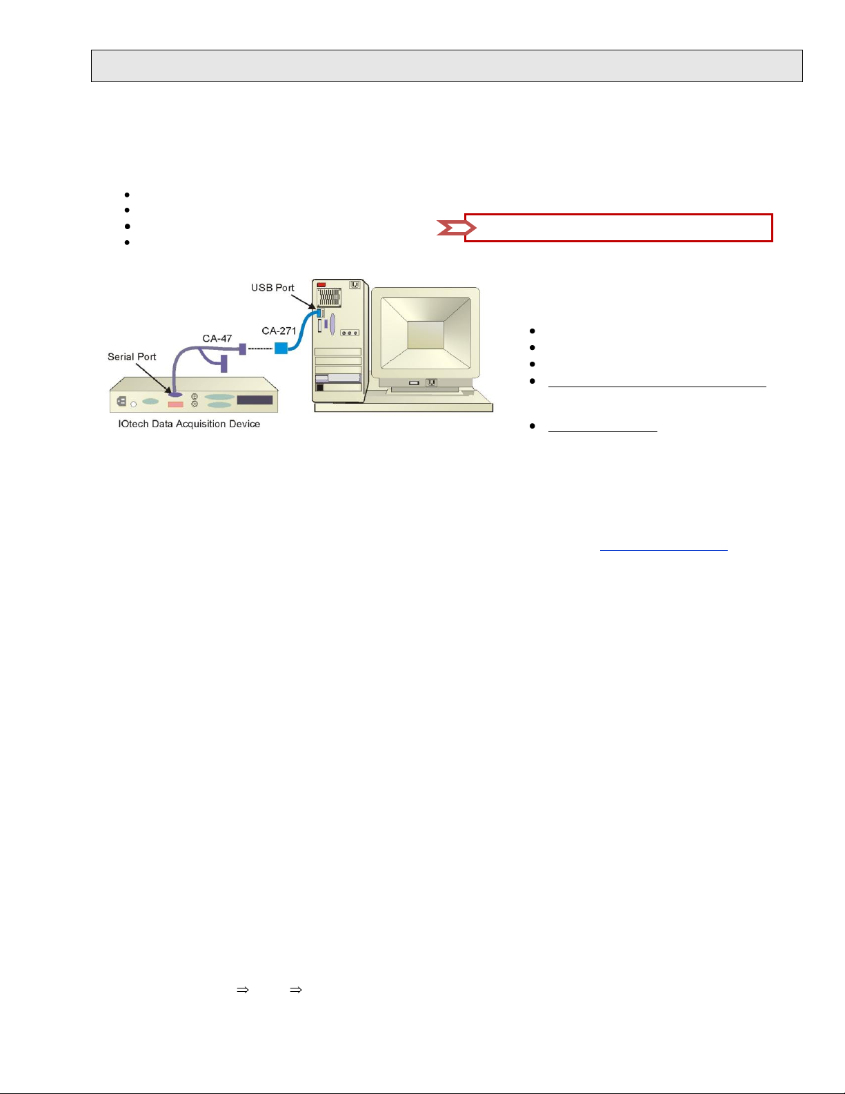
1. Connect the single DB9 end of a CA-47 serial communication cable to
Figure 2. USB Serial Converter (Incorrect)
Figure 3. Selecting Properties for USB Serial Converter
Figure 4. Checking “Load VCP” in the Advanced Tab
Figure 5. USB Serial Port (COM) The desired result.
*325028A-01*
Note: The CA-47 cable has three connectors. Only the two DB9 connectors are used.
The CA-271, like the RS-47 cable, is part of RS-232 to USB Interface Adapter Kit
(CA-232-USB-KIT). Neither item is included in the base device hardware package.
the Serial Port on your data acquisition device.
2. Connect the CA-47 cable to the CA-271 converter cable.
3. Connect the CA-271 converter cable to a USB port on the host PC.
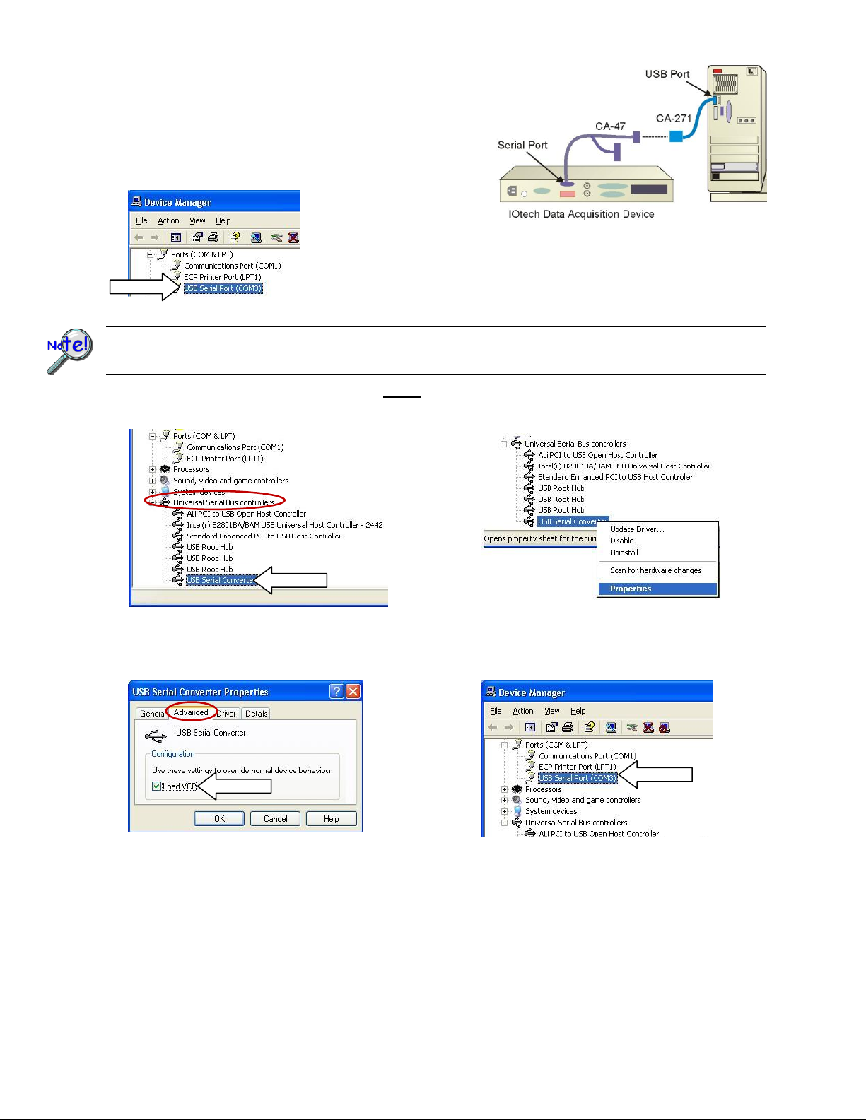
4. In the Device Manager check under Ports (COM & LPT) for the new port;
for example, USB Serial Port (COM3) as seen in Figure 1. If you see the
new port your installation is complete.
Figure 1. The USB Serial Port (Correct)
Some computers will not initially create the USB Serial (COM) as shown in Figure 1. If this is the case with your system
you will see a new “USB Serial Converter” under Universal Serial Bus Controllers as in Figure 2 and will need to follow the
additional steps below.
The following steps are to be followed only if your system did not provide a USB Serial Port (COM) as in Figure 1.
1. In the Device Manager, right click on the USB Serial Converter (Figure 2.) A pop-up menu will appear (Figure 3).
2. Left click on the Properties (Figure 3). A USB Serial Converter Properties dialog box will appear (Figure 4).
3. Select the Advanced tab and check the “Load VCP” box (Figure 4).
4. Disconnect the CA-271 from the PC’s USB port; then reconnect it.
5. Go back to the Device Manager. You should now see the new USB Serial Port (COM), as in Figure 5.
The installation is complete.
 Loading...