

Page 1

PointScan Road Map
For use with “Dedicated” or “Shared” Local Area Networks (LAN)
IOtech, Inc.
25971 Cannon Road
Cleveland, OH 44146-1833
Phone: (440) 439-4091
Fax: (440) 439-4093
E-mail: sales@iotech.com
Internet: www.iotech.com
PointScan Road Map
For use with “Dedicated” or “Shared”
Local Area Networks (LAN)
p/n
1085-0910 Rev. 2.0
877995
Page 2

ii PointScan Road Map
Page 3

Table of Contents
Introduction ...... 1
Dedicated LAN, 2 figures …… 2
Shared LAN, 1 figure …… 3
Step 1) Hook up the PointScan Hardware …… 4
Step 2) Power up the PointScan Hardware …… 5
Step 3) Set up Ethernet Communications . . . …… 6
Step 4) Install the IOToolKit Software …… 7
Step 5) Start up the IOToolKit Software …… 8
Step 6) Configure each Ethernet [PointScan/100 series]
Module using IOToolKit …………………………………… 8
Step 7) Configure each “RS-485 Connected” Module using IOToolKit …… 13
Step 8) Fill in the “Connected To” Information . . . …… 16
Step 9) Download the Configuration to each PointScan Module …… 16
Step 10) Install the KEPServerEX Software …… 20
Step 11) Start up the KEPServerEX Software …… 21
Step 12) Configure KEPServerEX …… 21
Step 13) Configure DASYLab as the Client Program …… 28
PointScan Road Map 897795 iii
Page 4

This page is intentionally blank.
iv 897795 PointScan Road Map
Page 5

Introduction
This document provides a “road map” for setting up a PointScan data acquisition system that is made
up of the following elements:
1. PointScan/100 and PointScan/200 series hardware modules,
2. KEPServerEX server software.
3. DASYLab client software.
This document is called a “road map” because it provides top-level directions to guide the user
through the setup process. Each software package (IOToolKit, KEPServerEX, and DASYLab) provides
more detailed setup information through on-line help screens.
This road map is designed for users who have the following system configuration:
• Both the DASYLab and KEPServerEX software packages are running on the same computer.
• The computer and the PointScan modules are connected using an Ethernet LAN (Local Area
This document covers the setup process for two network cases, (1) “Dedicated” LAN and
(2) “Shared” LAN. For most of the steps the instructions are identical. When differences do exist, the
steps for each case are clearly indicated.
Be sure to follow the steps as applicable to your LAN. If you are uncertain as to whether the LAN is
“Dedicated” or “Shared,” please consult your network administrator. The figures on the following two
pages should clarify any confusion regarding the type of LAN (Dedicated or Shared).
which are configured using the IOToolKit software package.
Network).
PointScan Road Map 878395 1
Page 6
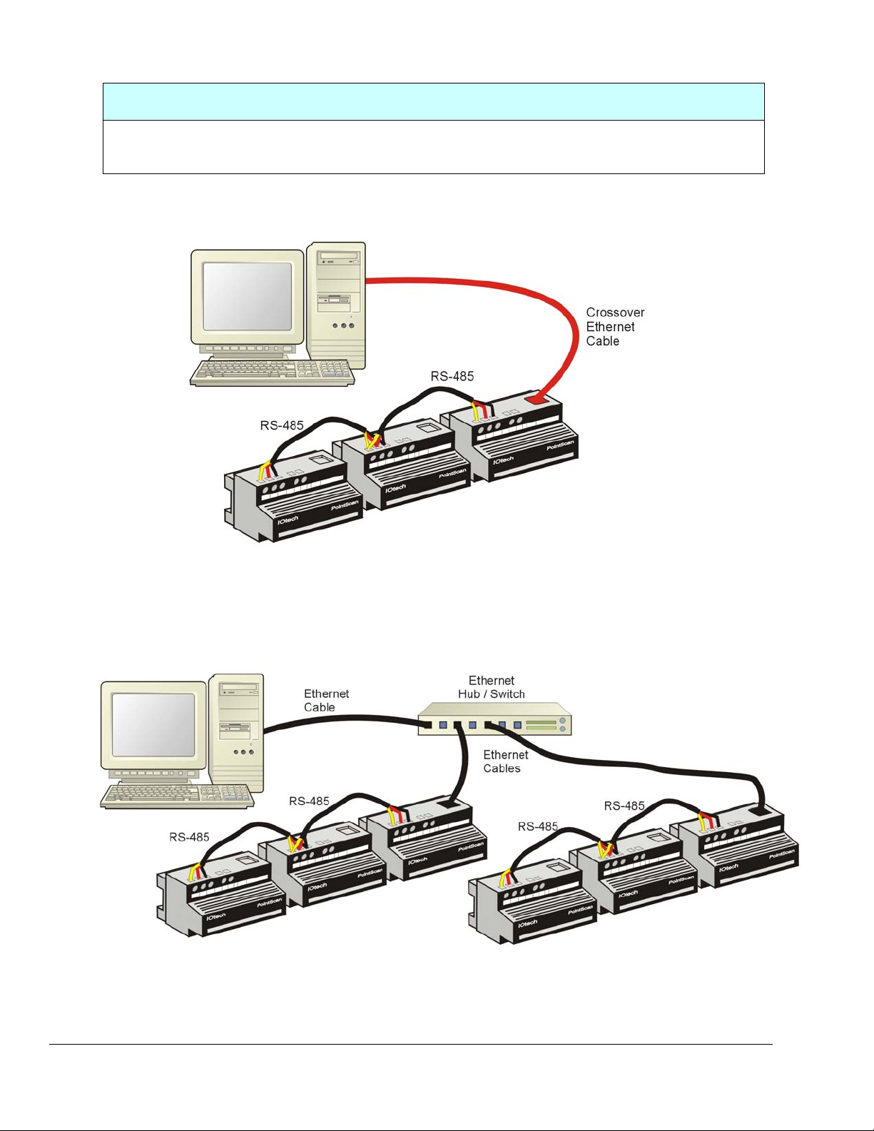
“DEDICATED” LAN
“Dedicated” LAN refers to an Ethernet Local Area Network that is dedicated solely to the PointScan
system and to no other device. The following 2 figures are examples of “Dedicated” LAN setups.
Dedicated LAN, with no HUB/Switch
Note: A “Crossover” Ethernet Cable is used in this setup.
Dedicated LAN, with Ethernet Hub/Switch
Note: Standard Ethernet Cables are used in this setup.
2 878395 PointScan Road Map
Page 7
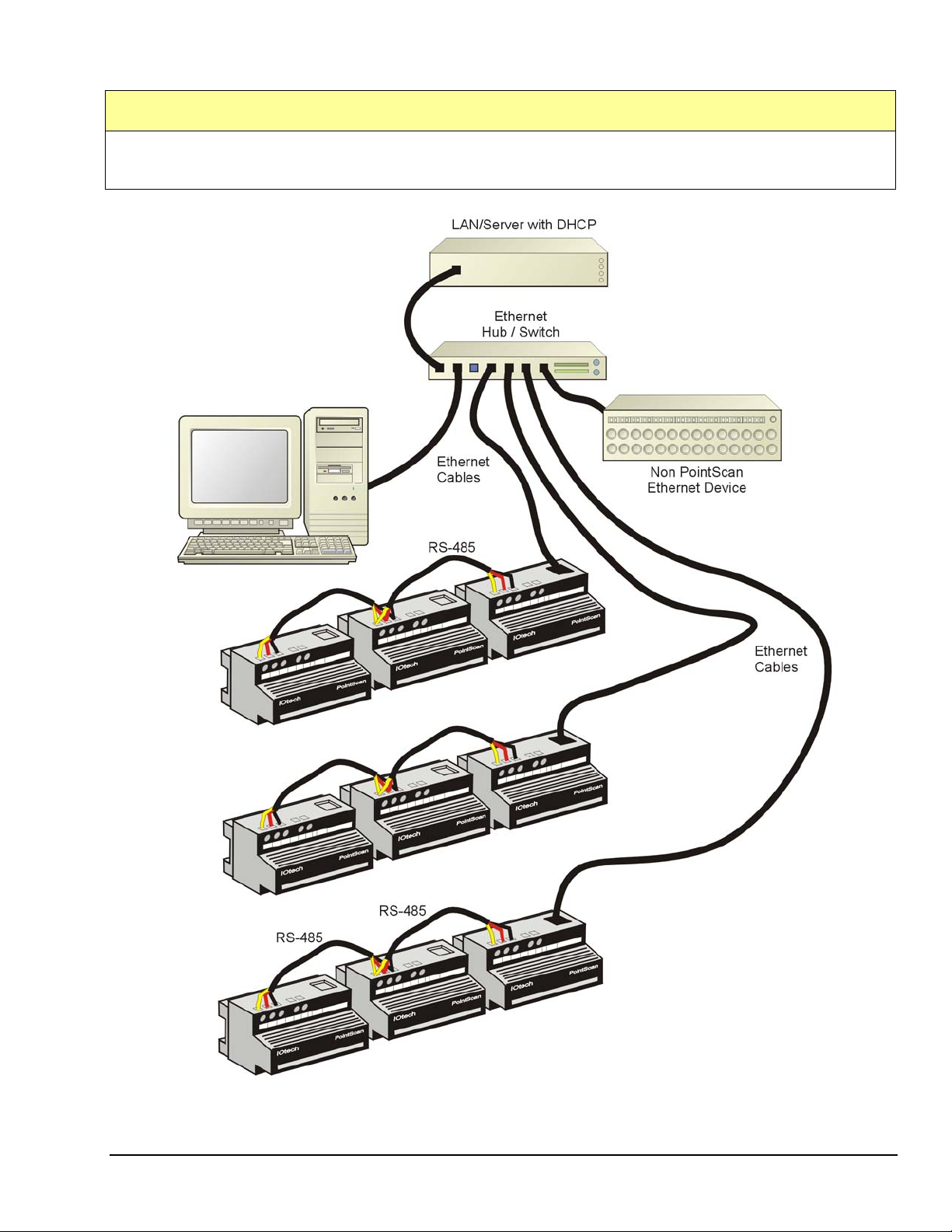
“SHARED” LAN
“Shared” LAN refers to an Ethernet Local Area Network that is used by both the PointScan system and at least
one other non-PointScan device.
Shared LAN
Note: Standard Ethernet Cables are used in this setup.
PointScan Road Map 878395 3
Page 8

Step 1) Hook up the PointScan Hardware
Follow the hardware instructions in the PointScan User Guides to set up the module bases and to
connect sensors to PointScan units. If you do not have a copy of those documents, you can find PDF
versions at our website:
page until you see PointScan manuals.
Two very important hardware configuration steps are located in the PointScan/100 Series User’s
Manual, p/n 1085-0901. The steps can be found on pages 1-2 and 2-1 of that manual, respectively.
(a) Connecting the operating power to the modules.
(b) Connecting RS485 communications wiring between multiple modules.
If you are connecting your computer directly to a single PointScan/100 module,
you need to use an Ethernet crossover cable (instead of a standard one). If you
have more than one /100 series PointScan module in your system, you will need
to use an Ethernet hub or switch to connect the computer and PointScan
hardware to the network.
If you have any PointScan/200 series modules in your system, you must have a
PointScan/440 module to configure them. If this is the case, connect the 440
module to your computer’s serial port.
Never add PointScan modules to an active system, which is communicating with
KEPServer. Prior to adding modules, power-down the on-line modules and stop
the KEPServer communications.
Up to 7 PointScan modules can be powered by one PointScan/443 power supply module. Each
PointScan module requires approximately 140ma of current from the power source. You will need to
budget your available supply power accordingly, especially if you plan on using the same power supply
for external transducers and/or current loops.
Whenever an un-powered PointScan/443 module is plugged-in, it will only
power up to 4 connected modules. Attempting to startup more than 4 modules
will result in a power-stall condition, in which the /443 module cannot produce a
high enough output voltage. However, there are two methods for powering up
more than 4 modules. Both are discussed in step 2, below.
Avoid unnecessary power cycling of PointScan systems, as these systems are
designed to receive a continuous, uninterrupted supply of power. Returning
power to a system of 5, 6, or 7 modules will likely result in a power-stall
condition. Refer to the following step in regard to power start up.
Up to 32 modules using RS485 communications can be daisy chained from the RS485 port of one /100
series module. The /100 series modules provide the connection to Ethernet.
http://www.iotech.com/manuals.html. Simply scroll down the tech manuals
4 878395 PointScan Road Map
Page 9

Step 2) Power up the PointScan Hardware
Up to 7 PointScan modules can be powered from one PointScan/443. However, the same is not true
for system startup. Plugging in a PointScan/443 that supports 5, 6, or 7 modules will most likely
result in a power-stall condition. If your system has 5 or more modules you will need to
employ one of the following methods to power up the entire system.
Method 1 - uses a power output switch:
(a) Ensure that the PointScan/443 is removed from its AC power supply.
(b) Place an on/off switch in the /443’s 24 VDC power output line.
(c) With the switch open [and up to 7 modules connected] supply AC power to the /443.
(d) After the /443 is powered, close the 24 VDC power output switch.
(e) Check the LEDs on the modules to verify their status is normal.
Method 2 - does not make use of a switch:
(a) Ensure that the PointScan/443 is removed from its AC power supply.
(b) Ensure that no more than 4 modules are connected to the system.
(c) Plug the /443 into its AC power supply.
(d) Check the LEDs on the modules to verify their status is normal.
(e) If applicable, connect the additional module(s) one at a time. Make sure that no more
than 7 modules will be connected to a single PointScan/443.
(f) Check the LEDs on the newly added modules to verify their status is normal.
Status LEDs are detailed in the PointScan hardware User’s Manuals.
PointScan Road Map 878395 5
Page 10

Step 3) Set up Ethernet communications between your Computer
and the “Ethernet-Connected” PointScan/100 module(s)
PointScan/100 modules can be used in either an “Ethernet-connected” mode
or an “RS-485 connected” mode.
In this step each PointScan/100 module discussed is used in the
“Ethernet-connected” mode.
Determine the IP addresses for PointScan/100 modules
By default, the PointScan/100 modules are shipped with an IP (Internet Protocol) address of 10.1.0.1.
This address is stored in the base of the /100 module. If your system has only one of these /100 modules
and you have a direct connection from the computer to the /100 module, there is no need to change this IP
address. However, if you have more than one PointScan/100 module take action according to whether
your LAN system is “dedicated” or “shared.”
“DEDICATED” LAN “SHARED” LAN
For “Dedicated” LAN systems: If you have
more than one “Ethernet-connected” PointScan
/100 series module, you will have to change the
IP address of the second and following modules
to 10.1.0.2, 10.1.0.3, and so forth.
See Step 6, part g on Configuring /100 Series
modules using IOToolKit.
For “Shared” LAN systems: You must obtain a
set of unused IP addresses from your network
administrator. Then you must change the IP
address of each “Ethernet-connected” PointScan
/100 series module to one of these unused
addresses.
See Step 6, part g on Configuring /100 Series
modules using IOToolKit.
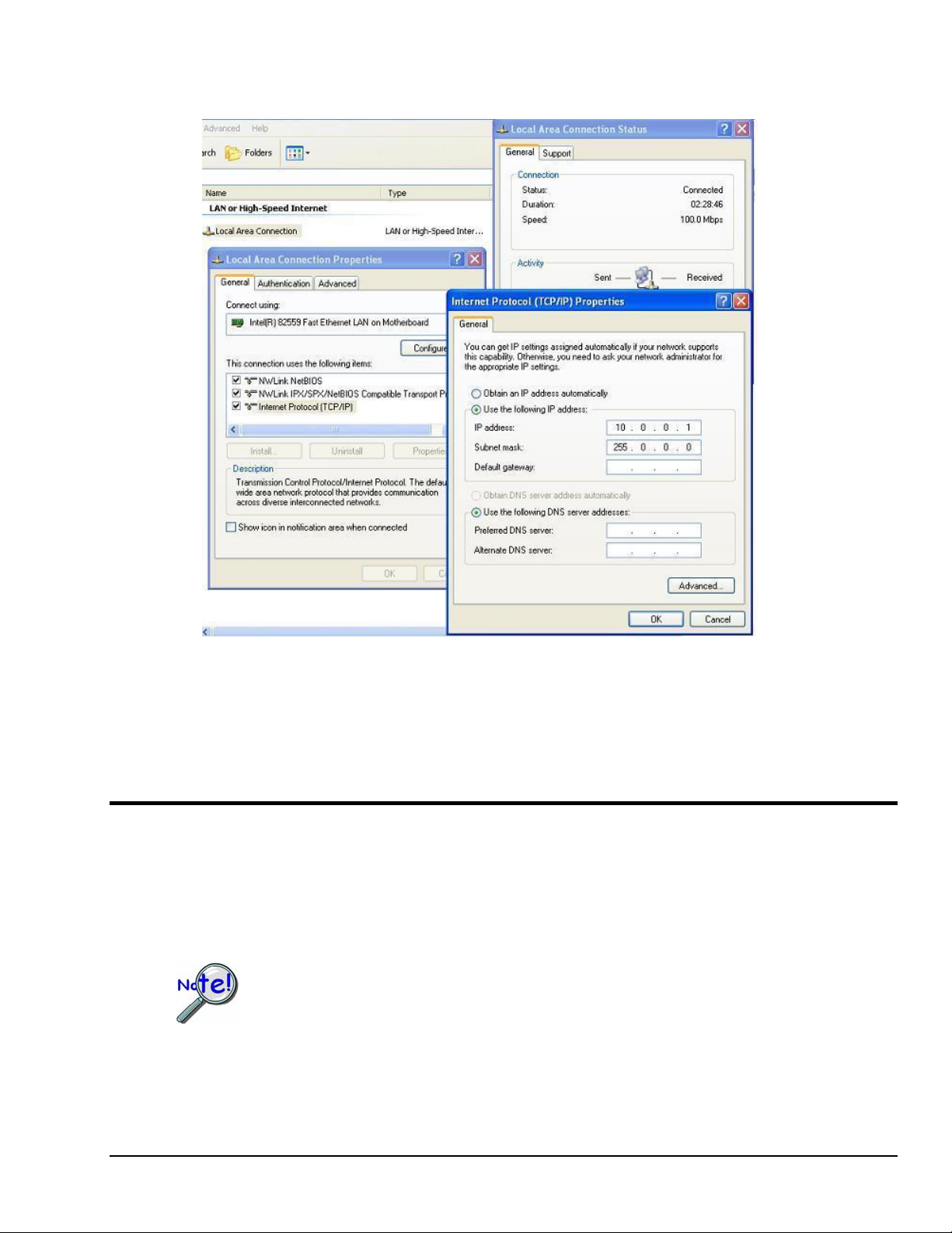
Set up the IP address for your computer
Your computer’s IP address needs to be fixed, not a dynamic one chosen by DHCP or other means.
To set this fixed address to one that is compatible with the PointScan/100 modules:
1) Open the Windows Control Panel and double-click the Network icon.
2) Navigate to the TCP/IP Properties window for the Network Interface card you are using.
3) Select the option labeled “Use the following IP address.”
4) Enter the following numbers for “Dedicated” or “Shared” LAN, as applicable to your
system:
“DEDICATED” LAN “SHARED” LAN
IP Address: 10.0.0.1
Subnet Mask: 255.0.0.0
Use an IP Address and Subnet Mask
provided by the network administrator.
6 878395 PointScan Road Map
Page 11
5) Close out the Network window and the Control Panel. Make sure that you disable any firewall
programs or other software that might restrict traffic on the Ethernet port.
Screens Pertaining to Internet Protocol
IP Address and Subnet Mask shown are for a “Dedicated” LAN. For
”Shared” LAN obtain IP Address and Subnet Mask values from your
network administrator.
Step 4) Install the IOToolKit Software
(a) Insert the IOToolKit CD (p/n 1075-0601) into the CD drive on your computer. If the CD does not
auto-start use Windows Explorer to browse to the contents of your CD drive. Then, open the IO
Tools Install folder and double-click on the Setup.exe file [in that folder].
(b) Follow the prompts to complete the installation.
At some point after the installation you need to register your IOToolkit software.
This is done from the IOToolkit Help>Registration Window.
PointScan Road Map 878395 7
Page 12

Step 5) Start up the IOToolKit Software
Start the IOToolKit by going to the Windows Start menu and then selecting Programs > IO Tools.
The IOToolKit is used to set up the configuration of each PointScan module in the system. It also
downloads the configuration to the module base.
Step 6) Configure each Ethernet [PointScan/100 Series] Module
using IOToolKit
Most of the IOToolKit windows have a Help button you can press if you are not sure how to select some of the
parameters.
(a) Start the configuration process by running the Plug and Play Wizard in IOToolKit. You do this by
selecting Tools, then Plug and Play Wizard; or by clicking on the Playing Card icon.
(b) Select <Add a new station to the project> and click <OK>.
(c) Select the type of module to be added. Note that the PointScan/100 series modules are all of the
Ethernet I/O Module type.
(d) If this is the first module you are adding to the project, IOToolKit will ask you to save the
configuration as a Project File. Select a file name (use the extension *.6pj) and click <Save> to
save the project file away.
TIP: Perform the File/Save Project action several times during the configuration
process to ensure the project is saved with your most recent configuration
settings.
(e) Fill in the parameters in the General tab, then click <Next>:
Station type – Select the PointScan/100 series module being used.
Station name – Any alphanumeric string up to 20 characters can be used.
Serial number – use the serial number printed on the front of the base of the /100 series
module, just above the power wiring.
Station number – start with number 1, then increment for other stations in the system,
whether /100 or /200 level stations. It is very important that the station number is set
correctly when you have multiple modules interconnected using RS485. The station
number must correspond with the number that represents the module’s position in the
RS485 link. The first module that connects to Ethernet is always station one, and each
additional module that is connected using RS485 takes the next consecutive station
number in order.
Com timeout – 3 seconds is usually adequate (click on Help for more info)
8 878395 PointScan Road Map
Page 13

Remote I/O Configuration, General Tab
(f) Fill in the fields in the RS-485 tab (following figure), then click <Next>.
This tab (following figure) refers to the RS-485 port on the /100 series module.
Therefore, it needs to be filled-in
modules connected to it via the RS-485 link. These “other” modules can be either
/200 series or /100 series [used in “RS-485” mode].
only if the /100 series module has other
Protocol - Select <Modbus ASCII Passthru>.
Baud Rate – A value of 9600 is adequate for most purposes. However, you may need to use a
higher baud rate, especially if you are connecting a large number of modules using the RS-485
link.
All interconnected modules must be set to the same baud rate.
Mode, Lead Time, Lag Time - Accept the defaults (click on the Help button for more information
on these parameters).
Timeout - Recommended value is 0.3 seconds
Remote I/O Configuration, RS-485 Tab
PointScan Road Map 878395 9
Page 14

(g) Fill in the fields on the “Ethernet” tab (following figure) for “Dedicated” LAN or “Shared” LAN, as
applicable to your setup. Then click <Next>.
“DEDICATED” LAN “SHARED” LAN
• ONLY IF the default address of 10.1.0.1 is
acceptable select <Use this IP address>.
This is the case if the module being
configured is the first or only “Ethernetconnected” /100 series module in the
system.
• If the default address is not acceptable
select <Specify an IP address>. This is
the case if the module being configured is
not the first or is not the only “Ethernetconnected” /100 series module in the
system. If it is the second “Ethernetconnected” module, you should enter the
address of 10.1.0.2; if it is the third, then
enter 10.1.0.3, and so forth.
• Primary Protocol - select Modbus
• Advanced Settings - click on this button,
then enter a subnet mask number of
255.0.0.0 You should do this whether or
not you are changing the module IP address
from the default one of 10.1.0.1. Leave all
other parameters at their default values.
• Click on <OK> when you are done.
• Select <Specify an IP address>. Since the
system is part of a shared LAN network you
will need to change the module’s IP address to
an unused one [provided by your network
administrator].
• Enter the IP address [provided by your
network administrator].
• Primary Protocol - select Modbus
• Advanced Settings - click on this button,
then enter a subnet mask number which was
provided by your network administrator.Leave
all other parameters at their default values.
• Click on <OK> when you are done.
Remote I/O Configuration, Ethernet Tab
You must assign a unique IP address to each PointScan/100 Series module. In
other words, no two modules can have the same IP address. This holds true,
regardless of whether a module is “Ethernet-connected” or “RS 485 connected.”
10 878395 PointScan Road Map
Page 15

(h) Fill in the blanks in the Discrete or Analog tab, then click <Finish>.
Some points of importance pertaining to PointScan/100 Series systems:
Which tab is used [Discrete or Analog] depends on the type of /100 series module that
you are configuring.
For information on how to set the parameters, click on the <Help> button.
Disable all unused channels.
You can select a unique tag name for each channel. These tag names will be used by
KEPServer and DASYLab to identify the channels when creating your final program.
Do not change the I/O address. This is the standard addressing scheme used by the
Modbus protocol. These addresses will be used by KEPServer to access the data from the
PointScan modules.
Each PointScan module can have different selections under the “features” column. Refer to
your specific type of PointScan module for available features. You can select or change any
available features on a per channel basis.
The Range column can be set on a per channel basis. Pick the measurement range that is
best suited for your particular application.
Some PointScan modules are capable of several different scan rate settings. You can select
the module scan rate setting that is most appropriate for your application. It is
recommended that you select the same scan rate for all modules in your system. You
should configure the modules for the fastest sample rate that you ever expect to need and
then you can use a method in DASYLab to discard readings to effectively create a lower
sample rate for the modules of your choice.
Scaling is typically done using KEPServer or DASYLab. You should not make any changes
under the Scaling Parameter tab in IOToolKit.
It is important to note that all thermocouple inputs are in Engineering Units (EU)
of degrees Celsius or Fahrenheit, depending on the “Temperature Reporting”
selection. If you select 0.1°C or 0.1°F the reading generated by the module will
be a whole number 10 times greater than the actual value. If this is the case
you will need to scale down the value by a factor of 10 in KEPServer or
DASYLab.
All voltage and current inputs are in raw A/D converter counts. Therefore, the
voltage and current inputs must be scaled to Engineering Units in KEPServer or
DASYLab by converting them to floating point numbers.
PointScan Road Map 878395 11
Page 16

Remote I/O Configuration, Analog Tab
(i) Save the project by going to File/Save Project.
12 878395 PointScan Road Map
Page 17

Step 7) Configure each “RS-485 Connected” Module using IOToolKit
Two “RS-485 Connected” and One “Ethernet-Connected” Module
Providing one cluster of channels over the internet via a single IP Address
An “RS-485 connected” PointScan module can be a /200 Series or a /100 Series
module. In both cases “RS-485 connected” modules serve as expansion devices
for the “Ethernet-connected” PointScan/100 module which resides at the head of
the RS-485 link (see preceding figure).
From software and communication viewpoints, the entire set of modules appears
as one cluster of channels, accessible over the Ethernet via a single IP Address.
To configure the “RS-485 connected” modules:
(a) Start the configuration process by running the Plug and Play Wizard in IOToolKit. You do this by
selecting Tools, then Plug and Play Wizard; or by clicking on the Playing Card icon.
(b) Select <Add a new station to the project> and click <OK>.
(c) Select the type of module to be added. Select “RS-485 I/O Module type” regardless of whether
the module is a /200 series or /100 series [in RS-485 mode].
(d) Fill in the parameters on the General tab [in the Remote I/O Configuration window]
then click <Next>:
• Station type – Select the PointScan/100 or /200 series module being used.
• Station name – Any alphanumeric string up to 20 characters can be used.
• Serial number – use the serial number on the base of the /100 or /200 series module.
• Station number – must be a unique number in the total PointScan system. It is very
important that the station number is set correctly when you have multiple modules
interconnected using RS485. The station number must correspond with the number that
represents the module’s position in the RS485 link. The first module that connects to
Ethernet is always station one, and each additional module that is connected using RS485
takes the next consecutive station number in order.
• Com timeout – 3 seconds is usually adequate (click on Help for more info)
PointScan Road Map 878395 13
Page 18

Remote I/O Configuration, General Tab
(e) Fill in the “Define RS-485 Communications for this Station” fields in the RS-485 tab, then click
<Next>. See following figure.
Information in the following figure [Remote I/O Configuration, RS-485 tab] refers to the RS-485 port
on the “RS-485 connected” module.
Protocol -
- For a /100 Series Module: Select <ModBus ASCII Slave>
- For a /200 Series module: Select <Modbus ASCII>.
Baud Rate - Needs to match the baud rate of the RS-485 link on the “Ethernet-
connected” /100 series module to which it is connected.
Mode, Lead Time, Lag Time - Accept the defaults. Click <Help> for more information.
Remote I/O Configuration, RS-485 Tab
14 878395 PointScan Road Map
Page 19

(f) Fill in the fields in the Discrete or Analog tab, then click <Finish>.
Some points of importance pertaining to PointScan/100 and /200 Series systems:
The tab used [Discrete or Analog] depends on the type of module that you are configuring.
For information on how to set the parameters, click on the <Help> button.
Disable all unused channels.
You can select a unique tag name for each of channel. These tag names will be used by
KEPServer and DASYLab to identify the channels when creating your final program.
Do not change the I/O address. This is the standard addressing scheme used by the
Modbus protocol. These addresses will be used by KEPServer to access the data from the
PointScan modules.
Each PointScan module can have different selections under the “features” column. Refer to
your specific type of PointScan module for available features. You can select or change any
available features on a per channel basis.
The Range column can be set on a per channel basis. Pick the measurement range that is
best suited for your particular application.
There are PointScan modules that are capable of several different scan rate settings. You
can select the module scan rate setting that is most appropriate for your application. It is
recommended that you select the same scan rate for all modules in your system. You
should configure the modules for the fastest sample rate that you ever expect to need and
then you can use a method in DASYLab to discard readings to effectively create a lower
sample rate for the modules of your choice.
Scaling is typically done using KEPServer or DASYLab. You should not make any changes
under the Scaling Parameter tab in IOToolKit.
It is important to note that all thermocouple inputs are in Engineering Units (EU)
of degrees Celsius or Fahrenheit, depending on the “Temperature Reporting”
selection. If you select 0.1°C or 0.1°F the reading generated by the module will
be a whole number 10 times greater than the actual value. If this is the case you
will need to scale down the value by a factor of 10 in KEPServer or DASYLab.
All voltage and current inputs are in raw A/D converter counts. Therefore, the
voltage and current inputs must be scaled to Engineering Units in KEPServer or
DASYLab by converting them to floating point numbers.
Remote I/O Configuration, Analog Tab
(g) Save the project by going to “File/Save Project”.
PointScan Road Map 878395 15
Page 20

Step 8) Fill in the “Connected To” Information in the Station Tab in
the IOToolKit Main Window
(a) Click on the Stations tab in the IOToolKit main window.
(b) Set the “Connected To” parameter for each “Ethernet-connected” /100 series module to “Ethernet
Remote I/O Station.”
(c) Set the “Connected To” parameter for each “RS-485 connected” module to “Ethernet I/O
Expander.”
(d) Set the Station Name to the "Ethernet-connected" /100 series module to which it is connected.
(e) Set the Port Type to RS-485.
Selecting the Connection Type for a PointScan204
(f) Save the project using “File/Save Project”.
Step 9) Download the Configuration to each PointScan Module
Download the Configuration for /100 Series “Ethernet-Connected” Modules
You can download the configuration to the /100 series modules using the Ethernet connection between
the computer and the modules. However, keep in mind that you can connect only
module at a time to the network when you are downloading configuration information to that module.
In both instances, i.e., for “dedicated” and “shared” networks:
a) Click on the Ethernet Device icon.
b) Go to Device/Select (or click on the Select Device icon).
c) Ensure the parameters are set as follows:
o Use Ethernet
o Connection = Network/Passthru
o Timeout = 3000 mS
o IP Address: Use “Specify an IP Address” and enter the current IP Address for the station. If
you want to change the IP Address you need to enter the new address in the module
configuration as described in Step 6g.
one /100 series
Each PointScan/100 module has a factory default IP Address of 10.1.0.1. If you
have changed that address, e.g., during a configuration download, then you will
have to enter that new address. If you are not sure as to what the new address
is, you can use the “Find Ethernet Status” utility [binoculars icon] to learn what
the current IP Address is.
d) Click <OK> to close the Select Communication Device window.
e) Highlight the first “Ethernet-connected” PointScan/100 series module in the Tree View.
16 878395 PointScan Road Map
Page 21

f) Select: Operations> Load> Load Now (or click on the Load icon) to download the configuration to
this module.
You should get a message that the download has been completed successfully. If there are other
“Ethernet-connected” /100 series modules in your system, do the same for each.
Remember to disconnect the previous /100 series module before you connect the next one.
Set Communications Device
Shown with the default IP Address.
IOToolKit Screen, Location of the <DownLoad> Button
PointScan Road Map 878395 17
Page 22

Download the Configuration for ”RS-485 Connected” Modules
These instructions pertain to “RS-485 connected” modules. These can be PointScan/200 Series,
PointScan/100 Series [in RS-485 mode], or a combination of the two types of modules.
When you are using PointScan/200 Series modules or a combination of
PointScan/100 Series and /200 Series modules, a PointScan/440 Serial
Interface Module is required to perform the download function.
If the “RS-485 connected” modules consist only of PointScan/100 modules a
PointScan/440 is not required. In this case you can perform the download over
the Ethernet one module at a time. To do this:
Perform Step 7 (for configuring the module in IOToolKit)
Follow the download instructions for “Ethernet-connected”
/100 Series modules per Step 9.
Complete all downloads.
Skip to Step 10 and continue the setup process.
Downloading the configuration to “RS-485 connected” modules is done using the serial connection
between the computer and the modules.
Note that the following steps [a through j] are performed for one module at a time. They are then
repeated for each additional “RS-485 connected” module.
Setup the hardware:
THIS POINTSCAN/440 SETUP METHOD MAY NOT APPLY TO YOUR SYSTEM. IF YOU
ARE NOT SURE OF /440 APPLICABILITY, RE-READ THE PRECEDING NOTE BEFORE
CONTINUING.
(a) Remove the applicable “RS-485 connected” module from its base. This can be done while
the PointScan system is still powered.
(b) Install a PointScan/440 module in its place. Make sure that you have the cable connected
between the /440 module and your computer’s serial port.
Verify that parameters are properly set:
(c) Click on the Com Port Device icon.
(d) Go to Device/Select [or click on the Select Device icon]. The Select Communications
Device window (following figure) will appear.
(e) Verify that the parameters are set as follows. Change the settings as required.
• Connection: Single station
• Port: use Com Port
• Com port: COM1 (or whichever serial port you are using on your computer)
• Baud rate:9600 (default - or match computer port setting)
Parity: None (default - or match computer port setting)
•
• Data bits: 8 bit binary/RTU data (default - or match computer port setti
• Stop bits: 1 (default - or match computer port setting)
• Flow control: None (default - or match computer port setting). Note that some
USB-to-Serial Port converters may require Xon/Xoff Flow control to be enabled.
• Timeout: 3000 mS
• Test I/O default protocol: I/O for Windows
(f) Click <OK> to close the Select Communication Device window.
ng)
18 878395 PointScan Road Map
Page 23

Select Communications Device
For more information on these settings, click on the <Help> button in the IOToolKit window.
Download the configuration:
Note: You will not be able to download a configuration to a module if you have incorrectly
entered the module’s serial number in the IOToolKit setup screen.
(g) In the Tree View, highlight the “RS-485 connected” module that you are configuring.
(h) Select Operations> Load> Load Now (or click on the Load icon) to download the configuration
to this module. You should get a message that the download has been completed
successfully. If you get a firmware upgrade Error Message “SVCFGRIO,” click <Yes>.
(i) After successful completion of the Download, remove the PointScan/440 module from the base
and replace it with the “RS-485-connected” module previously removed.
Repeat the steps for additional “RS-485 connected” modules:
If applicable, repeat steps “a” through “j” for each additional “RS-485 connected” module.
IOToolKit Screen, A PointScan/204 is Selected
PointScan Road Map 878395 19
Page 24

Step 10) Install the KEPServerEX Software
Note: If you have purchased the LITE version of KEPServer you will be allowed to configure your
server to communicate with up to a maximum of 4 PointScan modules.
After you purchased the KEPServerEX software license, you should have received a green Kepware CD
that is packaged inside a green and gold plastic container. There should be a Kepware software
license number and an IOTech PointScan /100 license number printed on the inside front cover of the
plastic container. Also, the plastic container should include a 16-page product information booklet
that tells you how to install the KEPServer license. Read pages one through four for detailed
installation instructions. These instructions can be summarized as follows:
(a) Insert the Kepware CD into the CD drive on your computer. This needs to be the same PC
that will be connected to the PointScan modules and will be running DASYLab.
Note: Inserting the CD should auto-start the installation process. If the CD does not auto-
start, use Windows Explorer to browse to the contents of your CD drive. Then, find
the KEPServerEX_Install \ Disk1 folder on the CD and double-click on the
Setup.exe file [in that folder].
(b) Follow the prompts to complete the installation.
Note: Make sure that you select
installation. Do not select all drivers or you may run into problems later on.
only the IOtech PointScan100 driver when you do the
Kepware Setup Utility Screen
(c) After completing the installation of KEPServerEX, go to the Kepware product information
booklet and follow the instructions for Licensing and Registering a Driver.
Until you register the driver you will not be able to run KEPServer
for more than 2 hours.
20 878395 PointScan Road Map
Page 25

Step 11) Start up the KEPServerEX Software
The KEPServerEX software is used to set up and implement an OPC server. This server automatically
polls the PointScan modules and updates its data base with the current value of the process variables
monitored by those modules. Information in that data base can then be accessed by compatible OPC
clients, such as DASYLab or Kepware’s Quick Client.
General information on KEPServerEX is available on the Kepware CD. Insert the CD in the drive and
let it auto-start as described in Step 10). Then click on the “Product Specifications” menu item and
select KEPServerEX from the list. The system will show you several pages of general information
about the features and operation of KEPServerEX.
For more detailed instructions on configuring KEPServerEX, close out the Product Specifications
window and click on the Menu button to bring up the first menu on the Kepware CD. Click on the
“Product Support” selection and you will see several useful documents, including a Quick Start Guide,
an Installation Guide, and a KEPServerEX Help Manual under the White Papers option.
To start up and run the KEPServerEX software, go to the Windows Start menu, select the KepWare
Products program group, and then click on KEPServerEX.
The following steps show how to configure KEPServerEX specifically for PointScan/100 and /200 type
modules. They include information on how to:
• add station names and channel tag names
• specify device IP addresses and channel Modbus addresses
• prove the IO communication with all devices using the OPC <QuickClient> button
• save the configuration for backup purposes
Note: In any of the KEPServerEX configuration windows, you can always click on the
<Help> button for more information on how to fill out the forms.
Step 12) Configure KEPServerEX
Adding a KEPServerEX “Channel”
The first step in the configuration process is to create a new KEPServerEX “Channel.” Note that the
word “channel” in this context means a communications channel or driver, not a process input such as
a thermocouple input or voltage input channel. The steps are:
(a) Click on the “Click to add a channel” link in the upper left hand portion of the
KEPServerEX window.
(b) In the “New Channel - Identification” window either accept the default channel name, or
enter a new one, then click on <Next>. Note that the name must not exceed 256
characters.
TIP: Change the name to something other than “channel.” A meaningful
channel name will stop confusion from occurring when accessing the
actual channel tags through DASYLab. A good idea is to use a project
name, for example, “Test_Lab_Monitor.”
(c) In the “New Channel - Device Driver” window, make sure that the “IOtech PointScan
/100” device driver is selected. Then click on Next.
PointScan Road Map 878395 21
Page 26

If the IOtech PointScan100 driver is not listed in the pulldown menu, there
has been an installation error. If this is the case you must uninstall and
reinstall the KEPServerEX software, taking care to include the IOtech
PointScan100 driver in the installation.
(d) In the “New Channel - Network Interface” window, you can leave the selection at
“Default” if you have only one network interface card (NIC) installed in your computer. If
you have multiple NICs installed, you must select the NIC that communicates with the
PointScan hardware in your system. Then click on Next.
(e) In the “New Channel - Write Optimizations” window, you can accept all of the default
parameters and click on Next.
(f) In the “New Channel - Summary” window, review the information for correctness and then
click on Finish.
(g) Select File>Save As to create a KEPServerEX project file for your current system.
New Channel Device Driver Screen
New Channel Summary Screen
22 878395 PointScan Road Map
Page 27

Adding a KEPServerEX Device
In KEPServerEX, a “device” is a single PointScan module (either a PoinScan/100 series device or a
PointScan/200 series device). The steps for adding a device to a KEPServer “channel” are as follows:
(a) Click on the “New Device” button in the upper left hand portion of the KEPServerEX
window. See following figure.
Clicking on the “New Device” Button
(b) In the “New Device - Name” window, enter a device name that follows the stated
guidelines and then click on Next.
(c) In the “New Device - ID” window, enter the following, then click on Next:
If the device is a /100 series PointScan module that is connected to the Ethernet,
enter the IP address of the module that you configured in IOToolKit.
Example for “Dedicated” LAN: 10.1.0.1
Example for “Shared” LAN: 63.66.249.202
In both the “Dedicated” and “Shared” LAN examples, the PointScan/100 series
module was configured as Station 1 in IOToolKit.
If the device is a /200 series PointScan module [or a /100 series module
connected via RS485 communications], enter the IP address of the /100 series
Ethernet module to which it is connected, followed by a decimal point and the
device station number of the module that you configured in IOToolKit
Example for “Dedicated” LAN: 10.1.0.1.2
Example for “Shared” LAN: 63.66.249.202.2
In both the “Dedicated” and “Shared” LAN examples, the “.2” signifies that the
PointScan module is station number 2 in a string of modules connected via RS485.
(d) In the “New Device - Communication Parameters” window, accept the default parameters
and click on <Next>.
(e) In the “New Device - TCP/IP” window, accept the default port number and click on
<Next>.
(f) In the “New Device - Block Sizes” window, accept the default parameters and click on
<Next>.
(g) In the “New Device - Summary” window, review the information for correctness and then
click on <Finish>.
PointScan Road Map 878395 23
Page 28

Adding a KEPServerEX Static Tag
In KEPServerEX, a “static tag” represents a single input to a PointScan module (either a PoinScan/100
series device or a PointScan/200 series device).
Note: The word “tag” is frequently used in the industrial automation and control industries and is
common terminology with OPC server software packages.
TIP: Since, each tag applies to one specific input [or output] that is connected to a
PointScan module, think of each tag as a “per-channel” text name.
The steps for adding a static tag to a KEPServer device are:
(a) Click on the “Click to add a static tag” link in the upper right hand portion of the
KEPServerEX window.
(b) In the General tab section of the “Tag Properties” window (next figure), fill in the
parameters for the first tag as follows:
Tag Properties, General Tab
Name - Any alphanumeric string up to 256 characters can be used. However, you should keep
the names as short as possible since they must fit in various displays. It is important to give each
channel a name that will allow you to recognize it in DASYLab and know which physical input or
output signal channel it represents on the PointScan module. You should take the time to plan out
a naming scheme that will allow you to easily identify channels by their tag names. This is
especially important for systems that have large channel counts.
To automatically create new tag names use the KEPServerEX “duplicate tag”
utility. To use this feature end the tag name with a number.
24 878395 PointScan Road Map
Page 29

Address - Click on the <?> (Hints) button and then the Hints window’s <Help> button for
detailed information on how to set the address. The IOtech PointScan hardware manuals provide
detailed MODBUS addressing information for each individual module type. For example, the
screen indicates that for Analog input you would use addresses in the range 300001 to 330000;
and for Discrete input you would use addresses in the range 100001 to 200000. The IOtech
PointScan modules use standard MODBUS addressing for I/O; however, KEPServer requires that
an additional (0) zero be placed in the MODBUS addressing scheme. The KEPServer address is a
factor of 10 higher than the standard MODBUS address for that I/O type and channel.
Example: The MODBUS address of the third analog input channel on a PointScan /100 series
module is 30003. You will enter 300003 as the address for that tag in KEPServer.
The tag address must be unique within each PointScan module. So if you have a second
PointScan module with analog inputs, you would start over again with address 300001.
Description - This is a comment field (not required). Any alphanumeric string up to 64 characters
can be used.
Data Type - If the OPC client is DASYLab, then the process variables in KEPServer must be
configured for short data format, since DASYLab can recognize
only the short data format.
Client Access - If the tag is an analog or digital input, then Client Access should be set to Read-
Only. If the tag is an analog or digital output, then Client Access should be set to Read/Write.
Scan Rate - Leave this parameter at the default value of 100 milliseconds. This represents an
optimized system in which KEPServer will poll data from the PointScan modules as fast as possible
and DASYLab can be used to control which data points are processed and which data points are
thrown away.
(c) If desired, select the Scaling tab to setup linear scaling values for your data.
Note: It is possible to apply scaling to your data from within DASYLab using DASYLab’s own scaling
module. If you prefer to perform this operation in DASYLab you can disregard the settings under
the scaling tab in KEPServer.
Tag Properties, Scaling Tab
An example of scaling for a thermocouple.
PointScan Road Map 878395 25
Page 30

c.1 After you have selected the Scaling tab, select the radio button labeled “Linear.” See
preceding figure.
c.2 Type in the raw value range for the particular channel type you are configuring. You
can find the raw data ranges in the IOToolKit project configured earlier.
Note: The ranges are located in the Scaling tab in the IOToolKit project. The project
is located under the analog or discrete setup screen. IOToolKit’s Scaling tab
shows the raw minimum (Low) and raw maximum (High) values for PointScan
outputs. The same values are to be placed in the Low and High fields under the
KEPServer Scaling tab. This is true for each tag you are configuring.
The values for the Raw
Range (see figure at
right) are obtained from
the IOToolKit project,
which was previously
configured.
Tag Properties, Scaling Tab
An example of scaling for voltage.
c.3 Fill in the Scaled Value Range values. Select “Float” as the data type from the pull
down list and then enter the desired minimum (Low) and maximum (High) values that
you would like to apply to the raw data from the PointScan module.
c.4 After you have entered all of the parameters in the General and Scaling windows for
the first tag, click on the <Apply> button at the bottom of the window.
c.5 Enter parameters for additional tags in one of two ways:
Click on the “New” tag icon to save the previous tag information and bring up blank
fields for the next tag.
- or –
Click on the “Duplicate” tag icon to copy the previous tag information for the current
tag, but increment any trailing numeric values by one.
For more information on how to select the tag parameters, click on the <Help> button in the
lower right corner of the Tag Properties window.
26 878395 PointScan Road Map
Page 31

Running the “Quick Client” Program
Kepware provides a program called “Quick Client” to allow you to test the configuration and make sure
that KEPServerEX can communicate with the PointScan modules and gather valid data. To run Quick
Client, do the following:
(a) In the KEPServerEX main window, either select Tools>Launch OPC QuickClient or click on
the Quick Client icon (looks like a hammer) at the right end of the icons in the toolbar.
(b) In the OPC Quick Client window, highlight one of the PointScan devices in the upper left
hand part of the window. Note that the entries with a “_System” at the end of their label
are
not actual devices but are system entities. So don’t highlight them.
(c) After you have selected a PointScan device, look at the information in the upper right
hand part of the window. Each row of information represents a single tag in the selected
device. The Item ID column shows the associated name of each tag. The Quality column
for each tag should read “Good” if KEPServerEX is communicating properly with the
selected device. Also, the Value column should display the correct current value of the
input associated with that tag. Remember that if you have chosen
KEPServer, the raw readings will not have a decimal point shown in the display.
not to apply scaling in
OPC Quick Client
You should highlight each device in sequence, checking to make sure that the Quality and
Value parameters for each tag are legitimate. If they are not, you will need to review the
setup windows for each problem device and tag in KEPServerEX to find the source of the
problem.
(d) After you are done running Quick Client, use File>Exit to close out the program. You do
not need to save the changes to the Quick Client program because you will run a fresh
version of this test program each time.
PointScan Road Map 878395 27
Page 32

Step 13) Configure DASYLab as the Client Program
Install DASYLab
DASYLab software versions that precede 6.0 do not support
PointScan products. If your DASYLab version precedes 6.0, please
contact
For DASYLab to properly install, the host computer must be using
Internet Explorer version 5.0 or higher.
Install DASYLab as follows:
(a) Launch the DASYLab installation from the DASYLab CD.
Note: The CD should auto-start. If the CD does not auto-start, run the CD start.exe
from the Windows Desktop.
(b) Select “Installation,” then “Full Version.” The actual installation process will begin.
(c) When prompted for your name, company and serial number, enter the requested data.
Obtain the serial number from the CD jacket.
TIP: Keep the serial number in a safe place. You may need to reference it
for future installations and upgrades.
(d) When prompted for the installation directory and program folder, you can use the default
selection, or choose another. We recommend using the default.
(e) When prompted for Setup Type, choose from the available options. We recommend
that you select Typical.
(f) When prompted to select the drivers, “uncheck” all selections, then click <Next>.
There are no PointScan related drivers to select. The drivers that are
selected in step 6 are for components that are in addition to PointScan.
sales@iotech.com for upgrade information.
28 878395 PointScan Road Map
Page 33

A Word About Data Socket Module Support
This section is only for users who have grayed-out Data Socket Import and Data Socket Export
modules [located in the DASYLab Modules Menu]. This scenario is an indication that the “Data
Socket Module” support did not properly install during the initial installation of DASYLab. If
this is the case you must re-install DASYLab and ensure that the Data Socket Module” support
gets installed. The following screen shots will key you in on what to look for to ensure that
Data Socket Module Support gets installed.
DataSocket Module Must be Selected
When running the NI Data Socket Setup from the DASYLab install you will be prompted to
select components to install. You must have a checkmark in the “DataSocket Module”
selection, located under Program Files. See the preceding figure.
PointScan Road Map 878395 29
Page 34

Choosing a DataSocket Source Folder
You will be prompted to choose a source folder for the DataSocket, as indicated in
the above figure.
Confirmation of Data Socket Support
The NI DataSocket Setup screen prompts you to “select features.” Under Feature
Description you will notice the statement, “DLLs required for DataSocket.” You will also
notice a statement that the feature will be installed on the local hard-drive, and how much
memory is required. This information confirms that the setup application is ready to install
Data Socket support.
For this window (preceding figure), simply click the <Next> button and follow the remaining
screen prompts.
30 878395 PointScan Road Map
Page 35

Connect DASYLab to the OPC Server
Before connecting DASYLab to the OPC Server, use KepServer’s Quick
Client feature to verify that the OPC server is receiving valid readings from
the PointScan device. A discussion of Quick Client begins on page 27.
Complete the following steps to connect DASYLab to the server.
1. From a DASYLab worksheet, access the DataSocket Import Setup screen by
navigating as follows from the toolbar (see the following left-hand figure):
⇒ Modules [pull-down menu]
⇒ Network
⇒ DataSocket Import (left-click to bring up a DataSocket Import Icon)
Double-click on the DataSocket Import Icon (not shown) to open the
DataSocket Import Setup dialog box (see the following right-hand figure).
Selecting DataSocket Import
2. Click on the triangular add button [item 2 in the above figure] to add the desired number
of channels. Each click of the button will sequentially place a socket image beneath a
channel. In the preceding figure socket images can be seen for channels 0, 1, 2, and 3.
Note: If your system has more than 16 channels, you will need to put an additional
DataSocket Import module on your worksheet.
DataSocket Import Setup
PointScan Road Map 878395 31
Page 36

3. Configure a channel; steps 3(a) through (f).
DataSocket Import Setup
3(a) Select the channel that is to be configured. Note that a green socket indicates the
channel for which selected options will be applied. In the previous figure, channel
0 is selected.
3(b) For the connection Type, select OPC.
3(c) Click on the <Select Item> button.
DASYLab will search the computer registries and list every OPC server program
that resides on your computer.
3(d) Locate and expand the OPC Server Software identifier (see following figure). In
the figure we selected KEPware.KEPServerEx for the Kepware OPC Server
Software. In addition, we expanded Channel 1 to show PointScan104 and its
associated tags (Temp1 and Temp2); as well as PointScan204 (not shown in its
entirety) to show its associated channel tags (Temp3 and Temp4). You would
need to scroll down to see Temp3 and Temp4.
Expanding the Server Item
3(e) From the expanded list, select the channel tag that applies to the channel
currently being configured.
In our example tags will be assigned to channels as follows:
PointScan104 / Temp1: Channel 0
PointScan104 / Temp2: Channel 1
PointScan204 / Temp3: Channel 2
PointScan204 / Temp4: Channel 3
32 878395 PointScan Road Map
Page 37

3(f) For the channel that is being configured, select the desired “tag” by
p 3(h)
highlighting it;
then click <OK>.
3(g) Click the <Options> button (following figure). The Data Socket Import
Options box will open.
Enter the time
value for the Scan
Rate. Ste
.
Click the <Options> button to open the
DataSocket Import Options box. Step 3(g).
3(h) Enter the time value for the scan rate and Click <OK>. The resulting scan
rate, i.e., data return per unit time, is what we want DASYLab to use for the
PointScan device.
The previous figure indicates that we want to have data returned every 0.1000
seconds, (10 samples/sec). Note that the time factor entered here will later be
entered in the Experiment Setup window [step 9, page 34].
4. Repeat step 3 for each of the remaining channels. Continue with step 5 after all
channels have been configured.
5. Click the <Save> button and save your setup under an appropriate filename and
location.
6. Close the DataSocket Import Setup box.
7. From the Experiment pull-down menu, select Experiment Setup.
An Experiment Setup box will appear (following figure)
.
Setting Block Size and Scan Rate in Experiment Setup
PointScan Road Map 878395 33
Page 38

8. In the Experiment Setup window, in the Global Settings frame (see above
figure), verify that Auto Select is unchecked and that the Block Size is set to 1.
9. In the Global Settings frame, under Sampling Rate/Ch, set the time value to the
match the value that was specified in the DataSocket Import Options box [step
3(h), page 33]. Set the units to Sec. The resulting scan rate, i.e., data return per
unit time, is for data to be returned once every 0.1000 seconds. This is equal to
10 samples/sec.
For each DASYLab worksheet module in the Experiment Setup window, set
the Block Size and the Sampling Rate to match that of the first module. This
will ensure that the data from each worksheet module coincides with the
data from the DataSocket Import module.
10. Close the Experiment Setup window.
11. From the Module pull-down menu, select Display, then select an appropriate
display module. This will allow you to see the data after the play button is clicked.
This completes the procedure for configuring DASYLab for PointScan.
DataSocket Import Module
attached to a Digital Meter Module
34 878395 PointScan Road Map
 Loading...