

Page 1

PointScan/300 Series
User’s Manual
PT Bus distributed I/O
the smart approach to instrumentation
™
IOtech, Inc.
25971 Cannon Road
Cleveland, OH 44146-1833
Phone: (440) 439-4091
Fax: (440) 439-4093
E-mail (sales): sales@iotech.com
E-mail (post-sales): productsupport@iotech.com
Internet: www.iotech.com
PointScan/300 Series
User’s Manual
PT Bus distributed I/O
p/n
1085-0903
Rev.
1.0
© 2001 by IOtech, Inc. September 2001 Printed in the United States of America
Page 2

Page 3

Warranty Information
Your IOtech warranty is as stated on the product warranty card. You may contact IOtech by phone,
fax machine, or e-mail in regard to warranty-related issues.
Phone: (440) 439-4091, fax: (440) 439-4093, e-mail: sales@iotech.com
Limitation of Liability
IOtech, Inc. cannot be held liable for any damages resulting from the use or misuse of this product.
Copyright, Trademark, and Licensing Notice
All IOtech documentation, software, and hardware are copyright with all rights reserved. No part of this product may be
copied, reproduced or transmitted by any mechanical, photographic, electronic, or other method without IOtech’s prior written
consent. IOtech product names are trademarked; other product names, as applicable, are trademarks of their respective
holders. All supplied IOtech software (including miscellaneous support files, drivers, and sample programs) may only be used
on one installation. You may make archival backup copies.
FCC Statement
IOtech devices emit radio frequency energy in levels compliant with Federal Communications Commission rules (Part 15)
for Class A devices. If necessary, refer to the FCC booklet How To Identify and Resolve Radio-TV Interference Problems
(stock # 004-000-00345-4) which is available from the U.S. Government Printing Office, Washington, D.C. 20402.
CE Notice
Many IOtech products carry the CE marker indicating they comply with the safety and emissions standards of the
European Community. As applicable, we ship these products with a Declaration of Conformity stating which
specifications and operating conditions apply.
Warnings, Cautions, Notes, and Tips
Refer all service to qualified personnel. This caution symbol warns of possible personal injury or equipment damage
under noted conditions. Follow all safety standards of professional practice and the recommendations in this manual.
Using this equipment in ways other than described in this manual can present serious safety hazards or cause equipment
damage.
This warning symbol is used in this manual or on the equipment to warn of possible injury or death from electrical
shock under noted conditions.
This ESD caution symbol urges proper handling of equipment or components sensitive to damage from electrostatic
discharge. Proper handling guidelines include the use of grounded anti-static mats and wrist straps, ESD-protective
bags and cartons, and related procedures.
Specifications and Calibration
Specifications are subject to change without notice. Significant changes will be addressed in an addendum or revision to the
manual. As applicable, IOtech calibrates its hardware to published specifications. Periodic hardware calibration is not
covered under the warranty and must be performed by qualified personnel as specified in this manual. Improper calibration
procedures may void the warranty.
Quality Notice
IOtech has maintained ISO 9001 certification since 1996. Prior to shipment, we thoroughly test our products and
review our documentation to assure the highest quality in all aspects. In a spirit of continuous improvement, IOtech
welcomes your suggestions.
Page 4

Installation and Hazardous Area Warnings
These products should not be used to replace proper safety interlocking. No software-based device (or any
other solid-state device) should ever be designed to be responsible for the maintenance of consequential
equipment or personnel safety. In particular, SIXNET disclaims any responsibility for damages, either
direct or consequential, that result from the use of this equipment in any application.
All power, input and output (I/O) wiring must be in accordance with Class I, Division 2 wiring methods and
in accordance with the authority having jurisdiction.
WARNING – EXPLOSION HAZARD – SUBSTITUTION OF COMPONENTS MAY IMPAIR
SUITABILITY FOR CLASS 1, DIVISION 2.
WARNING – EXPLOSION HAZARD – WHEN IN HAZARDOUS LOCATIONS, DISCONNECT
POWER BEFORE REPLACING OR WIRING MODULES.
WARNING – EXPLOSION HAZARD – DO NOT DISCONNECT EQUIPMENT UNLESS POWER HAS
BEEN SWITCHED OFF OR THE AREA IS KNOWN TO BE NONHAZARDOUS.
Note: Refer to the IO Toolkit software’s online help for detailed product specifications and configuration
settings.
Page 5

Table of Contents
1 – General Information
Overview …… 1-1
I/O Module Components ...... 1-2
Status LED Indication ...... 1-3
Status LED Wink Feature ...... 1-3
Isolation ...... 1-3
Local Diagnostics ...... 1-3
Hot Swap Feature ...... 1-3
Gateway Memory …… 1-4
Calibration ...... 1-4
Getting Started With PointScan/300 Series
Hardware ...... 1-5
n
Mount the Hardware ...... 1-5
o
Install PT-BUS Wiring Between
Modules ...... 1-5
p
Connect Power and I/O Wiring to the
Modules ...... 1-5
q
Install Communication Cabling ...... 1-5
r
Apply Power ...... 1-5
s
Configure Using IO Toolkit ...... 1-5
t
Test the System ...... 1-5
u
Configure Your Computer …… 1-5
v
Run the Software …… 1-5
w
If You Have Difficulty ...... 1-5
4 - Discrete Input Modules
8 Channel Input Modules ...... 4-1
Standard Base ...... 4-1
Optional Universal Wiring Base ...... 4-1
Input Isolation ...... 4-1
Sinking or Sourcing Wiring ...... 4-1
Counter Feature ...... 4-1
Discrete Input Connections Using the
Standard Base ...... 4-2
For AC applications with inputs on a single AC
service: ...... 4-2
For most DC applications: ...... 4-2
For special inputs from grounded switch
closures: (except PointScan/325) ...... 4-2
Discrete Input Connections Using The
(Optional) Universal Wiring Base ...... 4-3
For AC applications with inputs from different AC
sources: ...... 4-3
For DC applications with inputs from different DC
sources: ...... 4-3
PointScan/322
Module
...... 4-4
PointScan/
...... 4-5
Module
Input Wiring ...... 4-5
High density Input
High-Speed Counter
327
2 - Assembly and Installation
PointScan/300 Series Panel
Assembly ...... 2-1
Dimension Drawings …… 2-2
3 - Power and PT-Bus Wiring
DC Power Overview
DC Power Wiring PointScan/443 ...... 3-1
DC Power Wiring (User DC Source) ...... 3-1
Current Requirements ...... 3-1
PT-Bus Wiring Guidelines ...... 3-2
PT-Bus Capability ...... 3-2
5 - Discrete Output Modules
8 Channel Output Modules ...... 5-1
Standard Base ...... 5-1
(Optional) Universal Wiring Base ...... 5-1
Output Isolation ...... 5-1
Watchdog Output Feature ...... 5-1
Discrete Output Connections Using The
Standard Base ...... 5-2
Sourcing DC outputs: ...... 5-2
Sourcing AC outputs: ...... 5-2
Discrete Output Connections Using The
(optional) Universal Wiring Base ...... 5-3
For DC applications: ...... 5-3
For AC applications: ...... 5-3
PointScan/341
Module
...... 5-4
High Density Wiring Base ...... 5-4
Watchdog Output Feature ...... 5-4
PointScan/336
Module
...... 5-5
Watchdog Output Feature ...... 5-5
High density Output
Dry Contact Relay
PointScan/300 User’s Manual
9-26-01
v
Page 6

6 - Analog Input Modules
Power Requirements ...... 6-1
Analog Isolation ...... 6-1
4-20 mA Input Circuit Jumpers ...... 6-1
Replaceable Current Shunts ...... 6-1
PointScan/304
Module
...... 6-2
Thermocouple Burnout Detection ...... 6-2
Autopolarity Feature (4-20 mA) ...... 6-2
4-20 mA Input Enable Jumpers ...... 6-2
Analog Input Scaling ...... 6-2
PointScan/301
Open Loop Detection Feature ...... 6-3
Replaceable Current Shunts ...... 6-3
4-20 mA Input Scaling ...... 6-3
Loop Power Jumpers ...... 6-3
PointScan/302
Module
...... 6-4
Open Loop Detection Feature ...... 6-4
Replaceable Current Shunts ...... 6-4
4-20 mA Input Scaling ...... 6-4
PointScan/303
Limiter
...... 6-5
Overcurrent LEDs ...... 6-5
PointScan/305
Range Selection ...... 6-6
Voltage Input Scaling ...... 6-6
PointScan/306
(Platinum)
PointScan/307
Pulsed Current Feature …… 6-7
RTD Linearization …… 6-7
RTD Input Scaling …… 6-7
Instrumentation Input
4-20 mA Input Module
High Density Input
4-20 mA Loop Current
Voltage Input Module
6 RTD Inputs
…… 6-7
6 RTD Inputs (Copper
...... 6-3
...... 6-6
) …… 6-7
7 – Analog Output Modules
Analog Output Wiring …… 7-1
PointScan/318
Module …… 7-1
Power Requirements …… 7-1
PointScan/317
Outputs
…… 7-2
PointScan/316
Module
…… 7-2
Power Requirements …… 7-2
8 channel Voltage Output
8 channel 4-20 mA
4 channel 4-20mA Output
8 - Gateways
PointScan/442
Gateway
…… 8-1
Features …… 8-1
Overview …… 8-1
Ethernet/RS-232 to PT-bus
Appendix A – Table of PointScan I/O
Modules and Accessories
vi
9-26-01
PointScan/300 User’s Manual
Page 7
General Information 1
Overview
The PointScan/300 Series DIN rail mounted I/O that provides direct field wiring connections to a wide
variety of industry devices. The PointScan/300 Series I/O and Windows software form a high
performance, flexible I/O system.
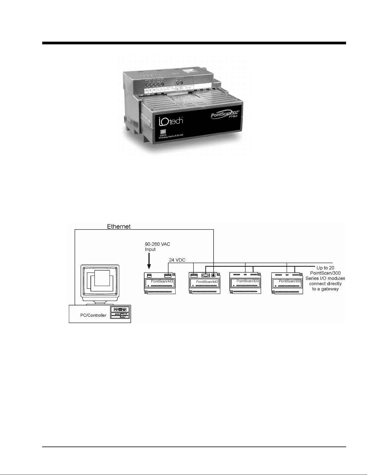
A typical PointScan/300 Series station consists of a DC power supply, a communication gateway, and I/O
modules. The gateway connects to the I/O modules through a daisy-chained "PT-Bus" cable.
(See Section 3.)
Typical PointScan/300 System Configuration
PT-BUS
PointScan/300 User’s Manual
9-26-01
Overview 1-1
Page 8
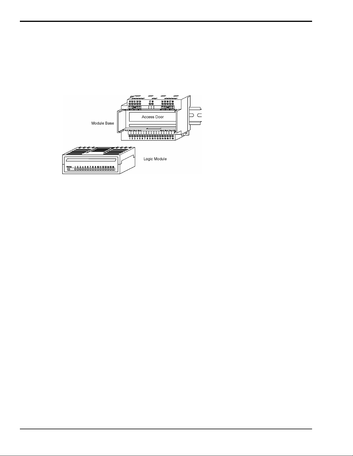
I/O Module Components
A PointScan/300 Series I/O module consists of a base assembly and a removable logic module.
All base assemblies have a hinged door that is accessible when the logic module is removed. In 4-20 mA
analog input modules (PointScan/301, /302, and /304) the hinged door provides access to jumpers and/or
100 ohm replaceable shunts.
A logic module may be removed by lightly squeezing the top and bottom locking tabs and pulling the logic
module straight out. To reinstall, insert the logic module into the base and press firmly until it snaps into
place. The logic module is fully seated when the innermost row of ventilation slots are just covered by the
top surface of the base cover.
I/O Module Assembly
1-2 Overview
9-26-01
PointScan/300 Series Manual
Page 9
Status LED Indication
The “Status” LED on each module may be observed in one of five states:
ON - The module is configured properly and communicating with the gateway.
OFF - There is no power to the module, or the status LED is being turned off intentionally by the I/O Tool
Kit during the module linking operation
LONG BLINK (
has lost communication with the gateway for more than 10 seconds, or the module has not received
configuration data from the gateway. Upon initial system startup (no configuration in the gateway) this
should be the observed LED state on each module.
SHORT BLINK (.
powerup.
WINKING (
module. This winking occurs during module linking procedure. Refer to the online help in the I/O Tool Kit
for more information.
.75 sec. ON, .25 sec. OFF) -
25 sec. ON, .75 sec. OFF) -
10 blinks/ sec.) -
Status LED Wink Feature
The “Status” LED may be intentionally winked (10 blinks/second) by the IO Toolkit program to visually
identify the module when other modules are present.
Isolation
Every PointScan/300 Series I/O module is isolated from ground (1200Vrms @ 1 minute) and additional
isolation is available on select modules (e.g. PointScan/323, 500V channel to channel isolation) for
fault-free operation. Additional levels of isolation are provided with some modules. Refer to the product
specifications in the Remote IO Toolkit online help system for more information.
Long blinking indicates one of two conditions. Either the module
Short blinking indicates a failure of the module self test upon
A status LED may be winked by the I/O Tool Kit utility to bring attention to the
Local Diagnostics
Local diagnostics can be performed through any available port while the gateway is responding to
messages from the other port. Diagnostic software, such as IO Toolkit, can be used to display the status of
the I/O registers.
Hot Swap Feature
I/O modules may be unplugged from their bases, even in live systems. PointScan/300 Series I/O modules
automatically self-configure from system memory. Analog I/O logic modules will automatically upload
and self-adjust to user calibration settings (if any are present) from the module base.
PointScan/300 User’s Manual
9-26-01
Overview 1-3
Page 10

Gateway Memory
All PointScan/442 gateways have nonvolatile (battery-free) memory for storing configuration data from the
I/O Toolkit utility.
Programmable gateways have battery-backed memory for storage of program variables and logged data.
The battery is a rechargeable lithium cell that is kept fresh by the power circuitry in the gateway. The
memory retention period for an unpowered gateway is at least one year at room temperature. The retention
time will be shorter at higher temperatures. The life expectancy of the lithium battery is approximately 10
years.
Calibration
All PointScan/300 Series analog I/O logic modules are factory calibrated over all supported ranges using a
regularly maintained set of standards. Factory calibration data is stored in permanent memory in the logic
module, and cannot be altered. User recalibration may be performed, but is necessary only if inaccuracy in
your field device is observed, or if any of the 100 ohm input shunts are replaced with low tolerance
resistors.
Each analog channel has span and offset calibration settings. Span is the "range" or "gain" of the channel.
Offset is the "zero" setting. Each reported analog I/O value is the product of the factory calibration value
times the user calibration value. The user calibration value is defined as:
(user span value * raw value) + user offset
The user span is a unity value (1) by default. The user offset is zero by default.
Note: All factory and user calibrations are performed in software. There are no adjustment
potentiometers inside the logic modules.
User calibrations are performed using the IO Toolkit utility. Refer to the IO Toolkit on-line help system for
information on calibrating PointScan/300 Series analog I/O.
1-4 Overview
9-26-01
PointScan/300 Series Manual
Page 11

Getting Started With PointScan/300 Series Hardware
Following these steps will make installation and start-up easier.
nMount the Hardware
If you purchased individual PointScan/300 Series components, refer to Section 2 for information on
installation instructions.
oInstall PT-BUS Wiring Between Modules
Make PT-BUS wiring connections between the PointScan/300 Series modules.
Refer to Section 3 for PT-BUS wiring guidelines.
p Connect Power and I/O Wiring to the Modules
Connect AC power to the PointScan/300 Series power supply. Make DC power connections from the
power supply to the gateway and I/O modules (as needed.) Make field wiring connections to the
PointScan/300 Series I/O modules and any peripheral equipment. Refer to the individual module sections
in this manual for connection details.
qInstall Communication Cabling
If you did not purchase a factory communication cable (CA-22), install a RS232 cable between your
computer and serial port on the PointScan/300 Series gateway.
Fabricate and install RS232, RS422 and RS485 cables as needed. If you are using Ethernet gateways,
(PointScan/442) install the correct cabling and peripherals. Refer to the documentation for your Ethernet
communication devices for details.
r Apply Power
Power up the PointScan/300 Series I/O and related peripherals. Observe the status LED on each module.
The normal conditions are as follows:
Module Type
Gateway (PointScan/442) Power and Status LEDs On
I/O modules PointScan/300 Series
in user enclosure
PointScan/443 Power LED on
s Configure Using IO Toolkit
Refer the steps outlined in the online help for each PointScan/300 Series module.
t Test the System
Use the Test I/O window in the IO Toolkit program to verify proper I/O operation in all PointScan/300
Series module.
u Configure Your Computer
Refer to the on-line help in the IO Toolkit for more information.
v Run the (Citec) Software
Refer to the on-line help in the Citec software for more information.
LED, Normal Indication
Status LEDs Blinking
w If You Have Difficulty
If you experience startup trouble, contact IOtech at productsupport@iotech.com.
PointScan/300 User’s Manual
9-26-01
Overview 1-5
Page 12

1-6 Overview
9-26-01
PointScan/300 Series Manual
Page 13
Assembly and Installation 2
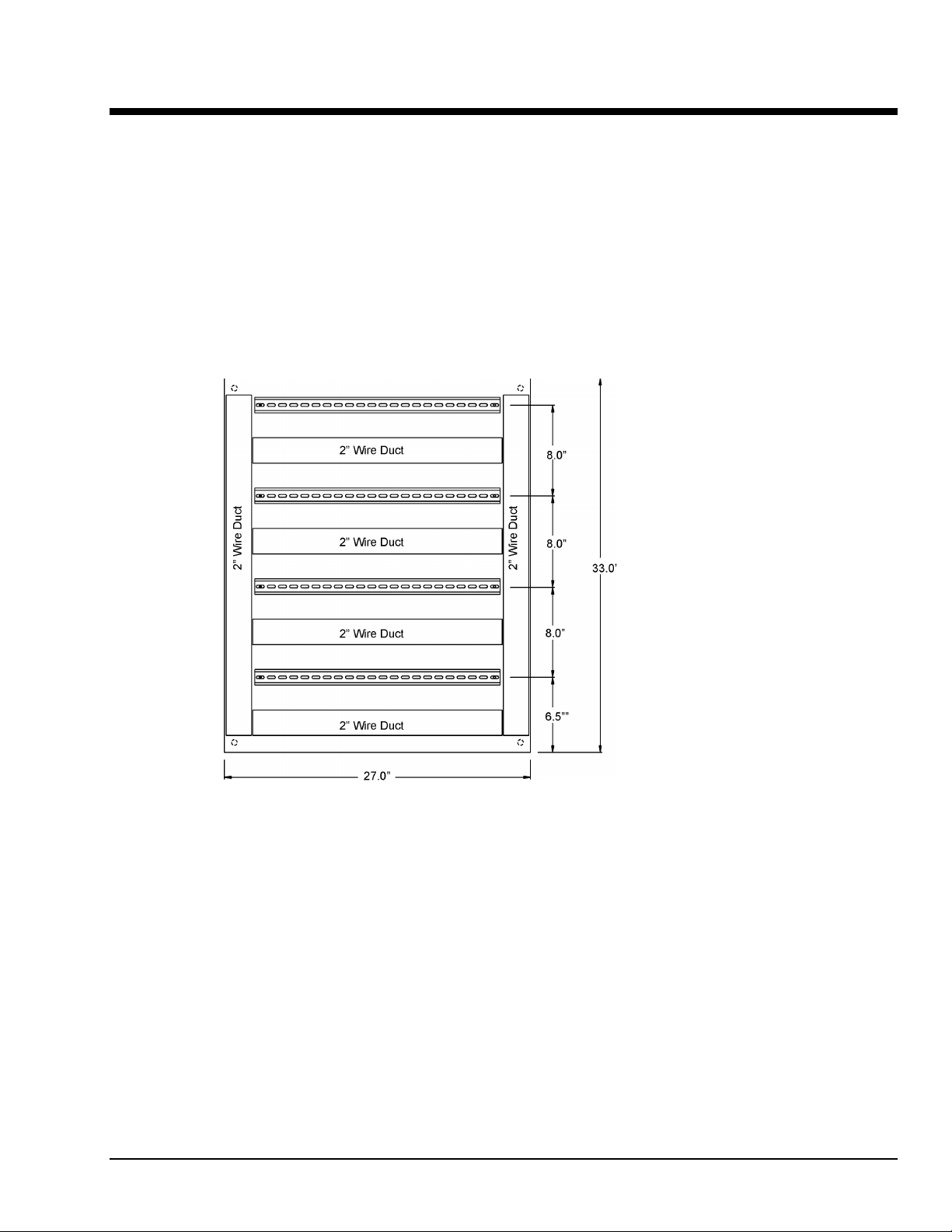
PointScan/300 Series Panel Assembly
PointScan/300 Series I/O snaps onto DIN rail strips fastened to the subpanel. Figure 2-4 shows a sample
panel with DIN rail strips and wire duct attached. Recommended DIN rail spacing is 8 inches. This spacing
allows room for wire duct to be installed without obstructing field wiring installation.
The PointScan/300 Series modules are typically installed against one another, but space may be left
between modules to accommodate other DIN rail mounted components such as terminal blocks and fuse
holders. End clamps are recommended to restrict side-to-side movement. Figures 2-5 through 2-7 show the
physical dimensions of the PointScan/300 Series components.
PointScan/300 Series modules may be installed in any orientation and order on your panel. The modules
are electrically interconnected using PT-Bus wiring, beginning with the gateway. Refer to Section 3 for
more information on PT-Bus wiring.
Sample Layout For a 36” x 30” Enclosure
PointScan/300 User’s Manual 8-23-01 Assembly and Installation 2-1
Page 14

I/O Module and I/O Expander Dimensions
Gateway Dimensions
DIN EN 50022 Suppliers
Manufacturer Type
Altech PR30
Entrelec TS35
Phoenix NS35/7.5
Wago TS35
Weco H-35
Weidmuller TS35
Wieland TS35
2-2 Assembly and Installation
DIN Rail Dimensions
Figure 2-7
8-23-01
PointScan/300 User’s Manual
Page 15

Power and PT-Bus Wiring 3
DC Power Overview
PointScan/300 modules can be powered from the same DC source that is used to power your I/O devices.
No separate power supply is required. Typically, 10 to 30 VDC power is applied to terminals 24 and 25 on
the base of each module.
The PointScan/443 is used to power up to seven PointScan modules of any type, instrumentation loops, and
other devices. It operates on 85-264 VAC (47-63 Hz) or 120-370 VDC and outputs 24 VDC at up to 1 A.
Refer to the figure below for the proper power connections.
DC Power Wiring PointScan/443
PointScan/442 gateways, and user instrumentation loops may be powered from the PointScan/443 power
supply. The PointScan/443 supplies 24 volts DC at a maximum of two amps.
DC Power Wiring (User DC Source)
PointScan/442 gateways, and user instrumentation loops may be powered from a single DC source. The
user DC power source must be between 18 to 30 volts.
Current Requirements
To calculate the current requirements, add the wattage required for the I/O modules in use, then divide the
total wattage by the DC power source voltage. Then add any current needed for user instrumentation loops.
PointScan/300 User’s Manual
9-12-01
Power and PT-Bus Wiring 3-1
Page 16

PT-Bus Wiring Guidelines
PT-Bus wiring connects the PointScan/300 Series I/O modules and expanders to the gateway. Follow the
guidelines for reliable performance.
PT-Bus Capability
Max. modules controlled by one gateway 128
Max. modules connected directly to gateway 20 (any mix)
Required cable type Any with 2 individually
Recommended cables Alpha 2466C, Belden 8723,
Max. cabling off each gateway or expander 50 ft. (16M)
shielded pairs, 22AWG min.
Carol C1352
Connect up to 20 I/O modules directly to the
gateway with a maximum total cabling of 50 feet
(16m).
PT-Bus wiring may be extended into additional cabinets as long as the total length of wire
connected to the gateway or expander stays within the 50 foot limit (16m).
PT-Bus connections may form star configurations
without restrictions.
Use the supplied PT-Bus jumpers between adjacent PointScan components. Otherwise, use the
recommended cable.
3-2 Power and PT-Bus Wiring
9-12-01
PointScan/300 User’s Manual
Page 17

Discrete Input Modules 4
This section documents the following modules:
PointScan/321 PointScan/322 PointScan/323 PointScan/324
PointScan/325 PointScan/326 PointScan/327
8 Channel Input Modules
PointScan/300 eight channel discrete input modules incorporate one of two module base styles. These base
styles and other features are detailed below.
Standard Base
With the standard base, one terminal from each channel is connected to an internal common bus. A single
user power connection to the module allows up to eight input devices to be connected in sourcing or
sinking configurations using two wires each.
Optional Universal Wiring Base
With the optional Universal Wiring base, each discrete input has two independent screw terminals to
provide point to point isolation.
Input Isolation
All discrete inputs are optically isolated from the PointScan/300 series circuitry, regardless of the module
base style. If the optional Universal base is used, the discrete inputs will be channel to channel isolated as
well.
Sinking or Sourcing Wiring
AC inputs should be wired in a sourcing configuration as shown on the next page. All DC input modules
(except the PointScan/325) will read either DC sinking or sourcing wiring. Just reverse the power input
wires (terminals 17 and 18) to configure sinking or sourcing DC wiring.
Counter Feature
All eight channel discrete input modules have an input count accumulator feature. If this feature is enabled
(in the Remote IO Toolkit program), an analog input register will report a unipolar (unsigned) 16-bit count
value that increments on each OFF to ON transition of the corresponding input. The maximum count input
rate is 100 Hz (6000 pulses/min). These accumulations initialize at zero each time power is cycled. They
cannot be reset under software control.
PointScan/300 User’s Manual
8-23-01
Discrete Input Modules 4-1
Page 18

Discrete Input Connections Using the Standard Base
Each Standard Base reduces or eliminates the need for extra screw terminals by internally connecting the
instrumentation power or return wire to each input channel.
For AC applications with inputs on a single AC service:
For most DC applications:
For special inputs from grounded switch closures: (except PointScan/325)
4-2 Discrete Input Modules
8-23-01
PointScan/300 User’s Manual
Page 19

Discrete Input Connections Using The (Optional) Universal Wiring Base
Each (optional) Universal Wiring Base provides channel to channel isolation by supplying two screw
terminals for each input channel. This allows input signals from different power sources to be wired to the
same base.
For AC applications with inputs from different AC sources:
Note: In AC applications, each input may be wired to independent AC sources or line phases.
For DC applications with inputs from different DC sources:
PointScan/300 User’s Manual
8-23-01
Discrete Input Modules 4-3
Page 20

PointScan/322
This high density discrete input module has 16 channels that accept inputs from 10 to 32 volts DC. Connect
your input signals to terminals 1 through 16. Connect the return from your DC power source to terminal 18.
You will need to externally distribute the (+) DC power to your field devices.
High density Input Module
4-4 Discrete Input Modules
8-23-01
PointScan/300 User’s Manual
Page 21

PointScan/327
This high-speed counter module has eight isolated circuits that accept pulse inputs from a variety of
sources, including quadrature and incremental encoders. Count values are reported in 16 bit analog input
registers, with 32 bit results available by cascading two adjacent I/O channels to report total counts. The
states of the counter inputs are also reported as discrete inputs. Pulse rates up to 50 kHz are supported. The
counters may be reset by toggling discrete output bits. Counter modes are selected using the Remote IO
Toolkit program. Refer to the Remote IO Toolkit online help system for more information.
Input Wiring
Screw terminal assignments, compatible only with the universal wiring base, are shown below. For best
noise immunity, connect input signals using twisted wire pairs. To maintain the best differential noise
rejection, do not connect (-) screw terminals together at the I/O base.
High-Speed Counter Module
* Populate the appropriate load resistor, unless your sensor
does not require one.
Typical Wiring Models
PointScan/300 User’s Manual
8-23-01
Discrete Input Modules 4-5
Page 22

4-6 Discrete Input Modules
8-23-01
PointScan/300 User’s Manual
Page 23

Discrete Output Modules 5
This section documents the following modules:
PointScan/336 PointScan/337 PointScan/339
PointScan/340 PointScan/341
8 Channel Output Modules
PointScan/300 Series eight channel discrete output modules incorporate one of two module base styles.
These base styles and other features are detailed below.
Standard Base
With the standard base, one terminal from each channel is connected to an internal common bus. A single
user power connection to the module allows up to eight output devices to be connected in sourcing or
sinking configurations using two wires apiece. This is the most common wiring configuration. Refer to the
next page for sample wiring connections.
(Optional) Universal Wiring Base (-w)
With the (optional) Universal Wiring base, each discrete output has two independent screw terminals to
provide point to point isolation. Sample wiring is shown on the next page.
Output Isolation
All discrete outputs are optically isolated from the PointScan/300 Series circuitry, regardless of the module
base style. If the (optional) Universal base is used, the discrete outputs will be channel to channel isolated
as well.
Watchdog Output Feature
The first DC output channel may be configured (in software) as a watchdog output. If this feature is
selected, the output will be on when there is good command activity from the gateway. The output will no
longer be controlled as a discrete output. The corresponding register will be unused.
PointScan/300 User’s Manual
9-12-01
Discrete Output Modules 5-1
Page 24

Discrete Output Connections Using The Standard Base
Each Standard Base reduces or eliminates the need for extra screw terminals by internally connecting the
instrumentation power or return wire to each output channel.
Sourcing DC outputs:
Sourcing AC outputs:
5-2 Discrete Output Modules
9-12-01
PointScan/300 User’s Manual
Page 25

Discrete Output Connections Using The (optional) Universal Wiring Base
Each (optional) Universal Wiring Base provides channel to channel isolation by supplying two screw
terminals for each output channel. This allows outputs on the same module to be switching different AC or
DC power sources.
For DC applications:
For AC applications:
PointScan/300 User’s Manual
9-12-01
Discrete Output Modules 5-3
Page 26

PointScan/341
This high density discrete output module has 16 channels that source 10 to 32 volts DC to the field devices.
The current rating for each output channel is 1 mA to 500 mA (0.5A). One screw terminal is provided for
the (+) user DC power source.
High density Output Module
High Density Wiring Base
With the standard base, one screw terminal is provided for the output wire to each of the sixteen field
devices. One screw terminal is provided for the user DC power (+). Refer to the figure below for sample
wiring connections. Connect your output wires to terminals 1 through 16. Connect your DC (+) to terminal
18. You will need to externally distribute the DC power return to your field devices.
Watchdog Output Feature
The first DC output channel may be configured (using the Remote IO Toolkit program) as a watchdog
output. If this feature is selected, the output will be on when there is good command activity from the
gateway.
5-4 Discrete Output Modules
9-12-01
PointScan/300 User’s Manual
Page 27

PointScan/336
Dry Contact Relay Module
This discrete output module has six Form C relay output channels that switch DC or AC power to the field
devices. The current rating for each output channel is 0.1 mA to 2 amps DC, or 0.1 mA to 500 mA (0.5A)
AC. Screw terminals, compatible only with the universal wiring base, are provided for the normally closed
and normally open outputs.
Watchdog Output Feature
The first DC output channel may be configured (using the Remote IO Toolkit program) as a watchdog
output. If this feature is selected, the output will be on when there is good command activity from the
gateway.
PointScan/300 User’s Manual
9-12-01
Discrete Output Modules 5-5
Page 28

5-6 Discrete Output Modules
9-12-01
PointScan/300 User’s Manual
Page 29

Analog Input Modules 6
This section documents the following modules:
PointScan/301 PointScan/302 PointScan/303
PointScan/304 PointScan/305 PointScan/306
Power Requirements
The internal analog input circuitry is powered by the gateway through the PT-Bus wiring. External power is
required only for 4-20 mA loop signals coming from an unpowered source.
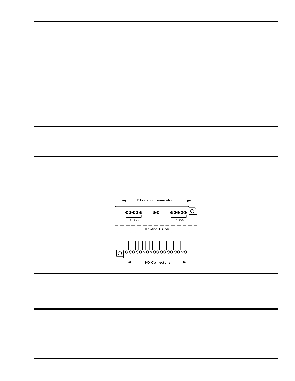
Analog Isolation
The PT-Bus wiring between PointScan/300 Series modules is isolated to a rating of 1,200 volts. Therefore,
all PointScan/300 Series modules are isolated from one another. In addition, the PointScan/304 module
provides 50 volt channel to channel isolation.
4-20 mA Input Circuit Jumpers
The PointScan/304 module has jumpers for connecting or disconnecting 100 ohm current shunts from each
input circuit. The PointScan/301 module has jumpers for providing 24 VDC loop power or instrumentation
ground to each field device. The jumpers are located behind the access door inside the module base. To
gain access to them, unplug the logic module from the base and open the access door. Refer to the
upcoming pages for more information on these jumpers.
These jumpers must be set to match the corresponding input signal type, regardless of software range
selection. Improper jumper selection could result in damage to the input circuitry.
Replaceable Current Shunts
PointScan/300 Series modules that support 4-20 mA inputs have a 100 ohm replaceable shunt for each
channel. These shunts are enabled by jumper settings, and are replaceable if damaged by an equipment
failure or wiring error.
These high precision shunts are located behind the access door inside the analog input module's base. A
spare shunt is provided in the base assembly for your convenience. These shunts are illustrated within the
diagrams of the applicable analog input modules.
If factory supplied shunts are used for replacements, recalibration of the input channels will not be
necessary.
PointScan/300 User’s Manual
9-12-01
Analog Input Modules 6-1
Page 30

PointScan/304
This instrumentation analog input module has eight isolated input channels that accept signals from a wide
variety of field devices. Two screw terminals are provided for each input signal. Note: Compatible only
with the Universal Wiring Base.
Instrumentation Input Module
Thermocouple Burnout Detection
This module has upscale or downscale burnout detection, which is enabled from within the IO Toolkit
program. If the thermocouple resistance exceeds approximately 10 kilohms, the channel reading will be
reported as plus or minus full high temperature or low temperature, depending on whether upscale or
downscale burnout is selected.
Autopolarity Feature (4-20 mA)
If the polarity on a 4-20 mA input is reversed, the value will still be reported properly.
4-20 mA Input Enable Jumpers
This module has a 4-20 mA input enable jumper for each channel. Set each jumper to match the desired
input as shown in the diagram below. The jumper setting must match the range selection in the Remote IO
Toolkit program.
Note: Access these jumpers by removing the plug-in logic module and opening the access door in the
base.
Analog Input Scaling
Thermocouple inputs are automatically linearized and cold junction compensated. Values are reported as
degrees F, degrees C or 0.1 degrees C. Other types of inputs are reported as unscaled values from
-32768 to 32767. Refer to the IO Toolkit online help system for more information.
6-2 Analog Input Modules
9-12-01
PointScan/300 User’s Manual
Page 31

PointScan/301
This 4-20 mA analog input module has eight channels that accept 4-20 mA signals from self powered or
loop powered devices. Two screw terminals are provided for each input channel. The return screw
terminals are tied through movable jumpers to +24 volts DC or to instrumentation ground.
4-20 mA Input Module
Open Loop Detection Feature
The Remote IO Toolkit configuration program provides a selection that allows inputs below
4 mA to be reported as zero, or be reported as negative values to detect loop failure.
Replaceable Current Shunts
This module base has replaceable 100 ohm current shunts, should a faulty field device or wiring error cause
the original shunt to overheat. To access these shunts, unplug the logic module from the base and open the
access door. A spare shunt is provided.
4-20 mA Input Scaling
Current inputs are reported as unscaled values from 0 to 32767. Refer to the Remote IO Toolkit online help
system for more information.
Loop Power Jumpers
If any of your 4-20 mA transmitters require loop power, connect 24 VDC to terminals 17 and 18 of the
module base as shown below. (The 24 VDC may come from an external DC power source, or from the
power supply.) Then set the loop power jumper for each unpowered loop input channel to the DC+
position. For all self-powered 4-20 mA input field devices, set the loop power jumper to the GND position
to provide a ground reference for the input channel.
The loop power jumpers are located inside the module base, and may be accessed by removing the plug-in
logic module and opening the access door.
PointScan/300 User’s Manual
9-12-01
Analog Input Modules 6-3
Page 32

PointScan/302
This high density 4-20 mA analog input module has 16 input channels that accept 4-20 mA signals from a
wide variety of field devices. One screw terminal is provided for the instrumentation ground, and one screw
terminal is provided for each input signal.
High Density Input Module
Open Loop Detection Feature
The IO Toolkit configuration program provides a selection that allows inputs below 4 mA to be reported as
zero, or be reported as negative values to detect loop failure.
Replaceable Current Shunts
This module base has replaceable 100 ohm current shunts, should a faulty field device or wiring error
causes the original shunt to overheat. To access these shunts, unplug the logic module from the base and
open the access door. A spare shunt is provided.
4-20 mA Input Scaling
Current inputs are reported as unscaled values from 0 to 32767. Refer to the IO Toolkit online help system
for more information.
6-4 Analog Input Modules
9-12-01
PointScan/300 User’s Manual
Page 33

PointScan/303
This optional 4-20 mA current limiter module provides overcurrent protection when connected in series
with loop powered 4-20 mA analog devices. One pair of screw terminals is provided for the loop power
source, and one terminal is provided for each of the sixteen protected loops. Refer to the diagram below for
sample wiring connections.
Overcurrent LEDs
A status LED will be lit if the 4-20 mA loop current for that channel exceeds 25 mA.
4-20 mA Loop Current Limiter
PointScan/300 User’s Manual
9-12-01
Analog Input Modules 6-5
Page 34

PointScan/305
This voltage analog input module has eight channels that accept high level voltage signals from a wide
variety of field devices. Two screw terminals are provided for each input channel. The return screw
terminals are bussed internally.
Voltage Input Module
Range Selection
This module supports voltage signals from +/- 1 volt to +/- 10 volts. Range selection is performed using the
IO Toolkit configuration utility. Refer to the IO Toolkit online help system for information on selecting
voltage ranges.
Voltage Input Scaling
Voltage inputs are reported as unscaled values from -32768 to 32767. Refer to the IO Toolkit online help
system for more information.
6-6 Analog Input Modules
9-12-01
PointScan/300 User’s Manual
Page 35

PointScan/306
PointScan/307
Each RTD input module has six channels that accept either 100 ohm platinum RTD inputs (PointScan/306)
or 10 ohm copper RTD inputs (PointScan/307). Three screw terminals, compatible only with the universal
wiring base, are provided for each input channel, to support two, three or four wire RTD connections.
6 RTD Inputs (Platinum)
6 RTD Inputs (Copper)
Pulsed Current Feature
To minimize self heating of the RTD, the measurement current is pulsed on during the measurement period
only.
RTD Linearization
RTD linearization is performed in the gateway firmware. Both American and European linearization
standards are supported, and are selectable in the IO Toolkit program.
RTD Input Scaling
All 100 ohm platinum RTD inputs are reported as unscaled values from -2000 to 8500 (-200 to 850 ºC),
with a resolution of 0.1 degrees C. All 10 ohm copper RTD inputs are reported as unscaled values from 2000 to 2600 (-200 to 260 ºC), with a resolution of 0.1 ºC.
PointScan/300 User’s Manual
9-12-01
Analog Input Modules 6-7
Page 36

6-8 Analog Input Modules
9-12-01
PointScan/300 User’s Manual
Page 37

Analog Output Modules 7
This section documents the following modules:
PointScan/316 PointScan/317 PointScan/318
Analog Output Wiring
PointScan/300 Series analog output modules are supplied with the base. The return screw terminals in this
base are bussed internally. A single user power connection or instrumentation ground connection to the
module allows up to eight output devices to be connected using two wires apiece. Refer to the upcoming
diagrams for sample wiring connections.
PointScan/318
This analog output module has eight channels that provide 5 volt or 10 volt unipolar or bipolar analog output
signals. Two screw terminals are provided for each output channel. The return screw terminals to
instrumentation ground are bussed internally.
Power Requirements
Voltage analog outputs are powered by the analog output module. No external power is required.
8 channel Voltage Output Module
PointScan User’s Manual
8-23-01
Analog Output Modules 7-
1
Page 38

PointScan/317
This analog output module has eight channels that provide 4-20 mA analog output signals. Two screw
terminals are provided for each output channel. The return screw terminals are bussed internally.
8 channel 4-20 mA Outputs
PointScan/316
This analog output module has four channels that provide 4-20 mA analog output signals. Two screw
terminals are provided for each output channel. The return screw terminals are bussed internally.
4 channel 4-20 mA Output Module
Power Requirements
External 24 VDC power is required for 4-20 mA analog outputs.
7-2 Analog Output Modules
8-23-01
PointScan/300 User’s Manual
Page 39

Gateways 8
This section documents the following gateway:
PointScan/442
PointScan/442
Use the PointScan/442 to add either PointScan/300 series I/O or high channel count data loggers
(TempScan/MultiScan/ChartScan) to an Ethernet-based system
Features
• Supports expansion of up to 20 PointScan/300 series modules on a single Ethernet port
• Links serial-based TempScan/1100, MultiScan/1200, or ChartScan/1400 data loggers to Ethernet
• Supports the Modbus/TCP open Ethernet protocol standard
• RS-232 port for diagnostics or modem connection
• DIN-rail or panel mountable
Overview
The PointScan/442 gateway is a convenient solution for linking the economical PointScan/300 series I/O
or the high-channel density TempScan/MultiScan/ ChartScan data loggers to Ethernet via a single IP
address. For applications with small I/O count per node, the PointScan/100 series (with built-in Ethernet) is
an ideal solution, but for applications with higher I/O count per node the PointScan/442 is a practical means
of adding multiple (up to 20) PointScan/300 series I/O. For applications with very high concentrations of
I/O (up to 992) the TempScan/1100, MultiScan/1200, and ChartScan/1400 provide a range of low cost-perchannel options for measuring temperature (TC) and volts (V, mV).
The module’s Ethernet port responds to either Modbus or PT-bus protocol, and module’s RS-232 port is
used for either configuration and diagnostics or as an alter-native means of accessing the I/O. The Ethernet
port and the RS-232 port can be used simultaneously. The PointScan/442 polls the PointScan/300 series
modules or TempScan/MultiScan/ChartScan data loggers and makes data available for display and storage.
Ethernet/RS-232 to PT-bus Gateway
The PointScan/442 gateway works transparently with Citect monitoring, test, and control software but is
fully compatible with Modbus/TCP drivers that are part of most commercially available HMI/SCADA
software.
The PointScan/442 gateway has two communication ports: a serial port, and an Ethernet port.
CA-221
Serial (RS232) Port Cable Wiring
PointScan/300 User’s Manual
9-12-01
Gateways 8-
1
Page 40

8-2 Gateways
9-12-01
PointScan/300 User’s Manual
Page 41

Table PointScan I/O Modules and Accessories A
Definition
Analog Inputs
8 Analog Inputs
(4 to 20 mA)
16 Analog Inputs
(4 to 20 mA)
16 Analog Intputs
(Current Limiters)
8 Universal Analog Inputs
(TC, mA, V, mV)
8 Analog Inputs
(±1, 2, 5 10V)
6 RTD Inputs
(100 Ohm Platinum)
6 RTD Inputs
(10 Ohm Copper)
Combination I/O
8 Analog Inputs &
4 Analog Outputs
(4 to 20 mA)
4 RTD Inputs & 4 Digital Outputs
(100 Ohm Platinum,
12/24 VDC/VAC)
Analog Outputs
4 Analog Outputs
(4 to 20 mA)
8 Analog Outputs
(4 to 20 mA)
8 Analog Outputs
(±5V, ±10V, 0 to 5V, 0 to 10V)
Digital Inputs
8 Digital Inputs
(12/24 VDC/VAC)
16 Digital Inputs
(12/24 VDC/VAC)
8 Digital Inputs
(5 VDC)
8 Digital Inputs
(48 VDC/VAC)
8 Digital Inputs
(120 VDC/VAC)
8 Digital Inputs
(240 VAC)
8 HS Counters with Encoders
(32-bit, 4 to 30V)
Combination I/O
4 Digial Inputs & Outputs
(12/24 VDC)
8 Digial Inputs & Outputs
(12/24 VDC)
Distributed I/O Modules
Ethernet RS-485 PT-Bus
— PointScan/201 PointScan/301
PointScan/102 PointScan/202 PointScan/302
— — PointScan/303
PointScan/104 PointScan/204 PointScan/304
— — PointScan/305
— — PointScan/306
— — PointScan/307
PointScan/108 — —
PointScan/109 — —
— PointScan/216 PointScan/316 Provides 4 to 20 mA outputs with 13-bit resolution
— PointScan/217 PointScan/317 Provides 4 to 20 mA outputs with 13-bit resolution
— — PointScan/318 Provides voltage outputs with 14-bit resolution
— PointScan/221 PointScan/321
PointScan/122 PointScan/222 PointScan/322
— — PointScan/323
— — PointScan/324
— — PointScan/325
— — PointScan/326
PointScan/127 — PointScan/327
— PointScan/228 —
PointScan/129 — —
Measure analog current with 14-bit resolution
Measure analog current with 14-bit resolution
Provides short circuit protection for 4 to 20 mA inputs
Measure TCs (J, K, E, R, T, B, C, N, S), floating 4 to 20
mA, or mV, V with 16-bit resolution
Measure voltage inputs with 12-bit resolution
Measure 100 Ohm platinum RTDs (2, 3, or 4 wire) with
16-bit resolution
Measure 10 Ohm copper RTDs (2 or 3 wire) with 16-bit
resolution
Provides 4 to 20 mA inputs and outputs with 16-bit
resolution
Measure 100 Ohm platinum RTDs (2, 3, or 4 wire) and
digital inputs
Read digital (ON/OFF) inputs
Read digital (ON/OFF) inputs
Read digital (ON/OFF) inputs
Read digital (ON/OFF) inputs
Read digital (ON/OFF) inputs
Read digital (ON/OFF) inputs
Count rates up to 50-kHz plus quadrature encoder
Read digital (ON/OFF) inputs, switch digital (ON/OFF)
outputs
Read digital (ON/OFF) inputs, switch digital (ON/OFF)
outputs
Description
8 Digital Inputs & 8 Analog Inputs
(12/24 VDC/VAC, 4 to 20 mA)
4 Digital Inputs & 4 Analog Inputs
(12/24 VDC/VAC, 4 to 20 mA)
PointScan/300 User’s Manual
PointScan/130 — —
— PointScan/231 —
9-12-01
Read digital (ON/OFF) inputs, output 4 to 20 mA with
16-bit resolution
Read digital (ON/OFF) inputs, output 4 to 20 mA with
16-bit resolution
Table PointScan I/O Modules and Accessories A-1
Page 42

Digital Outputs
6 Relay Outputs
(120 VDC/VAC, 2A max)
8 Digital Outputs
(0 to 60 VDC, 2A max)
8 Digital Outputs
(60 to 150 VDC, 1A max)
8 Digital Outputs
(16 to 140 VAC, 2A max)
8 Digital Outputs
(140 to 265 VAC, 2A max)
16 Digital Outputs
(10 to 32 VDC, 0.5A max)
16 Digital Outputs
(10 to 30 VDC, 1A max)
8 Digital Outputs
(10 to 30 VDC, 3A max)
— — PointScan/336
— — PointScan/337
— — PointScan/338
— — PointScan/339
— — PointScan/340
— — PointScan/341
PointScan/142 PointScan/242 —
— PointScan/243 —
Dry contact relay outputs, SPDT (FormC)
High-current control outputs with isolation
High-current control outputs with isolation
High-current control outputs with isolation
High-current control outputs with isolation
Low-current outputs to drive low power devices
High-current control outputs with isolation
High-current control outputs with isolation
Accessories
Field Configuration Module PointScan/440
RS-232/RS-485 Converter PointScan/441
Ethernet/RS-232 to PT-bus Gateway PointScan/442
Power Supply (24 VDC @ 1A) PointScan/443
A-2 Table PointScan I/O Modules and Accessories
9-12-01
PointScan/300 User’s Manual
 Loading...