

Page 1

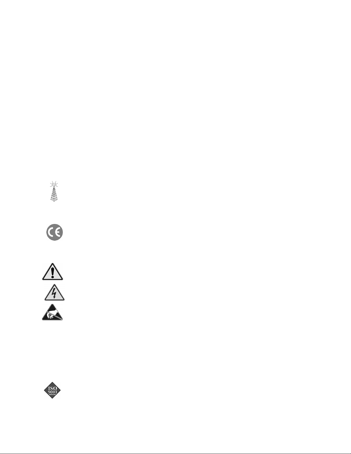
PointScan/200 Series
User’s Manual
RS485 Distributed I/O
the smart approach to instrumentation
™
IOtech, Inc.
25971 Cannon Road
Cleveland, OH 44146-1833
Phone: (440) 439-4091
Fax: (440) 439-4093
E-mail (sales): sales@iotech.com
E-mail (post-sales): productsupport@iotech.com
Internet: www.iotech.com
PointScan/200 Series
User’s Manual
RS 485 Distributed I/O
p/n
1085-0902
Rev.
1.0
© 2001 by IOtech, Inc. September 2001 Printed in the United States of America
Page 2

Page 3
Warranty Information
Your IOtech warranty is as stated on the product warranty card. You may contact IOtech by phone,
fax machine, or e-mail in regard to warranty-related issues.
Phone: (440) 439-4091, fax: (440) 439-4093, e-mail: sales@iotech.com
Limitation of Liability
IOtech, Inc. cannot be held liable for any damages resulting from the use or misuse of this product.
Copyright, Trademark, and Licensing Notice
All IOtech documentation, software, and hardware are copyright with all rights reserved. No part of this product may be
copied, reproduced or transmitted by any mechanical, photographic, electronic, or other method without IOtech’s prior written
consent. IOtech product names are trademarked; other product names, as applicable, are trademarks of their respective
holders. All supplied IOtech software (including miscellaneous support files, drivers, and sample programs) may only be used
on one installation. You may make archival backup copies.
FCC Statement
IOtech devices emit radio frequency energy in levels compliant with Federal Communications Commission rules (Part 15)
for Class A devices. If necessary, refer to the FCC booklet How To Identify and Resolve Radio-TV Interference Problems
(stock # 004-000-00345-4) which is available from the U.S. Government Printing Office, Washington, D.C. 20402.
CE Notice
Many IOtech products carry the CE marker indicating they comply with the safety and emissions standards of the
European Community. As applicable, we ship these products with a Declaration of Conformity stating which
specifications and operating conditions apply.
Warnings, Cautions, Notes, and Tips
Refer all service to qualified personnel. This caution symbol warns of possible personal injury or equipment damage
under noted conditions. Follow all safety standards of professional practice and the recommendations in this manual.
Using this equipment in ways other than described in this manual can present serious safety hazards or cause equipment
damage.
This warning symbol is used in this manual or on the equipment to warn of possible injury or death from electrical
shock under noted conditions.
This ESD caution symbol urges proper handling of equipment or components sensitive to damage from electrostatic
discharge. Proper handling guidelines include the use of grounded anti-static mats and wrist straps, ESD-protective
bags and cartons, and related procedures.
Specifications and Calibration
Specifications are subject to change without notice. Significant changes will be addressed in an addendum or revision to the
manual. As applicable, IOtech calibrates its hardware to published specifications. Periodic hardware calibration is not
covered under the warranty and must be performed by qualified personnel as specified in this manual. Improper calibration
procedures may void the warranty.
Quality Notice
IOtech has maintained ISO 9001 certification since 1996. Prior to shipment, we thoroughly test our products and
review our documentation to assure the highest quality in all aspects. In a spirit of continuous improvement, IOtech
welcomes your suggestions.
Page 4

INSTALLATION AND HAZARDOUS AREA WARNINGS
These products should not be used to replace proper safety interlocking. No software-based device (or any
other solid-state device) should ever be designed to be responsible for the maintenance of consequential
equipment or personnel safety. In particular, IOtech disclaims any responsibility for damages, either direct
or consequential, that result from the use of this equipment in any application.
All power, input and output (I/O) wiring must be in accordance with Class I, Division 2 wiring methods and
in accordance with the authority having jurisdiction.
WARNING – EXPLOSION HAZARD – SUBSTITUTION OF COMPONENTS MAY IMPAIR
SUITABILITY FOR CLASS 1, DIVISION 2.
WARNING – EXPLOSION HAZARD – WHEN IN HAZARDOUS LOCATIONS, DISCONNECT
POWER BEFORE REPLACING OR WIRING MODULES.
WARNING – EXPLOSION HAZARD – DO NOT DISCONNECT EQUIPMENT UNLESS POWER HAS
BEEN SWITCHED OFF OR THE AREA IS KNOWN TO BE NONHAZARDOUS.
Note: Refer to the IO Toolkit software’s online help for detailed product specifications and
configuration settings.
Page 5

Table of Contents
1 - General Information
Overview …… 1-1
General Specifications …… 1-1
I/O Module Components …… 1-2
DC Power Overview …… 1-2
DC Power Wiring PointScan/443 …… 1-3
DC Power Wiring (User Source) …… 1-3
Current Requirements …… 1-3
PointScan/200 LEDs …… 1-3
I/O Module Status LED …… 1-3
Status LED Wink Feature ……1-3
Isolation ……1-4
Local Diagnostics …… 1-4
Hot Swap Feature …… 1-4
Calibration …… 1-5
Getting Started …… 1-6
n
Mount the Hardware …… 1-6
o
Install Ethernet/RS485 Wiring Between
Modules …… 1-6
p
Connect Power and I/O Wiring to the
Modules …… 1-6
q
Install Communication Cabling …… 1-6
r
Apply Power …… 1-6
s
Configure Using IO Toolkit …… 1-6
t
Test the System …… 1-6
u
Configure Your Computer …… 1-6
v
Run the Software
w
If You Have Difficulty …… 1-6
2 - RS485 Wiring Guidelines
RS485 Wiring Guidelines …… 2-1
PointScan/441 RS232 to RS485 Four Port
Connector …… 2-1
Overview …… 2-1
RS232 Wiring …… 2-1
RS485 Wiring …… 2-1
Screw Torque …… 2-2
PointScan/200 Series Panel Assembly …… 2-3
Dimension Drawings …… 2-4
3 - Configuration Tools
PointScan/440
Configuration Tool
Operation …… 3-1
Wiring …… 3-1
RS232 Mode …… 3-1
Alternative Setup Method …… 3-1
IO Toolkit …… 3-1
Portable Remote I/O Field
…… 3-1
4 - Discrete Input Modules
PointScan/221
with Direct Field Wiring Base
PointScan/221
with Isolated Inputs
Overview …… 4-1
Standard Wiring …… 4-1
Optional Wiring …… 4-1
I/O Registers …… 4-1
PointScan/222
Module
…… 4-3
Overview …… 4-3
Wiring …… 4-3
I/O Registers …… 4-3
8 Discrete Inputs / Counters
8 Discrete Inputs / Counters
…… 4-1
High Density Discrete Input
5 - Discrete Output Modules
PointScan/243
Module
……
Overview …… 5-1
Wiring …… 5-1
I/O Registers …… 5-1
TPO Feature …… 5-1
PointScan/242
Module
……
Overview …… 5-2
Wiring …… 5-2
I/O Registers …… 5-2
8 Channel High Output Current
5-1
High Density Discrete Output
5-2
6 - Analog Input Modules
PointScan/201
……
Inputs
Overview …… 6-1
Wiring …… 6-1
Current Shunts …… 6-1
I/O Registers …… 6-1
PointScan/202
Input Module
Overview …… 6-2
Wiring …… 6-2
Current Shunts …… 6-2
I/O Registers …… 6-2
PointScan/204
Module
…… 6-3
Overview …… 6-3
Wiring …… 6-3
Current Shunts …… 6-3
I/O Registers …… 6-3
8 Channel 4-20 mA Analog
6-1
High Density 4-20 mA Analog
……6-2
Instrumentation Analog Input
…… 4-1
PointScan/200 User’s Manual
9-25-01
5
Page 6

7 - Analog Output Modules
PointScan/217
Output Module
PointScan/216
Output Module
Overview …… 7-1 Wiring …… 7-1 I/O Registers …… 7-1
8 Channel 4-20 mA Analog
…… 7-1
4 Channel 4-20 mA Analog
…… 7-1
8 - Combination I/O Modules
PointScan/228
Output Module
Overview …… 8-1
Wiring …… 8-1
I/O Registers …… 8-2
PointScan/231
Analog Input Module
Overview …… 8-2
Wiring …… 8-3
Current Shunts …… 8-3
I/O Registers …… 8-3
Combined Discrete Input and
…… 8-1
Combined Discrete Input and
…… 8-2
Appendix A – Table of PointScan I/O
Modules and Accessories
vi Analog Output Modules
9-25-01
PointScan/200 User’s Manual
Page 7
General Information 1
Overview
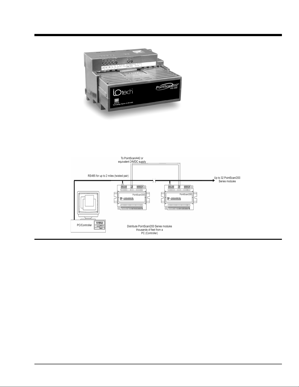
This manual will help you install and maintain PointScan/200. In summary, wiring for power,
communications and I/O is connected to each module’s base. Then, setup choices are entered using the
IO Toolkit and the system is ready to run.
General Specifications
These general specifications apply to all PointScan/200 modules.
Supply Voltage 9 - 30 VDC, 0.5 Watt typical per module
Modules per RS485 bus 32 (use a PointScan/441 to drive a total of 128 modules)
RS485 Isolation 1200 Volts RMS (for 1 minute)
Operating Temperature
Storage Temperature
Humidity 5 to 95% (non-condensing)
PointScan/200 User’s Manual
(25 mA @ 24 VDC – varies by module and load).
-30 to 70 °C
-40 to 85 °C
9-25-01
General Information 1-1
Page 8
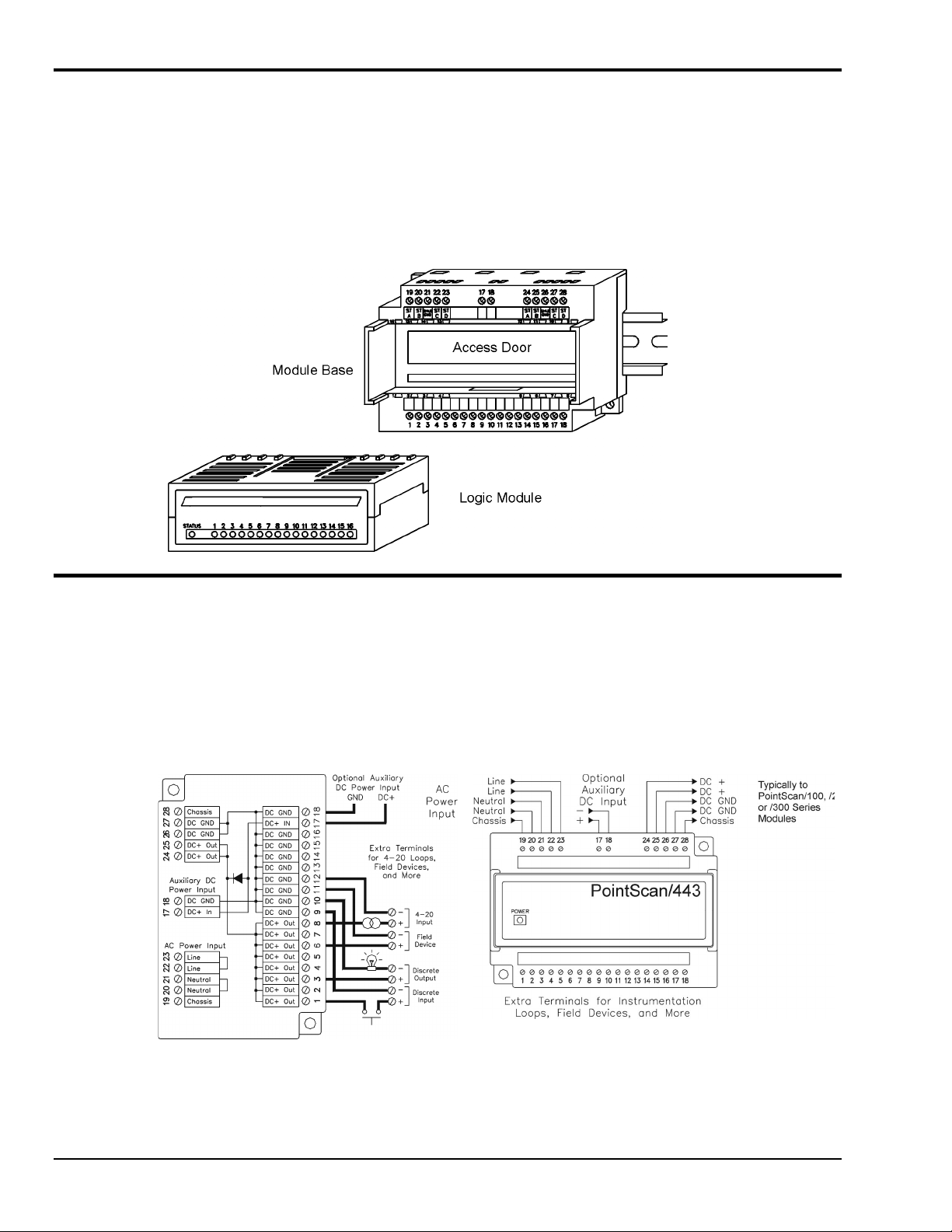
I/O Module Components
A PointScan/200 Series I/O module consists of a base assembly and a removable logic module. All base
assemblies have a hinged door that is accessible when the logic module is removed. In 4-20 mA analog
input modules (PointScan/201, /202, /204, and /231) the hinged door provides access to jumpers and/or 100
ohm replaceable shunts.
A logic module may be removed by lightly squeezing the top and bottom locking tabs and pulling the logic
module straight out. To reinstall, insert the logic module into the base and press firmly until it snaps into
place. The logic module is fully seated when the innermost row of ventilation slots are just covered by the
top surface of the base cover.
DC Power Overview
PointScan/200 modules can be powered from the same DC source that is used to power your I/O devices.
No separate power supply is required. Typically, 10 to 30 VDC power is applied to terminals 17 and 18 on
the base of each module. Some PointScan/200 Series modules distribute power or return connections to
I/O terminals for your convenience in making field-wiring connections. Refer to the wiring diagram for
each module for more information.
The PointScan/443 is used to power up to seven PointScan modules of any type, instrumentation loops, and
other devices. It operates on 85-264 VAC (47-63 Hz) or 120-370 VDC and outputs 24 VDC at up to 1 A.
Refer to the figure below for the proper power connections.
1-2 General Information
9-25-01
PointScan/200 User’s Manual
Page 9

DC Power Wiring PointScan/443
PointScan/442 gateways, and user instrumentation loops may be powered from the PointScan/443 power
supply. The PointScan/443 supplies 24 volts DC at a maximum of two amps.
DC Power Wiring (User DC Source)
PointScan/442 gateways, and user instrumentation loops may be powered from a single DC source. The
user DC power source must be between 18 to 30 volts.
Current Requirements
To calculate the current requirements, add the wattage required for the PointScan/200 Series modules in
use, then divide the total wattage by the DC power source voltage. Then add any current needed for user
instrumentation loops.
PointScan/200 LEDs
Every PointScan/200 module has a number of LEDs. These LEDs can be useful for system diagnostics.
These LEDs can be observed in the following states:
I/O Module Status LED
On, with a quick “OFF” BLINK [Long Blink](1.9 seconds ON, .1 seconds OFF) - The module is
configured and fully operational, but has not received a valid request from the host for a time longer than
the specified time out period. A communication time out has occurred.
Full ON [On] - The module is configured, fully operational, and has received communication from the host
device before the timeout period expired. This is the desired LED indication during system operation.
HALF BLINK [Long Blink] (1 second ON, 1 second OFF) - The module is not adequately configured and
requires a download from the IO Toolkit program.
Full OFF [Off] - There is no power to the module, or the status LED is being turned off intentionally by
the IO Toolkit during the module loading operation.
Off, with a quick “ON” BLINK [Short Blink] (1.9 seconds OFF, .1 seconds ON ) - The module failed
self-test at initialization. It will not attempt communication and should be replaced.
Status LED Wink Feature
The “Status” LED may be intentionally winked (10 blinks/second) by the IO Toolkit program to visually
identify the module when other modules are present.
PointScan/200 User’s Manual
9-25-01
General Information 1-3
Page 10
Isolation
Every PointScan/200 Series I/O module is isolated from ground (1200 Vrms 1 minute) and additional
modules for fault-free operation. Additional levels of isolation (e.g. 500V channel to channel isolation)are
provided with some modules. Refer to the product specifications in the IO Toolkit online help system for
more information.
Local Diagnostics
Local diagnostics can be performed through any available port while the gateway is responding to
messages from the other port. Diagnostic software, such as IO Toolkit, can be used to display the status of
the I/O registers.
Hot Swap Feature
I/O modules may be unplugged from their bases, even in live systems. PointScan/100 Series I/O modules
automatically self-configure from system memory. Analog I/O logic modules will automatically upload
and self-adjust to user calibration settings (if any are present) from the module base.
1-4 General Information
9-25-01
PointScan/200 User’s Manual
Page 11

Calibration
All PointScan/200 Series analog I/O logic modules are factory calibrated over all supported ranges using a
regularly maintained set of standards. Factory calibration data is stored in permanent memory in the logic
module, and cannot be altered. User recalibration may be performed, but is necessary only if inaccuracy in
your field device is observed, or if any of the 100 ohm input shunts are replaced with low tolerance
resistors.
Each analog channel has span and offset calibration settings. Span is the "range" or "gain" of the channel.
Offset is the "zero" setting. Each reported analog I/O value is the product of the factory calibration value
times the user calibration value. The user calibration value is defined as:
(user span value * raw value) + user offset
The user span is a unity value (1) by default. The user offset is zero by default.
Note: All factory and user calibrations are performed in software. There are no adjustment
potentiometers inside the logic modules.
User calibrations are performed using the Remote IO Toolkit utility. Refer to the Remote IO Toolkit online help system for information on calibrating PointScan/200 Series analog I/O.
Communicating with PointScan/200
Protocols supported Modbus, ASCII/RTU, and proprietary
Wiring configuration RS485 two-wire partyline
RS485 isolation (module to module) 1200 Volts RMS 1 minute
Supported baud rates 2400, 4800, 9600, 14400, 19200, 38400, 57600 baud
Factory communications settings 9600 baud, no parity, 8 data bits
Cable recommendation Shielded, twisted pair with drain wire desirable. Data rated
cable is recommended for greater distances.
Limitations: cable up to 1 km 24 AWG and 57,600 baud
cable up to 2 km 20 AWG and 38,400 baud
cable up to 3.5 km 18 AWG and 19,200 baud
Number of modules on one RS485 port 32 maximum
Number of addressable modules 128 with PointScan/441
PointScan/200 User’s Manual
9-25-01
General Information 1-5
Page 12

Getting Started
Following these steps will make installation and start-up easier.
nMount the Hardware
Refer to Section 2 for installation instructions for PointScan series I/O and optional accessories
oInstall Ethernet/ RS485 Wiring Between Modules
Make PT-Bus (PointScan/300) or RS485 (PointScan/200) wiring connections the modules.
Refer to Section 2 for wiring guidelines.
pConnect Power and I/O Wiring to the Modules
Connect AC power to the PointScan/442 power supply. Make DC power connections from the power
supply to the I/O modules and optional accessories (as needed.) Make field wiring connections to the
PointScan/100 Series I/O modules and any peripheral equipment.
Refer to the individual module sections in this manual for connection details.
qInstall Communication Cabling
For PointScan/100 Series modules connect the Ethernet Cable (RJ45) to the resident connector.
For PointScan/200 Series modules connect the Twisted Pair (RS485) cabling.
Refer to Chapter 2 for wiring details.
r Apply Power
Power up the PointScan/100 Series I/O and related peripherals. Observe the status LED on each module.
The normal conditions are as follows:
Module Type LED, Normal Indication
PointScan/442 Power Supply Power LED On
PointScan/200 Series Status LEDs Blinking
s Configure Using IO Toolkit
Refer to the steps outlined in the online help for each PointScan/200 Series module.
t Test the System
Refer to chapter 3, IO Toolkit and use the Test I/O window in the IO Toolkit program to verify proper I/O
operation in all PointScan/200 Series module.
u Configure Your Computer
Refer to the on-line help in the IO Tool Kit for more information.
v Run the (Citec) Software
Refer to the on-line help in the Citec software for more information.
w If You Have Difficulty
If you experience startup trouble, contact IOtech at productsupport@iotech.com.
1-6 General Information
9-25-01
PointScan/200 User’s Manual
Page 13

RS485 Wiring Guidelines 2
RS485 Wiring Guidelines
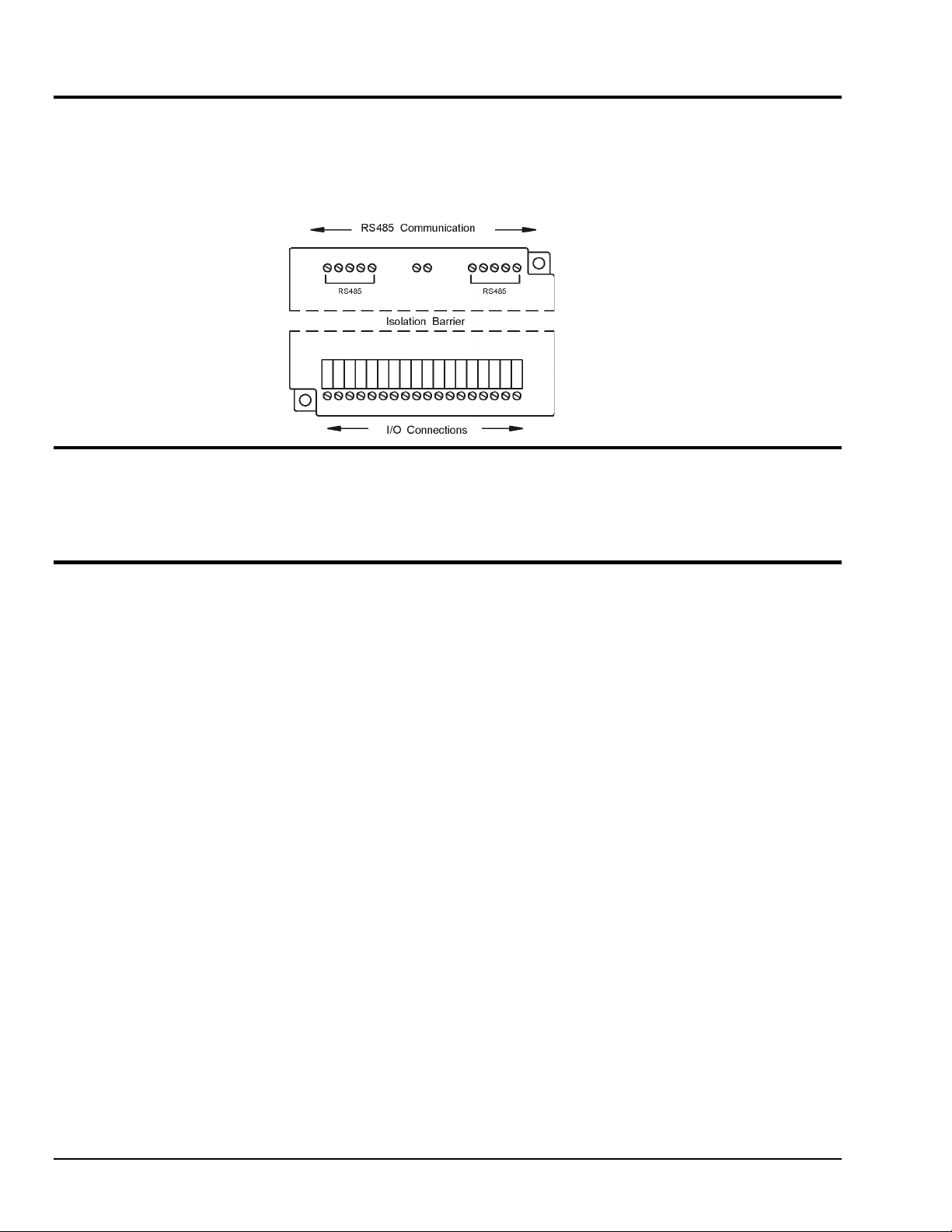
PointScan/200 modules communicate with a master controller (PC) using a two wire RS485 party-line. It
is recommended that in addition to the two signal wires, a shield or ground wire be connected to reference
all stations to a common return. The RS485 port on all PointScan/200 modules is isolated from its internal
circuitry, local power source, and I/O wiring to improve communications reliability. It is recommended that
only 32 PointScan/200 modules be connected on an unbuffered RS485 party-line, and that the termination
jumper be installed on the last module on the end of a network segment. Limiting the cabling to two
network arms (segments) radiating from the master controller will yield best signal results.
PointScan/441
Overview
This interface provides a convenient way to connect RS485 PointScan/200 bussed Series I/O modules to a
RS232 port on a master controller (DC). Designed specifically for driving modules this converter is fully
automatic, requiring no user settings. Four RS485 ports are provided to allow up to 128 I/O modules to be
connected in a star configuration (multiple network arms). Electrical isolation is provided between the
RS232 and RS485 ports for increased reliability.
This RS232 to RS485 converter is recommended when:
1. I/O modules need to be connected to an RS232 port on the master controller
2. More than 32 modules and/or other RS485 devices are to be addressed.
3. A “star” wiring configuration (more than two network wiring segments) is needed.
4. Electrical isolation between the RS485 party-line and the RS232 port on the master controller will
RS232 Wiring
Only the transmit (TD), receive (RD) and common return (GND) signals need be connected in the RS232
cable. A standard suitable null modem cable may be connected to the DB9 connector in the face of the
module. Alternatively, signals may be connected to the wiring base as shown in the upcoming diagram. The
PointScan/441 module detects message direction and automatically generates a transmitter enable (keying)
signal. The DTR signal is always high (asserted) to provide a pull up for any lines in the master controller
that may need to be tied off.
RS232 to RS485 Four Port Converter
increase reliability.
RS485 Wiring
All four RS485 ports are interchangeable and may each drive up to 32 PointScan/200 modules. In addition
to the two wire signal pair, it is recommended that a shield or third ground conductor be connected to the
RS485 ground terminal to reference all stations together. All four RS485 ports are referenced to the same
internal signal common (ground), which is electrically isolated from the RS232 port and DC power input
terminals. It is recommended that a jumper wire be connected between the “RS485(-)” terminal and
“Term” terminal if this device is on the end of a network arm (i.e. it is the last station on the RS485 bus).
PointScan/200 User’s Manual
9-12-01
RS485 Wiring Guidelines 2-1
Page 14

Screw Torque
All the screw terminals on the base should be tightened to a maximum of 3.48 in-lbs.
2-2 RS485 Wiring Guidelines
9-12-01
PointScan/200 User’s Manual
Page 15

PointScan/200 Series Panel Assembly
PointScan/200 Series I/O snaps onto DIN rail strips fastened to the subpanel. The following figure shows
a sample panel with DIN rail strips and wire duct attached. Recommended DIN rail spacing is 8 inches.
This spacing allows room for wire duct to be installed without obstructing field wiring installation.
The PointScan/200 Series modules are typically installed against one another, but space may be left
between modules to accommodate other DIN rail mounted components such as terminal blocks and fuse
holders. End clamps are recommended to restrict side-to-side movement. The next figures show the
physical dimensions of the PointScan/200 Series components.
PointScan/200 Series modules may be installed in any orientation and order on your panel. The modules
are electrically interconnected using RS485 wiring, beginning with the gateway.
PointScan/200 User’s Manual
Sample Layout For a 36” x 30” Enclosure
9-12-01
RS485 Wiring Guidelines 2-3
Page 16

PointScan/100, PointScan/200, PointScan/300 Series I/O modules,
PointScan/441 (RS-232/RS-485 Converter), and PointScan/443 (Power Supply) Dimmensions
Gateway Dimensions
DIN EN 50022 Suppliers
Manufacturer Type
Altech PR30
Entrelec TS35
Phoenix NS35/7.5
Wago TS35
Weco H-35
Weidmuller TS35
Wieland TS35
2-4 RS485 Wiring Guidelines
DIN Rail Dimensions
9-12-01
PointScan/200 User’s Manual
Page 17

Configuration Tools 3
PointScan/440
Operation
This setup tool is the most convenient way to configure a PointScan/200 module. Unplug any module and
insert this setup tool in its place. Commands from the IO Toolkit in your Windows-based PC store the
configuration information into permanent memory in the module’s base. This module automatically reads
the unique serial number stored in the base, making it unnecessary for you to enter the serial number into
the software manually. Upon reinsertion, the I/O module finds this configuration information, instantly
configures itself and begins to scan I/O. It is permissible to configure PointScan/200 modules in live
systems using this setup tool.
Note: PointScan/200 “smart bases” allow hot swap of live modules -- an exclusive IOtech feature.
Wiring
Connect this module to your Windows PC using a standard Serial (RS232) cable. Only the transmit (TD),
receive (RD) and common return (GND) signals are actively used. The RS232 port on this configuration
tool is electrically isolated to protect your computer in the event of field wiring errors. This module
requires DC supply power on terminals 17 and 18 on the wiring base it is plugged into. No other
connections are required. (I/O wiring will be left undisturbed.)
RS232 Mode
This module always communicates to the host PC at 9600 baud, with no parity and eight data bits. Be sure
to set the communications port on your computer to these default settings.
Portable Remote I/O Field Configuration Tool
Alternative Setup Method
PointScan/200 modules may also be configured by connecting the RS485 party-line to an RS485 port or
RS232 port (through a converter) on your PC. It will be necessary to enter the serial number found on each
module’s base in the IO Toolkit to enable this setup software to initially talk to each module. In most
situations, setup through the RS485 port can only be done with the system off-line. Use a PointScan/440
module for on-line setup changes. (See above.)
IO Toolkit
All configuration parameters are entered using the IO Toolkit Windows software, which stores all setup
information into permanent memory in each module’s wiring base. No field jumpers or DIP switches are
required on PointScan/200 module (except wiring jumpers in the base of some 4 - 20 mA input modules).
PointScan/200 User’s Manual
9-12-01
Configuration Tools 3-1
Page 18

3-2 Configuration Tools
9-12-01
PointScan/200 User’s Manual
Page 19

Discrete Input Modules 4
PointScan/221 PointScan/221
Overview
The standard field wired base provides a pre-wired connection to DC power for each of the eight discrete
input channels. For applications which require individually isolated, ground sinking,
or AC inputs, the optional universal wiring base is recommended. An input count feature uses analog input
registers to accumulate the positive transitions of each input. More information on this and other features
can be found in the on-line help supplied with the IO Toolkit.
Number of Channels 8 discrete inputs with pulse counter feature
Input Voltage Range 10 - 30 VDC (standard), 10 - 30 VDC/VAC (optional)
Maximum Count Rate 100 Hz (6000 / minute) each input, plus selectable 2KHz (120,000 / minute)
Standard Wiring
The even numbered terminals (2 - 16) on this field wiring ready base are pre-wired to the DC power (+)
terminal. Adjacent pairs of terminals are connected to each input (switch) device.
Optional Wiring
A pair of floating terminals is provided for each input to provide channel-to-channel isolation
(floating inputs) and a choice of sourcing (power switching), sinking (ground switching) or AC signals on
each input.
8 Discrete Inputs / Counters with Direct Field Wiring Base
8 Discrete Inputs / Counters with Isolated Inputs
mode for input 1 only
I/O Registers
Function IOtech Registers Modbus Registers
Discrete Inputs X0 - X7 10001 – 10008
Counter Inputs AX0 - AX7 30001 - 30008 Unsigned values: 0 Æ 65,535
PointScan/200 User’s Manual
9-12-01
Discrete Output Modules 4-1
Page 20

4-2 Discrete Output Modules
9-12-01
PointScan/200 User’s Manual
Page 21

PointScan/222
Overview
Sixteen discrete inputs accept DC sourcing signals that are all tied to a common return. More information
can be found in the on-line help supplied with the IO Toolkit.
Number of Channels 16 discrete inputs (connected to a common DC source)
Input Voltage Range 10 - 30 VDC
Input Current @ 12 VDC 3.5 mA
Input Current @ 24 VDC 7.0 mA
Wiring
This high density input module provides a single terminal input for each channel. Positive DC voltage must
be applied to an input to indicate an ON condition. All channels are referenced to a common return which
is connected to the negative side (ground) of the DC power source.
I/O Registers
Function IOtech Registers Modbus Registers
Discrete Inputs X0 - X15 10001 – 10016
High Density Discrete Input Module
PointScan/200 User’s Manual
9-12-01
Discrete Output Modules 4-3
Page 22

4-4 Discrete Output Modules
9-12-01
PointScan/200 User’s Manual
Page 23

Discrete Output Modules 5
PointScan/243
Overview
Eight discrete output channels provide up to 3 Amps DC to motor contactors, valves, and other loads.
Overload and thermal shutdown protection are provided. Each of the eight outputs may optionally be
configured as Time Proportioned Outputs that pulse ON at a duty cycle proportional to an analog output
register value. Typically these TPO outputs are controlled by a PID loop or other process algorithm in a
control program. More information may be found in the on-line help supplied with the IO Toolkit.
Number of Channels 8 discrete outputs connected to a common DC source
Output Voltage Range 10 - 30 VDC
Max. Load per Output 3 Amps
Max. Load per Module 10 Amps
Max. Inrush Current 10 Amps (for 100 mS)
Wiring
Two terminals, including a ground return, are provided for each output channel. All channels are powered
by a common DC source which is connected to the DC power input terminal.
I/O Registers
Function IOtech Registers Modbus Registers
Discrete Outputs Y0 - Y7 00001 - 00008
TPO Values AY0 - AY7 40001 - 40008 0 to 100% ON: 0 Æ 32767
TPO Feature
Time proportioned outputs pulse ON and OFF with a duty cycle proportional to an analog value stored in
an analog output register. TPO outputs are a low cost way to get smooth proportional control of heaters and
other process variables. Typically, TPO analog output registers are assigned to the output of PID or other
control program. Use the IO Toolkit to set pulse cycling as fast as 10 mS or as slow (many minutes) as your
system dynamics require. Each output may be individually configured as a TPO or ordinary discrete output.
8 Channel High Output Current Module
PointScan/200 User’s Manual
9-12-01
Analog Input Modules 5-
1
Page 24

PointScan/242
Overview
Sixteen discrete outputs provide power for loads up to 1 Amp. This module does not provide over current
protection or TPO capabilities. More information can be found in the on-line help supplied with the IO
Toolkit.
Number of Channels 16 discrete outputs connected to a common DC source
Output Voltage Range 10 - 30 VDC
Max. Load per Output 1 Amp
Max. Load per Module 10 Amps
Max. Inrush Current 5 Amps (for 100 mS)
Wiring
A single terminal is provided for each output channel. All outputs are powered from the DC power
terminal. All channels are referenced to a common return which is connected to the negative side (ground)
of the DC power source.
I/O Registers
Function IOtech Registers Modbus Registers
Discrete Outputs Y0 - Y15 00001 - 00016
High Density Discrete Output Module
5-2 Analog Input Modules
9-12-01
PointScan/200 User’s Manual
Page 25

Analog Input Modules 6
Note: It is not necessary to recalibrate analog I/O if a logic module is replaced.
Analog logic modules may be hot swapped and will not require recalibration. User calibration data is stored
in system memory outside of the analog module. Factory calibration data is stored in memory in the plug-in
logic module. Since all logic modules are calibrated to the same factory standards, recalibration is not
necessary if logic modules are moved or replaced.
PointScan/201
Overview
Eight 4-20 mA inputs provide 16 bit high resolution analog measurements. Each input circuit in this
module provides a field selectable choice of providing DC power (for loop powered transmitters) or
accepting a ground return (from internally powered instruments). More information can be found in the online help supplied with the IO Toolkit.
Number of Channels 8 (16 bit resolution)
Input Range 4 - 20 mA
Input Impedance 100 ohms Note: input voltage drop = 2 volts at 20 mA
Wiring
Two terminals are provided for each input channel. Either DC power or ground may be provided for each
input device by setting a jumper inside the base. (Access these jumpers by unplugging the module and then
opening the hinged door in the wiring base.) Refer to the diagram below. Please be sure to provide a
suitable instrumentation ground to avoid measurement errors due to ground loops.
Current Shunts
Precision 100 ohm current shunts, beneath the hinged access door in the wiring base, pass current and
maintain loop integrity even if the module is unplugged. A spare shunt is provided and may be simply
inserted in place of any socketed shunt that open circuits as a result of a current overload.
I/O Registers
8 Channel 4-20 mA Analog Inputs
Function IOtech Registers Modbus Registers
Analog Inputs AX0 - AX7 30001 - 30008 Bipolar values: -32768 Æ 32767
PointScan/200 User’s Manual
9-25-01
Analog Output Modules 6-1
Page 26

PointScan/202
Overview
Sixteen 4-20 mA inputs provide 16 bit high resolution analog measurements. More information can be
found in the on-line help supplied with the IO Toolkit.
Number of Channels 16 (16 bit resolution)
Input Range 4 - 20 mA
Input Impedance 100 ohms Note: input voltage drop = 2 volts at 20 mA
Wiring
A single input terminal is provided for each measurement channel. Care must be taken to externally provide
a suitable instrumentation ground for these single ended input circuits.
Current Shunts
Precision 100 ohm current shunts, beneath the hinged access door in the wiring base, pass current and
maintain loop integrity even if the module is unplugged. A spare shunt is provided and may be simply
inserted in place of any socketed shunt that open circuits as a result of a current overload.
I/O Registers
Function IOtech Registers Modbus Registers
Analog Inputs AX0 - AX15 30001 - 30016 Bipolar values: -32768 Æ 32767
High Density 4-20 mA Analog Input Module
6-2 Analog Output Modules
9-25-01
PointScan/200 Users Manual
Page 27

PointScan/204
Overview
Eight isolated input channels provide 16 bit high resolution analog measurements. More information can be
found in the on-line help supplied with the IO Toolkit.
Number of Channels 8 (16 bit resolution)
Input Ranges J, K, E, R, T,B, C, N, S Thermocouples, 62 mV to
4 - 20 mA
Input Impedance (4-20 mA) 100 ohms Note: input voltage drop = 2 volts at
Input Impedance (other ranges) 200K Ohms
Wiring
Two input terminals are provided for each measurement channel. Channel to channel isolation
is provided.
Current Shunts
Precision 100 ohm current shunts, beneath the hinged access door in the wiring base, pass current and
maintain loop integrity even if the module is unplugged. A spare shunt is provided and may be simply
inserted in place of any socketed shunt that open circuits as a result of a current overload.
I/O Registers
Instrumentation Analog Input Module
10V,
20 mA
Function IOtech Registers Modbus Registers
Analog Inputs AX0 – AX7 30001 – 30008 Bipolar values: -32768 Æ 32767
PointScan/200 User’s Manual
9-25-01
Analog Output Modules 6-3
Page 28

6-4 Analog Output Modules
9-25-01
PointScan/200 Users Manual
Page 29

Analog Output Modules 7
Note: It is not necessary to recalibrate analog I/O if a logic module is replaced.
Analog logic modules may be hot swapped and will not require recalibration. User calibration data is stored
in system memory outside of the analog module. Factory calibration data is stored in memory in the plug-in
logic module. Since all logic modules are calibrated to the same factory standards, recalibration is not
necessary if logic modules are moved or replaced.
PointScan/217
PointScan/216
Overview
These analog output modules provide 4-20 mA signals as proportional control for process signals or to
drive chart recorders or other measurement devices. More information may be found in the on-line help
supplied with the IO Toolkit.
Number of Channels 4 or 8 (13 bit resolution -- 0.03% of full scale)
Output Range 4 - 20 mA
Load Resistance Range 0 - 750 ohms (at a supply voltage of 24 VDC)
Wiring
Two terminals are provided for each output channel. Outputs are directly powered from the DC power
connected to this module.
Note: Both modules use a PointScan/217 wiring base. Only the first four channels are used on the
PointScan/216. System capacity may be increased by plugging a
PointScan/217 eight channel module into a base previously occupied by a PointScan/216 four channel
module.
I/O Registers
Function IOtech Registers Modbus Registers
Analog Outputs AY0 - AY7 40001 - 40008 Positive values: 0 Æ 32767
8 Channel 4-20 mA Analog Output Module
4 Channel 4-20 mA Analog Output Module
Note: Only the first four registers are used on the PointScan/216.
PointScan/200 User’s Manual
9-12-01
Combination I/O Modules 7-1
Page 30

7-2 Combination I/O Modules
9-12-01
PointScan/200 Users Manual
Page 31

Combination I/O Modules 8
Note: It is not necessary to recalibrate analog I/O if a logic module is replaced.
Analog logic modules may be hot swapped and will not require recalibration. User calibration data is stored
in system memory outside of the analog module. Factory calibration data is stored in memory in the plug-in
logic module. Since all logic modules are calibrated to the same factory standards, recalibration is not
necessary if logic modules are moved or replaced.
PointScan/228
Overview
This module combines four discrete inputs and four discrete outputs. An input count feature uses analog
input registers to accumulate the positive transitions of each input. Each of the four outputs may optionally
be configured as Time Proportioned Outputs that pulse ON at a duty cycle proportional to an analog output
register value. More information can be found in the on-line help supplied with the IO Toolkit.
Number of Discrete Inputs 4
Input Voltage Range 10 - 30 VDC/VAC
Number of Discrete Outputs 4
Max. Load per Output 1 Amp
Max. Inrush Current 5 Amps (for 100 mS)
Wiring
A pair of floating terminals is provided for each input to provide channel-to-channel isolation and
a choice of sourcing (power switching), sinking (ground switching) or AC signals on each input. The
outputs all switch power from the DC power input terminal. A ground return for each output
is provided for your convenience.
Combined Discrete Input and Output Module
PointScan/200 User’s Manual
9-25-01
Combination I/O Modules 8-1
Page 32

I/O Registers
Function IOtech Registers Modbus Registers
Discrete Inputs X0 - X3 10001 – 10004
Discrete Outputs Y0 - Y3 00001 – 00004
Counter Inputs AX0 - AX3 30001 - 30004 Unsigned values: 0 Æ 65,535
TPO Values AY0 - AY3 40001 - 40004 0 to 100% ON: 0 Æ 32767
PointScan/231
Overview
This module combines four discrete inputs and four analog inputs. A discrete input count feature uses
analog input registers to accumulate the positive transitions of each input. The four analog inputs accepts
signals from internally powered or loop powered devices. More information can be found in the on-line
help of the IO Toolkit.
Number of Discrete Inputs 4
Input Voltage Range 10 - 30 VDC
Number of Analog Inputs 4
Input Range 4 - 20 mA
Input Impedance 100 ohms Note: input voltage drop = 2 volts at 20 mA
8-2 Combination I/O Modules
Combined Discrete Input and Analog Input Module
9-25-01
PointScan/200 Users Manual
Page 33

Wiring
A pair of floating terminals is provided for each discrete input to provide channel-to-channel isolation and a
choice of sourcing (power switching), sinking (ground switching) or AC signals on each input. Two
terminals are provided for each analog input channel. Either DC power or ground may be provided for each
input device by setting a jumper inside the base. (Access these jumpers by unplugging the module and then
opening the hinged door in the wiring base.) Refer to the diagram below. Please be sure to provide a
suitable instrumentation ground to avoid measurement errors due to ground loops.
Current Shunts
Precision 100 ohm current shunts, beneath the hinged access door in the wiring base, pass current and
maintain loop integrity for each of the four analog input channels even if the module is unplugged. A spare
shunt is provided and may be simply inserted in place of any socketed shunt that open circuits as a result of
a current overload.
I/O Registers
Function IOtech Registers Modbus Registers
Discrete Inputs X0 - X3 10001 - 10004
Analog Inputs AX0 - AX3 30001 - 30004 Bipolar values: -32768 Æ 32767
Counter Inputs AX4 - AX7 30005 - 30008 Unsigned values: 0 Æ 65,535
PointScan/200 User’s Manual
9-25-01
Combination I/O Modules 8-3
Page 34

8-4 Combination I/O Modules
9-25-01
PointScan/200 Users Manual
Page 35

Table PointScan I/O Modules and Accessories A
Definition
Analog Inputs
8 Analog Inputs
(4 to 20 mA)
16 Analog Inputs
(4 to 20 mA)
16 Analog Intputs
(Current Limiters)
8 Universal Analog Inputs
(TC, mA, V, mV)
8 Analog Inputs
(±1, 2, 5 10V)
6 RTD Inputs
(100 Ohm Platinum)
6 RTD Inputs
(10 Ohm Copper)
Combination I/O
8 Analog Inputs &
4 Analog Outputs
(4 to 20 mA)
4 RTD Inputs & 4 Digital Outputs
(100 Ohm Platinum,
12/24 VDC/VAC)
Analog Outputs
4 Analog Outputs
(4 to 20 mA)
8 Analog Outputs
(4 to 20 mA)
8 Analog Outputs
(±5V, ±10V, 0 to 5V, 0 to 10V)
Digital Inputs
8 Digital Inputs
(12/24 VDC/VAC)
16 Digital Inputs
(12/24 VDC/VAC)
8 Digital Inputs
(5 VDC)
8 Digital Inputs
(48 VDC/VAC)
8 Digital Inputs
(120 VDC/VAC)
8 Digital Inputs
(240 VAC)
8 HS Counters with Encoders
(32-bit, 4 to 30V)
Combination I/O
4 Digial Inputs & Outputs
(12/24 VDC)
8 Digial Inputs & Outputs
(12/24 VDC)
Distributed I/O Modules
Ethernet RS-485 PT-Bus
— PointScan/201 PointScan/301
PointScan/102 PointScan/202 PointScan/302
— — PointScan/303
PointScan/104 PointScan/204 PointScan/304
— — PointScan/305
— — PointScan/306
— — PointScan/307
PointScan/108 — —
PointScan/109 — —
— PointScan/216 PointScan/316 Provides 4 to 20 mA outputs with 13-bit resolution
— PointScan/217 PointScan/317 Provides 4 to 20 mA outputs with 13-bit resolution
— — PointScan/318 Provides voltage outputs with 14-bit resolution
— PointScan/221 PointScan/321
PointScan/122 PointScan/222 PointScan/322
— — PointScan/323
— — PointScan/324
— — PointScan/325
— — PointScan/326
PointScan/127 — PointScan/327
— PointScan/228 —
PointScan/129 — —
Measure analog current with 14-bit resolution
Measure analog current with 14-bit resolution
Provides short circuit protection for 4 to 20 mA inputs
Measure TCs (J, K, E, R, T, B, C, N, S), floating 4 to 20
mA, or mV, V with 16-bit resolution
Measure voltage inputs with 12-bit resolution
Measure 100 Ohm platinum RTDs (2, 3, or 4 wire) with
16-bit resolution
Measure 10 Ohm copper RTDs (2 or 3 wire) with 16-bit
resolution
Provides 4 to 20 mA inputs and outputs with 16-bit
resolution
Measure 100 Ohm platinum RTDs (2, 3, or 4 wire) and
digital inputs
Read digital (ON/OFF) inputs
Read digital (ON/OFF) inputs
Read digital (ON/OFF) inputs
Read digital (ON/OFF) inputs
Read digital (ON/OFF) inputs
Read digital (ON/OFF) inputs
Count rates up to 50-kHz plus quadrature encoder
Read digital (ON/OFF) inputs, switch digital (ON/OFF)
outputs
Read digital (ON/OFF) inputs, switch digital (ON/OFF)
outputs
Description
8 Digital Inputs & 8 Analog Inputs
(12/24 VDC/VAC, 4 to 20 mA)
4 Digital Inputs & 4 Analog Inputs
(12/24 VDC/VAC, 4 to 20 mA)
PointScan/200 User’s Manual
PointScan/130 — —
— PointScan/231 —
Read digital (ON/OFF) inputs, output 4 to 20 mA with
16-bit resolution
Read digital (ON/OFF) inputs, output 4 to 20 mA with
16-bit resolution
9-12-01
Table PointScan I/O Modules and Accessories A-1
Page 36

Digital Outputs
6 Relay Outputs
(120 VDC/VAC, 2A max)
8 Digital Outputs
(0 to 60 VDC, 2A max)
8 Digital Outputs
(60 to 150 VDC, 1A max)
8 Digital Outputs
(16 to 140 VAC, 2A max)
8 Digital Outputs
(140 to 265 VAC, 2A max)
16 Digital Outputs
(10 to 32 VDC, 0.5A max)
16 Digital Outputs
(10 to 30 VDC, 1A max)
8 Digital Outputs
(10 to 30 VDC, 3A max)
— — PointScan/336
— — PointScan/337
— — PointScan/338
— — PointScan/339
— — PointScan/340
— — PointScan/341
PointScan/142 PointScan/242 —
— PointScan/243 —
Dry contact relay outputs, SPDT (FormC)
High-current control outputs with isolation
High-current control outputs with isolation
High-current control outputs with isolation
High-current control outputs with isolation
Low-current outputs to drive low power devices
High-current control outputs with isolation
High-current control outputs with isolation
Accessories
Field Configuration Module PointScan/440
RS-232/RS-485 Converter PointScan/441
Ethernet/RS-232 to PT-bus Gateway PointScan/442
Power Supply (24 VDC @ 1A) PointScan/443
A-2 Table PointScan I/O Modules and Accessories
9-12-01
PointScan/200 User’s Manual
 Loading...