

Page 1

Personal488 User's Guide
For Windows® 95/98/Me/NT/2000/XP
the smart approach to instrumentation ™
IOtech, Inc.
25971 Cannon Road
Cleveland, OH 44146-1833
Phone: (440) 439-4091
Fax: (440) 439-4093
E-mail: sales@iotech.com
Internet: www.iotech.com
Personal488
User's Guide
For Windows 95/98/Me/NT/2000/XP
p/n 495-0940 Rev 1.0
This document is a guide for installing Personal488
software and hardware. After doing so you will need to
refer to additional PDF documentation. See page v of
this document for more information.
© 2000 …. 2003 by IOtech, Inc. 889496 Printed in the United States of America
Page 2
Warranty Information
Your IOtech warranty is as stated on the product warranty card. You may contact IOtech by
phone, fax machine, or e-mail in regard to warranty-related issues.
Phone: (440) 439-4091, fax: (440) 439-4093, e-mail: sales@iotech.com
Limitation of Liability
IOtech, Inc. cannot be held liable for any damages resulting from the use or misuse of this product.
Copyright, Trademark, and Licensing Notice
All IOtech documentation, software, and hardware are copyright with all rights reserved. No part of
this product may be copied, reproduced or transmitted by any mechanical, photographic, electronic,
or other method without IOtech’s prior written consent. IOtech product names are trademarked;
other product names, as applicable, are trademarks of their respective holders. All supplied IOtech
software (including miscellaneous support files, drivers, and sample programs) may only be used on
one installation. You may make archival backup copies.
CE Notice
Many IOtech products carry the CE marker indicating they comply with the safety and emissions
standards of the European Community. As applicable, we ship these products with a Declaration
of Conformity stating which specifications and operating conditions apply.
Warnings, Cautions, Notes, and Tips
Refer all service to qualified personnel. This caution symbol warns of possible personal injury
or equipment damage under noted conditions. Follow all safety standards of professional
practice and the recommendations in this manual. Using this equipment in ways other than
described in this manual can present serious safety hazards or cause equipment damage.
This warning symbol is used in this manual or on the equipment to warn of possible injury or
death from electrical shock under noted conditions.
This ESD caution symbol urges proper handling of equipment or components sensitive to
damage from electrostatic discharge. Proper handling guidelines incl ude the use of grounded
anti-static mats and wrist straps, ESD-protective bags and cartons, and related procedures.
This symbol indicates the message is important, but is not of a Warning or Caution category.
These notes can be of great benefit to the user, and should be read.
In this manual, the book symbol always precedes the words “Reference Note.” This type of
note identifies the location of additional information that may prove helpful. References may
be made to other chapters or other documentation.
Tips provide advice that may save time during a procedure, or help to clarify an issue. Tips
may include additional reference.
Specifications and Calibration
Specifications are subject to change without notice. Significant changes will be addressed in an
addendum or revision to the manual. As applicable, IOtech calibrates its hardware to published
specifications. Periodic hardware calibration is not covered under the warranty and must be
performed by qualified personnel as specified in this manual. Improper calibration procedures may
void the warranty.
Quality Notice
IOtech has maintained ISO 9001 certification since 1996. Prior to shipment, we thoroughly
test our products and review our documentation to assure the highest quality in all aspects. In
a spirit of continuous improvement, IOtech welcomes your suggestions.
ii Personal488 User’s Manual for Windows95/98/Me/NT/2000/XP
Page 3

Table of Contents
A Word about Personal488 Documentation ….. v
1 – Personal488 Overview …… 1-1
2 – CD-ROM, Driver 488 Software Packages …… 2-1
3 – Installation …… 3-1
Windows 98 Users …… 3-5
Windows NT Users …… 3-11
4 – Hardware Configuration Reference …… 4-1
GP488B Configurations …… 4-7
GP488B/MM Configurations …… 4-11
Windows 95 Users …… 3-2
Windows
Windows
Configuration Overview …. 4-1
AT488 Configurations …… 4-3
Me …… 3-8
2000 & XP Users …… 3-13
Personal488 User’s Manual for Windows95/98/Me/NT/2000 /XP 889396 iii
Page 4

Your order was carefully inspected prior to shipment. When you receive your product, carefully
unpack all items from the shipping carton and check for physical signs of damage that may have
occurred during shipment. Promptly report any damage to the shipping agent and your sales
representative. Retain all shipping materials in case the unit needs to be returned to the factory.
iv 889396 Personal488 User’s Manual for Windows95/98/Me/NT/2000/XP
Page 5
A Word about Personal488 Documentation
To ensure that your Personal488 device is properly installed and to get
the most out of your device, it is important that you refer to the fullversion user’s manual PDF after using this installation guide.
Your Personal488 documentation exists in two formats:
• Electronic (an Adobe Acrobat PDF version of a full-version user’s manual)
• Hardcopy (a printed user’s guide, this manual)
The electronic document is included on your installation CD and will be installed on your PC’s
hard drive when the software is installed. The default location of the document is the
Programs group. It can be navigated to from the Windows Desktop Start Menu as follows,
providing that you did not choose an alternate location:
> Start
> Programs
> IOtech Driver 488.xx
> User Manuals
The electronic document is the Personal488 User’s Manual for Windows 95/98/Me/
NT/2000/ and XP, part number 495-0903. That document includes the material covered by
this one, plus a great deal of additional material. The additional topics are provided on the
following page.
The hardcopy document is this manual. It is designed to help you install software and
hardware, regardless of your board type or type of Windows operating system.
After completing the installation you will need to review the contents of the larger
manual for additional information, as needed. For example, you will need to read
about the Bus Configuration Utility and WinTest.
A list of topics is provided on the following page.
Personal488 for Windows 95/98/Me/NT/2000/XP 889496 About Documentation v
Page 6

Topics, which are Included in the Personal488 User’s Manual*
Using IEEE488
IEEE488 Configuration Utility
WinTest – Driver488 WorkShop
Differences between 32-bit and 16-Bit Driver488 Software
Programming Language Support
Microsoft Visual C++
Borland C++
Microsoft Visual BASIC
Borland Delphi
Support for Other Languages
16-Bit Driver488/W95 Compatibility Layer
API Reference
API Error Codes
IEEE488 ASCII Code Map
Troubleshooting
The IEEE 488 Bus Standard
Analyzing the IEEE Bus
Common Problems and Solutions
New Standards Simplify Programming
Frequently Asked Personal 488 Questions
Specifications
PCI488 Specifications
AT488pnp Specifications
CARD488 Specifications
AT488 Specifications
GP488B Specifications
GP488B/MM Specifications
National Instruments - Compatible Drivers
Overview
Program Requirements
Installation
Upgrading from a Previous Version
Miscellaneous Hints and Tips
File Structure
* Refers to the full version manual, p/n 495-0903, which exists in Adobe Acrobat PDF
format on your installation CD
.
vi About Documentation 889496 Personal488 for Windows 95/98/Me/NT/2000/XP
Page 7
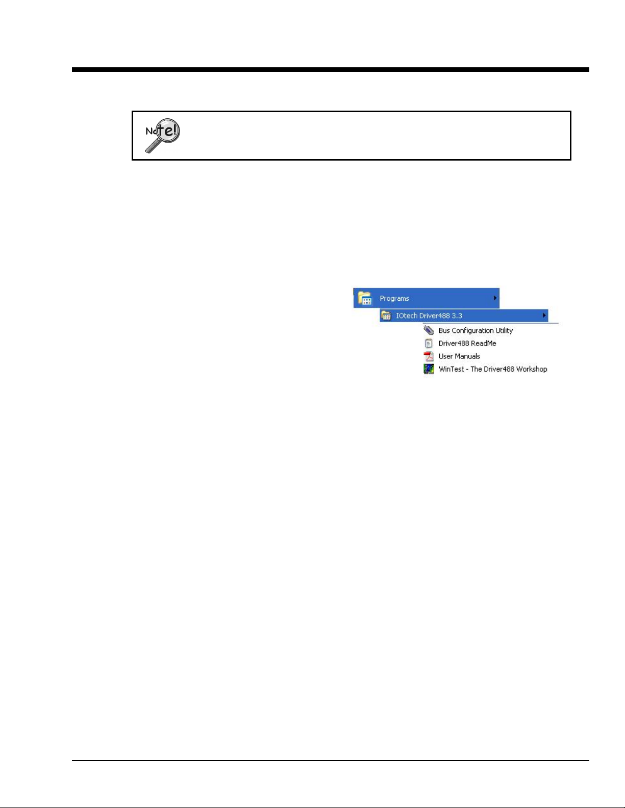
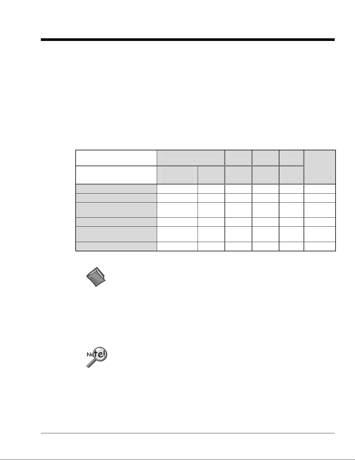
Personal488 Overview 1
Personal488 Hardware Plug-and-Play Bus Type and
Transfer Rate
Personal488/PCI (with PCI488)
Personal488/ATpnp
(with AT488pnp)
Personal488/CARD
(with CARD488)
Yes
Yes
Yes
“hot swapping”
PC Card (PCMCIA)
32-bit PCI Bus
1 Mbyte/s
16-bit ISA Bus
1 Mbyte/s
1 Mbyte/s
Personal488/AT (with AT488)
No
16-bit ISA-bus
1 Mbyte/s
Personal488
(with GP488B)
*
No
8-bit ISA-bus
330 Kbyte/s
Personal488/MM
(with GP488B/MM)
*
No
* GP488 boards with serial numbers of 036731 or lower are not supported by Drivers for
Windows 9x or WindowsNT.
Note: Items pictured are not shown to the same scale.
8-bit PC/104
330 Kbyte/s
Personal488 for Windows 95/98/Me/NT/2000/XP 889496 Personal488 Overview 1-1
Page 8
Hardware Products
The family of Personal488 PC/IEEE 488 controller interfaces includes the six (6) interfaces
which are discussed in this manual. All of them are IEEE 488.2 compatible and are supported
by 32-bit Driver488 software for Windows 95, 98, Me, 2000 and NT. These interfaces are
discussed in the following Personal488 packages:
Hardware Configurations
Plug-and-Play Devices
• Personal488/PCI (PCI488)
• Personal488/ATpnp (AT488pnp)
• Personal488/Card (Card488)
Software Installation
The installation process consists of running an installation setup program, and for non plugand-play products running the Add New Hardware program found in the Windows Control
Panel. The installation setup program will automatically determine the version of Windows
(e.g. Windows 95, 98, Me, NT, 2000, or XP) and copy all the necessary drivers and support
files to the appropriate destinations. Note that on Windows systems with AutoPlay enabled,
the setup program will automatically start upon insertion of the CD.
“Non plug-and-play” Devices
• Personal488/AT (AT488)
• Personal488 (GP488B)
• Personal488/MM
Reference Notes:
¾ Refer to Chapter 4, Hardware Configuration Reference for information
concerning jumpers and switches.
¾ For hardware specifications, please refer to Appendix D of the
Personal488 User’s Manual (p/n 495-0903). A PDF version of the manual
is included on the installation CD and on our website.
Install the software before installing the hardware. Since the installation
setup program installs driver and INF files, plug-and-play boards will be
automatically configured upon first startup, thus eliminating the need to
insert the CD and browse for support files. For non plug-and-play devices
all that is required to complete the installation is to run “Add New
Hardware.” This will notify Windows that a new device exists.
Acrobat: For installing Adobe Acrobat Reader. Documentation
that has been included on the CD in the Adobe pdf format can
be viewed and printed with use of the Adobe Reader.
Driver488/DRV
Driver488/NI Includes drivers for DOS and Windows 3.1
Driver488/SUB
The Win9x_WinNT folder includes a W9X Driver Disk folder
for Windows 95 and 98; and a Win2K Driver Disk folder for
Me, NT, 2000, and XP.
After the software has been installed you
can access the full version user’s manual
PDF from the Windows Desktop by
navigating as follows: Start>Programs>
IOtech Driver488.xx>User Manuals.
Note: The CD structure is subject to change without notice.
1-2 Personal488 Overview 889496 Personal488 for Windows 95/98/Me/NT/2000/XP
Page 9
CD-ROM, Driver 488 Software Packages 2
IOtech, Inc. IEEE 488.2 Software Products
Personal488/PCI – 1 Mbyte/s PCI/IEEE 488.2 Board with Plug & Play, Digital I/O, & Software
for PCs
Personal488/Atpnp – 1 Mbyte/s PCI/IEEE 488.2 Board with Plug & Play, Digital I/O, & Software
for PCs
Personal488/AT – 1 Mbyte/s IEEE 488.2 Board & Software for PC/Ats
Personal488 – IEEE 488.2 Board & Software for PCs
Personal488/CARD – IEEE 488.2 PC-Card Interface, Cable, & Software for Notebook &
Desktop PCs
This CD contains several driver software packages for DOS and Windows. The following table
shows which Driver488 packages can be used with each IEEE 488 Controllers product type.
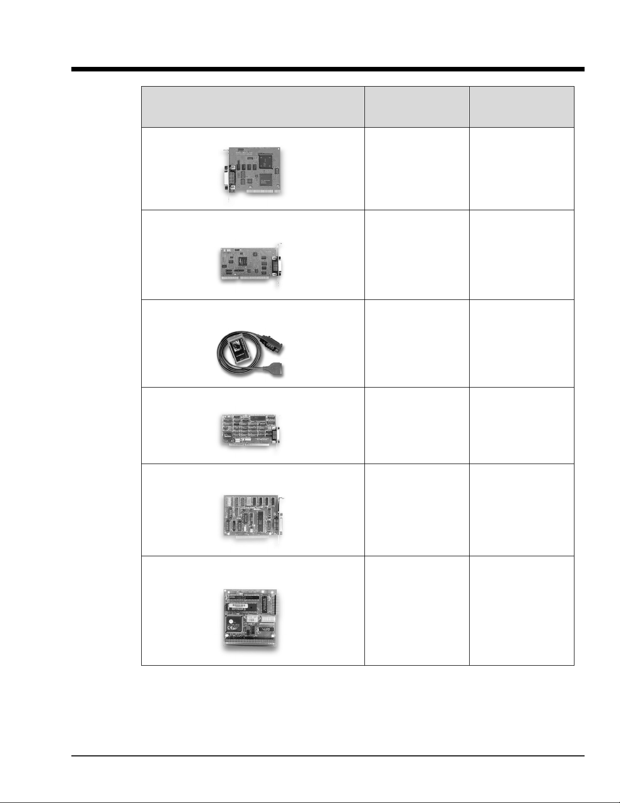
Folder (In CD Root
Directory) Æ
Supported Operating
System Æ
Personal488 (ISA)
Personal488AT (ISA)
Personal488/Atpnp
(ISA pnp)
Personal488PCI (PCI)
Personal488CARD
(PC-CARD)
Personal 488MM (PC104)
Win9x_WinNT W31 DRV SUB
2000, XP,
Me, and 9x
9 9 9 9 9 9
9 9 9 9 9 9
9
9 9
9
9 9 9 9 9 9
NT 3x DOS DOS
No No No No
No No No
No
9 9 9 9
(*) Reference Note:
Information pertaining to National Instruments (NI) is provided in
Appendix E of the full version PDF manual (p/n 495-0903). If needed,
see page v in regard to accessing the PDF manual.
The CD contains all of the Driver488 packages available for current IEEE 488 Controller
products. The various driver packages are organized according to the directory tree
structure as indicated on page 1-2.
Before running any of the installation programs, please look for a readme file in the same directory as the install program. When present, it
may contain important installation instructions.
NI
(*)
9
9
Personal488 for Windows 95/98/Me/NT/2000/XP 889496 CD-ROM, Driver 488 Software Packages 2-1
Page 10

Driver488 Packages
Driver488/DRV
IEEE 488.2 DOS Device Driver Software.
• Supports IOtech’s AT488, GP488B, CARD488, NB488, GP488B/MM, MP488, MP488CT
series boards.
• Includes “ON SRQ” program vectoring for Basic, C, Pascal.
• Compatible with all popular programming languages and spreadsheets.
• Automatically loads into high memory when available.
Driver488/SUB
IEEE 488.2 DOS Subroutine Driver.
• Supports IOtech’s AT488, GP488B, CARD488, NB488, GP488B/MM, MP488, MP488CT
series boards.
• Includes “ON SRQ” program vectoring for Basic, C, Pascal.
• Compatible with popular programming languages and spreadsheets such as C, Pascal
and QuickBasic.
Driver488/W31
IEEE 488.2 Microsoft Windows Dynamic Link Library
• Supports IOtech’s AT488, GP488B, CARD488, NB488, GP488B/MM, MP488, MP488CT
series boards.
• Offers HP-style commands for high & low-level control.
• Designed for Windows’ message passing, multi-tasking architecture.
• Includes language interfaces for Microsoft C, Visual C++, Visual Basic, Turbo C,
Borland C++.
• Includes an interactive control application for exercising instruments and generating
code.
• On-Line Help provides complete command reference as well as examples.
Win9x_WinNT Folder
This folder includes IEEE 488.2 drivers for the following operating systems: Windows 9x,
Windows Me, Windows 2000, Windows XP, and Windows NT.
The setup program automatically detects the operating system and installs the correct drivers.
• In regard to Windows 9x, Windows Me, Windows 2000, and Windows XP, the drivers
support IOtech’s AT488, GP488B, GP488B/MM, PCI488 series boards.
• Integrate IEEE 488.2 control into Microsoft Windows applications.
• Provide true multi-tasking device locking.
• Were specifically designed for the 32-bit Windows environment.
2-2 CD-ROM, Driver 488 Software Packages 889496 Personal488 for Windows 95/98/Me/NT/2000/XP
Page 11
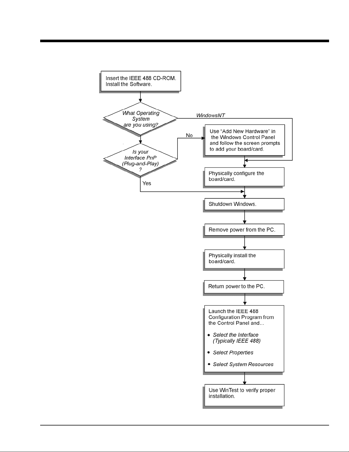
Installation 3
IEEE 488 Installation Flowchart
Windows95/98
/Me/2000/XP
Windows 95 Users …… 3-2
Windows 98 Users …… 3-5
Windows Me Users …… 3-8
Windows NT Users …… 3-11
Windows 2000 & XP Users …… 3-13
Personal488 for Windows 95/98/Me/NT/2000/XP 889496 Installation 3-1
Page 12
Windows 95 Users
Software Installation
Step 1
Insert the IEEE488 Software CD. The CD has an auto-run program that will automatically start the
setup program when the CD is inserted into the CD ROM driver. If auto-run is disabled, use Explorer to
launch the Setup.exe found in the root directory of the CD. Follow the screen prompts to install the
software. If non plug-and-play hardware is being installed, proceed to step 2; otherwise proceed to
“Hardware Installation” on page 3-4.
Step 2
Use the “Add New Hardware” program found in the Control Panel to notify Windows 95 that you are
installing new hardware. Refer to the following steps that demonstrate the typical Windows panels
encountered during the “Add New Hardware” program execution:
⇒
Start
Settings ⇒ Control Panel ⇒ Add New Hardware
• For best results, install the interface after the software installation.
• Due to differences in Windows 95 “Add New Hardware” panels, the following
description may vary slightly.
• If installing a second non plug-and-play interface, skip step 1.
• If installing a second plug-and-play interface, go to “Hardware Installation.”
Add New Hardware Procedure (non plug-and-play users only):
It is only necessary for users of “non plug-and-play” boards to follow the Add New
Hardware Procedure. If your device is a “plug-and-play device,” skip this procedure.
1. The “Add New Hardware Wizard” displays an introductory message and prompts you to click Next.
2. Windows 95 will automatically search for hardware. Click Next.
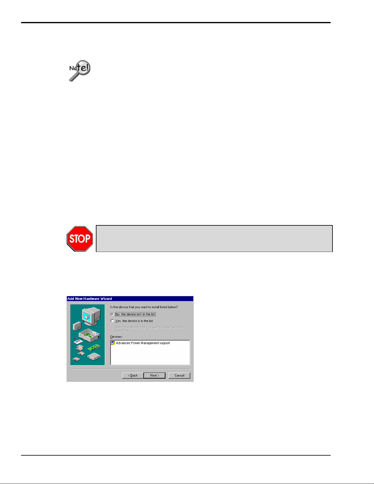
3. Click ‘No, the device isn’t in the list’
3-2 Installation 889496 Personal488 for Windows 95/98/Me/NT/2000/XP
Page 13

Windows 95
4. Select the option:
“No, I want to select the
hardware from a list,” then click
Next.
Choose IEEE488.2 Controllers from the list of hardware types and click Next.
5. Windows will now display a list of devices to install.
Select your specific Personal488 interface product. Example Personal488/AT
After making the selection, click Next.
Windows will now display the default resource settings for your interface.
6. Make note of the displayed
settings, as you must configure
the jumpers and switch settings
before installing an AT488 or
GP488B
7. Click Finish.
Click Yes, proceed with Windows 95 Hardware Installation.
Personal488 for Windows 95/98/Me/NT/2000 889496 Installation 3-3
Page 14

Windows 95
Hardware Installation for Windows 95 Users
Plug-and-Play Devices
Personal488/PCI
Personal488/ATpnp
Personal488/Card
1. If you have not already done so, shutdown Windows 95 after the IEEE 488 software has been
successfully installed.
2. Remove power from the PC.
3. Physically install your interface. As a quick reference,
Personal488/PCI installs into a 32-bit PCI expansion slot,
Personal488/ATpnp installs into a 16-bit ISA expansion slot, and
Personal488/Card installs into a PC card slot.
4. Return power to the PC. After the computer powers up, Windows will detect your new hardware.
At this point refer to the full-version PDF. See page v for location.
“Non plug-and-play” Devices
Personal488/AT (AT488)
Personal488 (GP488Bplus)
Personal488/MM
1. Verify that Windows 95 has properly shutdown.
2. Remove power from the PC.
3. Physically configure the device’s jumpers and switches to match the resource settings Windows
reported during the driver installation.
Non plug-and-play board users: physically configure your board’s jumpers and switches
to match the resource settings Windows reported. If these settings conflict with other
hardware, change the jumpers, switches, and Windows Resource settings to available
resources.
Reference Note:
Refer to Chapter 4, Hardware Configuration Reference for further information
concerning jumpers and switches.
4. Physically install your interface.
5. Return power to the PC.
At this point refer to the full-version PDF. See page v for location.
3-4 Installation 888996 Personal488 for Windows 95/98/Me/NT/2000/XP
Page 15

Windows 98 Users
Software Installation
Step 1
Insert the IEEE488 Software CD. The CD has an auto-run program that will automatically start the
setup program when the CD is inserted into the CD ROM driver. If auto-run is disabled, use Explorer
to launch the Setup.exe found in the root directory of the CD. Follow the screen prompts to install the
software. Then, if non plug-and-play hardware is being installed, proceed to step 2; otherwise proceed
to hardware installation on page 3-7.
Step 2
Use the “Add New Hardware” program found in the Control Panel to notify Windows 98 that you are
installing new hardware. Refer to the following steps that demonstrate the typical Windows panels
encountered during the “Add New Hardware” program execution:
⇒
Start
Settings ⇒ Control Panel ⇒ Add New Hardware
• For best results, install the interface after the software installation.
• If installing a second non plug-and-play interface, skip step 1.
• If installing a second plug-and-play interface, go to Hardware Installation, page 3-7.
Add New Hardware Procedure (non plug-and-play users only):
It is only necessary for users of “non plug-and-play” boards to follow the Add New
Hardware Procedure. If your device is a “plug-and-play device,” skip this procedure.
The “Add New Hardware Wizard” displays an introductory message and prompts you to click Next.
1. Click Next.
2. Select ‘No, the device isn’t in the
list’ and click Next.
3
Personal488 for Windows 95/98/Me/NT/2000/XP 889496 Installation 3-5
Page 16

Windows 98
3. Select ‘No, I want to select the
hardware from a list’ and click
Next.
4. Select ‘IEEE 488.2 Controllers’ and click Next.
5. Windows will now display a list of devices to install. Select your specific Personal488 interface
product. Example Personal488/AT
6. After making the selection,
click Next.
Windows will now display the default resource settings for your interface.
7. Make note of the displayed settings,
as you must configure the jumpers
and switch settings before installing
an AT488 or GP488B.
8. Click Finish.
9. Click ‘Yes’ and shut down the computer; then proceed to the next step.
3-6 Installation 889496 Personal488 for Windows 95/98/Me/NT/2000/XP
Page 17

Hardware Installation for Windows 98 Users
Plug-and-Play Devices
Personal488/PCI
Personal488/ATpnp
Personal488/Card
1. If you have not already done so, shutdown Windows 98 after the IEEE 488 software has been
successfully installed.
2. Remove power from the PC.
3. Physically install your interface. As a quick reference,
Personal488/PCI installs into a 32-bit PCI expansion slot,
Personal488/ATpnp installs into a 16-bit ISA expansion slot, and
Personal488/Card installs into a PC card slot.
4. Return power to the PC. Windows will detect your new hardware when the computer powers up.
At this point refer to the full-version PDF. See page v for location.
“Non plug-and-play” Devices
Personal488/AT (AT488)
Personal488 (GP488B)
Personal488/MM
1. If you have not already done so, shutdown Windows 98 after the IEEE 488 software has been
successfully installed.
Windows 98
2. Remove power from the PC.
3. Physically configure the device’s jumpers and switches to match the resource settings Windows
reported during the driver installation.
Non plug-and-play board users: physically configure your board’s jumpers and switches
to match the resource settings Windows reported. If these settings conflict with other
hardware change the jumpers, switches, and Windows Resource settings to available
resources.
Reference Note:
Refer to Chapter 4, Hardware Configuration Reference for further information concerning
jumpers and switches.
4. Return power to the PC.
At this point refer to the full-version PDF. See page v for location.
Personal488 for Windows 95/98/Me/NT/2000/XP 889496 Installation 3-7
Page 18

Windows Me Users
Software Installation
Step 1
Insert the IEEE488 Software CD. The CD has an auto-run program that will automatically start the
setup program when the CD is inserted into the CD ROM driver. If auto-run is disabled, use Explorer
to launch the Setup.exe found in the root directory of the CD. Follow the screen prompts to install the
software. Then if non plug-and-play hardware is being installed, proceed to step 2; otherwise proceed
to Hardware Installation for Windows Me Users on page 3-10.
Step 2
Use the “Add New Hardware” program found in the Control Panel to notify Windows Me that you are
installing new hardware. Refer to the following steps that demonstrate the typical Windows panels
encountered during the “Add New Hardware” program execution:
⇒
Start
Settings ⇒ Control Panel ⇒ Add New Hardware
• For best results, install the interface after the software installation.
• If installing a second non plug-and-play interface, skip step 1.
• If installing a second plug-and-play interface, go to “Hardware Installation.”
Add New Hardware Procedure (non plug-and-play users only):
It is only necessary for users of “non plug-and-play” boards to follow the Add New
Hardware Procedure. If your device is a “plug-and-play device,” skip this procedure.
The “Add New Hardware Wizard” displays an introductory message and prompts you to click Next.
1. Click Next.
2. Select ‘No, the device isn’t in the
list’ and click Next.
3-8 Installation 889496 Personal488 for Windows 95/98/Me/NT/2000/XP
Page 19

Windows Me
3. Select ‘No, I want to select the
hardware from a list’ and click
Next.
4. Select ‘IEEE 488.2 Controllers’ and click Next.
5. Windows will now display a list of devices to install. Select your specific Personal488 interface
product. Example Personal488/AT
6. After making the selection, click Next.
Windows will now display the default resource settings for your interface.
7. Make note of the displayed settings,
as you must configure the jumpers
and switch settings before installing
an AT488 or GP488B.
8. Click Finish.
9. Click ‘Yes’ and shut down the computer.
At this point, proceed to the next section, Hardware Installation for Windows Me Users.
Personal488 for Windows 95/98/Me/NT/2000/XP 889496 Installation 3-9
Page 20

Windows Me
Hardware Installation for Windows Me Users
Plug-and-Play Devices
Personal488/PCI
Personal488/ATpnp
Personal488/Card
1. If you have not already done so, shutdown Windows Me after the IEEE 488 software has been
successfully installed.
2. Remove power from the PC.
3. Physically install your interface. As a quick reference,
Personal488/PCI installs into a 32-bit PCI expansion slot,
Personal488/ATpnp installs into a 16-bit ISA expansion slot, and
Personal488/Card installs into a PC card slot.
4. Return power to the PC. After the computer powers up, Windows Me will detect your new hardware.
At this point refer to the full-version PDF. See page v for location.
“Non plug-and-play” Devices
Personal488/AT (AT488)
Personal488 (GP488B)
Personal488/MM
1. If you have not already done so, shutdown Windows Me after the IEEE 488 software has been
successfully installed.
2. Remove power from the PC.
3. Physically configure the device’s jumpers and switches to match the resource settings Windows Me
reported during the driver installation.
Non plug-and-play board users: physically configure your board’s jumpers and switches
to match the resource settings Windows reported. If these settings conflict with other
hardware change the jumpers, switches, and Windows Resource settings to available
resources.
Reference Note:
Refer to Chapter 4, Hardware Configuration Reference for further information concerning
jumpers and switches.
4. Return power to the PC.
At this point refer to the full-version PDF. See page v for location.
3-10 Installation 889496 Personal488 for Windows 95/98/Me/NT/2000/XP
Page 21

Windows NT Users
Software Installation
Step 1
Insert the IEEE488 Software CD. The CD has an auto-run program that will automatically start the
setup program when the CD is inserted into the CD ROM driver. If auto-run is disabled, use Explorer
to launch the Setup.exe found in the root directory of the CD.
Step 2
Follow the screen prompts to install the software, then proceed to hardware installation.
Hardware Installation
All Devices
Personal488/AT (AT488)
Personal488 (GP488Bplus)
Personal488/MM
Personal488/PCI
1. Access the Windows Control Panel and launch the IEEE488 configuration program.
2. Highlight your interface (typically IEEE0) and select Properties as shown below:
Selecting “Properties” and “System Resources”
3. Click the Systems Resources button.
If Personal488/PCI is selected, then the System Resources button is not available. Windows
NT is not a plug-and-play operating system, and thus changing resources on a Plug-and-Play
interface is not possible.
Personal488 for Windows 95/98/Me/NT/2000/XP 889496 Installation 3-11
Page 22

Windows NT
4. Physically configure the device’s jumpers and switches to match the resource settings Windows is
reporting during the driver installation. If these settings conflict with other hardware, change the
jumpers, switches, and Windows Resource settings to available resources.
Reference Note:
Refer to Chapter 4, Hardware Configuration Reference, for more information
regarding jumpers and switches.
5. Shutdown Windows and remove power from your PC.
6. Insert the interface board, securing it appropriately.
7. Return power to the PC.
At this point refer to the full-version PDF. See page v for location.
3-12 Installation 889496 Personal488 for Windows 95/98/Me/NT/2000/XP
Page 23

Windows 2000 and Windows XP Users
Note: Although Windows 2000 is mentioned in the following text, users of XP should be able to easily
follow these same instructions, with minor, but obvious exceptions. This is due to the fact that the
procedure for Windows XP is very close to that of Windows 2000.
Software Installation
• For best results, install the interface after the software installation.
• If installing a second non plug-and-play interface, skip step 1.
• If installing a second plug-and-play interface, go to Hardware Installation, page 3-16.
Step 1
Insert the IEEE488 Software CD. The CD has an auto-run program that will automatically start the
setup program when the CD is inserted into the CD ROM driver. If auto-run is disabled, use Explorer
to launch the Setup.exe found in the root directory of the CD. Follow the screen prompts to install the
software. Then, if non plug-and-play hardware is being installed, proceed to step 2; otherwise proceed
to hardware installation on page 3-16.
Step 2
Use the “Add New Hardware” program found in the Control Panel to notify Windows 2000 that you
are installing new hardware. Refer to the following steps that demonstrate the typical Windows panels
encountered during the “Add New Hardware” program execution:
⇒
Start
Settings ⇒ Control Panel ⇒ Add New Hardware
Add New Hardware Procedure (non plug-and-play users only):
It is only necessary for users of “non plug-and-play” boards to follow the Add New
Hardware Procedure. If your device is a “plug-and-play device,” skip this procedure.
1. After the Add/Remove Hardware Wizard appears, click Next.
2. Select
Add/Troubleshoot a device.
3. Click Next.
The Add/Remove Hardware Wizard searches for new plug-and-play hardware.
After new hardware is located a screen, similar to that at the left, appears.
4. Select
Add a new device.
5. Click Next.
Personal488 for Windows 95/98/Me/NT/2000/XP 889496 Installation 3-13
Page 24

Windows 2000 & Windows XP
6. When prompted by the question,
“Do you want Windows to search for
your new hardware?”
Select ‘No, I want to select the
hardware from a list.’
7. Click Next.
8. When asked what type of hardware
you want to install, select
Other devices.
9. Click Next.
Windows will display a list of
manufacturers and device models.
10. Select IOtech Inc.
11. Select your sp ecific Personal488
interface product.
12. Click Next.
3-14 Installation 889496 Personal488 for Windows 95/98/Me/NT/2000/XP
Page 25

Windows 2000 & Windows XP
13. Click Next.
Windows 2000 will install software
for the device.
If Windows could not detect any
hardware settings for the device, a
message box informs you that
hardware settings must be entered
(see the following figure).
14. If Windows could not detect any
hardware settings, as indicated by the
message in step 14, enter the settings.
Refer to Hardware Configuration
Reference (chapter 4) for setting
information.
15. When prompted that “Windows is
ready to install drivers for your new
hardware,” click Next.
Windows will inform you that the hardware was installed.
16. Click Finish.
Now proceed to the next section, Hardware Installation for Windows 2000 and Windows XP Users.
Personal488 for Windows 95/98/Me/NT/2000/XP 889496 Installation 3-15
Page 26

Windows 2000 & Windows XP
Hardware Installation for Windows 2000 & Windows XP Users
Note: Although Windows 2000 is mentioned in the following text, users of Windows XP should be able to
easily follow these same instructions, with minor, but obvious exceptions. This is due to the fact that
the procedure for Windows XP is very close to that of Windows 2000.
Plug-and-Play Devices
Personal488/PCI
Personal488/ATpnp
Personal488/Card
1. If you have not already done so, shutdown Windows 2000 after the IEEE 488 software has been
successfully installed.
2. Remove power from the PC.
3. Physically install your interface. As a quick reference,
Personal488/PCI installs into a 32-bit PCI expansion slot,
Personal488/ATpnp installs into a 16-bit ISA expansion slot, and
Personal488/Card installs into a PC card slot.
4. Return power to the PC. After the computer powers up, Windows 2000 will detect your new
hardware.
At this point refer to the full-version PDF. See page v for location.
“Non plug-and-play” Devices
Personal488/AT (AT488)
Personal488 (GP488B)
Personal488/MM
1. If you have not already done so, shutdown Windows 2000 after the IEEE 488 software has been
successfully installed.
2. Remove power from the PC.
3. Physically configure the device’s jumpers and switches to match the resource settings Windows 2000
reported during the driver installation.
Non plug-and-play board users: physically configure your board’s jumpers and switches
to match the resource settings Windows reported. If these settings conflict with other
hardware change the jumpers, switches, and Windows Resource settings to available
resources.
Reference Note:
Refer to Chapter 4, Hardware Configuration Reference for further information concerning
jumpers and switches.
4. Return power to the PC.
At this point refer to the full-version PDF. See page v for location.
3-16 Installation 889496 Personal488 for Windows 95/98/Me/NT/2000/XP
Page 27

Hardware Configuration Reference 4
Configuration Overview …… 4-1
AT488 Configurations …… 4-3
GP488B Configurations …… 4-7
GP488B/MM Configurations …… 4-11
Configuration Overview
Plug-and-Play Devices
Plug-and-play devices require no physical configuration of hardware. After installing your
software and hardware [as described in Chapters 2 and 3] the configuration is performed
automatically. Note that the plug-and-play devices are listed in the following table as a
product reference only. This chapter contains no useful information concerning plug-and-play
devices.
Non Plug-and-Play Devices
The I/O base address, IRQ, and DMA settings of non plug-and-play devices are determined
by the physical settings of jumpers and DIP switches. This chapter provides the information
necessary to configure these devices.
Plug-and-Play Devices
PCI488
AT488pnp
CARD488
Note: The device images are not shown to the same scale.
Automatic
Configuration.
Automatic
Configuration.
Automatic
Configuration.
Non Plug-and-Play Devices
AT488
GP488B
GP488B/MM
See page 4-3.
See page 4-7.
See page 4-11.
Personal488 for Windows 95/98/Me/NT/2000/XP 889496 Hardware Configuration Reference 4-1
Page 28

4-2 Hardware Configuration Reference 889496 Personal488 for Windows 95/98/Me/NT/2000/XP
Page 29

A T488 Configurations
The I/O base address, IRQ, and DMA settings are switch/jumper selectable via the following
locations on the AT488 interface board: One 2-microswitch DIP switch labeled S1, one
4-microswitch DIP switch labeled S2, two 14-pin headers labeled DACK and DRQ, and one
22-pin header labeled IRQ. The DIP switch settings, and the arrangement of the jumpers on
the headers set the hardware configuration.
For the next steps, make sure that the I/O address, IRQ, and DMA set on the interface board
are different from any existing ports in your system. A conflict results when two I/O
addresses, IRQs, or DMAs are the same. (As the exception, additional AT488 interfaces may
share the same IRQ and DMA values.) If there is a conflict, reconfigure the switch/jumper
settings. Refer to the following figures as needed.
Configuring the AT488 Interface I/O Base Address
S1
1 2 1 2
Base Address
02E1
OPEN OPEN
DACK
DRQ
5 6 7 0 1 2 3
DMA 16-Bit Channel 5
S2
IRQ
1 2 3 4
OPEN
34567
Interrupt Level 5
Interrupt
Level 5
9
1011121415
S1
1 2
OPEN
1 2
OPEN
42E1
22E102E1
1 2
OPEN
62E1
AT488 I/O Base
AT488 Default Set ti ngs
Address Selections
The factory default I/O base address is 02E1. If this creates a conflict, reset switch S1
according to the figure and following table. The register addresses will be automatically
relocated at fixed offsets from the base address. If reset, record the new Input/Output (I/O)
address being used.
Selected I/O Base
Register
Address
02E1 22E1 42E1 62E1
Automatic Offset Addresses Read Register Write Register
02E1 22E1 42E1 62E1 Data In Data Out
06E1 26E1 46E1 66E1 Interrupt Status 1 Interrupt Mask 1
0AE1 2AE1 4AE1 6AE1 Interrupt Status 2 Interrupt Mask 2
0EE1 2EE1 4EE1 6EE1 Serial Poll Status Serial Poll Mode
12E1 32E1 52E1 72E1 Address Status Address Mode
16E1 36E1 56E1 76E1 CMD Pass Through Auxiliary Mode
1AE1 3AE1 5AE1 7AE1 Address 0 Address 0/1
1EE1 3EE1 5EE1 7EE1 Address 1 End of String
The I/O base address sets the addresses used by the computer to communicate with the IEEE
488 interface hardware on the board. The address is normally specified in hexadecimal and
can be 02E1, 22E1, 42E1, or 62E1. The registers of the IOT7210 IEEE 488 controller chip
and other auxiliary registers are then located at fixed offsets from the base address.
Most versions of Driver488 are capable of managing as many as four IEEE 488 interfaces. To
do so, the interface configurations must be arranged to avoid conflict amongst themselves.
No two boards may have the same I/O address; but they may, and usually should, have the
same DMA channel and interrupt level.
Personal488 for Windows 95/98/Me/NT/2000/XP 889496 Hardware Configuration Reference 4-3
Page 30

Configuring the AT488 Interface Interrupt (IRQ)
S2
IRQ
S2
IRQ
1 2 3 4 1 2 3 4
OPEN OPEN
3
4
5
6
7
9
10
11
12
14
15
Interrupt
Level 3
Interrupt
Level 4
1 2 3 4
OPEN
Interrupt
Level 5
1 2 3 4
OPEN
Interrupt
Level 6
1 2 3 4
OPEN
Interrupt
Level 7
1 2 3 4 1 2 3 4 1 2 3 4 1 2 3 4 1 2 3 4
OPEN
3
4
5
6
7
9
10
11
12
14
15
Interrupt
Level 10
OPEN OPEN OPEN OPEN
Interrupt
Level 11
Interrupt
Level 12
Interrupt
Level 14
Interrupt
Level 15
1 2 3 4
OPEN
Interrupt
Level 9
AT488 Inter rupt Selections
The factory default Interrupt (IRQ) is 5. If this creates a conflict, reset switch S2 and
jumper IRQ according to the figure. The switch and jumper settings must both indicate
the same interrupt level for correct operation with interrupts. If reset, record the new
Interrupt (IRQ) being used.
The AT488 interface board may be set to interrupt the PC on the occurrence of certain
hardware conditions. The main board interrupt may be set to IRQ level 3 through 7, 9
through 12, 14, or 15. Interrupts 10 through 15 are only available in a 16-bit slot on an ATclass machine. Interrupt 9 becomes synonymous with Interrupt 2 when used in a PC/XT bus.
The selected interrupt may be shared among several AT488s in the same PC/AT chassis. The
AT488 adheres to the “AT-style” interrupt sharing conventions. When the AT488 requires
service, the IRQ jumper determines which PC interrupt level is triggered. When an interrupt
occurs, the interrupting device must be reset by writing to an I/O address which is different
for each interrupt level. The switch settings determine the I/O address to which the board’s
interrupt rearm circuitry responds.
4-4 Hardware Configuration Reference 889496 Personal488 for Windows 95/98/Me/NT/2000/XP
Page 31

Configuring the AT488 Interface DMA Channel
The factory default DMA channel is 5. If this creates a conflict, reset jumpers DACK and DRQ
according to the figure. Both the DRQ and DACK jumpers must be set to the desired DMA
channel for proper operation. If reset, record the new DMA channel being used.
Direct Memory Access (DMA) is a high-speed method of transferring data from or to a
peripheral, such as a digitizing oscilloscope, to or from the PC’s memory. The AT class
machine has seven DMA channels. Channels 0 to 3 (8-bit), 5, 6, and 7 (16-bit) are available
only in a 16-bit slot on a PC/AT-class machine. Channel 2 is usually used by the floppy disk
controller, and is unavailable. Channel 3 is often used by the hard disk controller in PCs, XTs,
and the PS/2 with the ISA bus, but is usually not used in ATs. Channels 5 to 7 are 16-bit DMA
channels and offer the highest throughput (up to 1 Megabyte per second). Channels 0 to 3
are 8-bit DMA channels and although slower, they offer compatibility with existing GP488B and
GP488B/MM applications that only made use of 8-bit DMA channels. Under some rare
conditions, it is possible for high-speed transfers on DMA Channel 1 to demand so much of the
available bus bandwidth that simultaneous access of a floppy controller will be starved for data
due to the relative priorities of the two channels.
Personal488 for Windows 95/98/Me/NT/2000/XP 889496 Hardware Configuration Reference 4-5
Page 32

4-6 Hardware Configuration Reference 889496 Personal488 for Windows 95/98/Me/NT/2000/XP
Page 33

GP488B Configurations
6 7 8 5 2 3
14
SW1
OPEN
J5
8-Bit One Card Edge
SW1
6 7 8
5
2 3
14
IEEE 488
Connector
J3J4
J5
On-board
8 MHz Cloc k
OPEN
Interrupt
Level 5
No Wait
States
Base Address
02E1
Interrupt
Level 5
J3J4
DMA
Channel 1
GP488B Interface Board GP488B Default Settings
The I/O base address, IRQ, and DMA settings are switch/jumper selectable via the
following locations on the GP488B interface board: One 8-microswitch DIP switch labeled
SW1, two 12-pin headers labeled J3 and J4, and one 3-pin header labeled J5. The DIP
switch settings, and the arrangement of the jumpers on the headers set the hardware
configuration.
For the next steps, make sure that the I/O address, IRQ, and DMA, set on the interface
board are different from any existing ports in your system. A conflict results when two I/O
addresses, IRQs, or DMAs are the same. (As the exception, additional GP488B interfaces
may share the same IRQ and DMA values). If there is a conflict, reconfigure the
switch/jumper settings. Refer to the following figures as needed.
Selected I/O Base
Register
Address
02E1 22E1 42E1 62E1
Automatic Offset Addresses Read Register Write Register
02E1 22E1 42E1 62E1 Data In Data Out
06E1 26E1 46E1 66E1 Interrupt Status 1 Interrupt Mask 1
0AE1 2AE1 4AE1 6AE1 Interrupt Status 2 Interrupt Mask 2
0EE1 2EE1 4EE1 6EE1 Serial Poll Status Serial Poll Mode
12E1 32E1 52E1 72E1 Address Status Address Mode
16E1 36E1 56E1 76E1 CMD Pass Through Auxiliary Mode
1AE1 3AE1 5AE1 7AE1 Address 0 Address 0/1
1EE1 3EE1 5EE1 7EE1 Address 1 End of String
Personal488 for Windows 95/98/Me/NT/2000/XP 889496 Hardware Configuration Reference 4-7
Page 34

Configuring the GP488B Interface I/O Base Address
T
he factory default I/O base address is 02E1. If this creates a conflict, reset SW1 microswitches 4 and 5 according to the figure and following table. The register addresses will be
automatically relocated at fixed offsets from the base address. If reset, record the new
Input/Output (I/O) address being used.
The I/O base address sets the addresses used by the computer to communicate with the IEEE
488 interface hardware on the board. The address is normally specified in hexadecimal and
can be 02E1, 22E1, 42E1, or 62E1. The registers of the IOT7210 IEEE 488 controller chip
and other auxiliary registers are then located at fixed offsets from the base address.
Most versions of Driver488 are capable of managing as many as four IEEE 488 interfaces. To
do so, the interface configurations must be arranged to avoid conflict amongst themselves.
No two boards may have the same I/O address; but they may, and usually should, have the
same DMA channel and interrupt level.
Configuring the GP488B Interface Interrupt (IRQ)
SW1
6 7 8
5
4
6 7 8
5
4
OPEN
OPEN
6 7 8
5
4
6 7 8 5 2 3
OPEN
6 7 8
5
4
OPEN
6 7 8
5
OPEN
OPEN
2 3
1
Interrupt
Level 6
2 3
14
Interrupt
Level 7
J4
IRQ2
IRQ3
IRQ4
IRQ5
IRQ6
IRQ7
2 3
1
Interrupt
Level 2
2 3
1
Interrupt
Level 3
2 3
1
Interrupt
Level 4
14
Interrupt
Level 5
GP488B Interrupt Selection s
The factory default Interrupt (IRQ) is 5. If this creates a conflict, reset SW1 microswitches 1, 2, and 3, and jumper J4 according to the figure. The switch and jumper
settings must both indicate the same interrupt level for correct operation with
interrupts. If reset, record the new Interrupt (IRQ) being used.
4-8 Hardware Configuration Reference 889496 Personal488 for Windows 95/98/Me/NT/2000/XP
Page 35

The GP488B interface board may be set to interrupt the PC on the occurrence of certain
hardware conditions. The level of the interrupt generated is set by J4. The GP488B adheres
to the “AT-style” interrupt sharing conventions. When an interrupt occurs, the interrupting
device must be reset by writing to I/O address 02FX, where X is the interrupt level (from 0 to
7). This interrupt response level is set by switches 1, 2, and 3 of SW1 which must be set to
correspond to the J4 interrupt level setting.
Configuring the GP488B Interface DMA Channel
J3
Channel 1
Channel 2 Channel 3
GP488B DMA Channel Selections
The factory default DMA channel is 1. If this creates a conflict, reset jumper J3 according to
the figure. If reset, record the new DMA channel being used.
Direct Memory Access (DMA) is a high-speed method of transferring data from or to a
peripheral, such as a digitizing oscilloscope, to or from the PC’s memory. The PC has four
DMA channels, but Channel 0 (Disabled) is used for memory refresh and is not available for
peripheral data transfer. Channel 2 is usually used by the floppy disk controller, and is also
unavailable. Channel 3 is often used by the hard disk controller in PCs, XTs, and the PS/2 with
the ISA bus, but is usually not used in ATs. So, depending on your hardware, DMA Channels 1
and possibly Channel 3 are available. Under some rare conditions, it is possible for high-speed
transfers on DMA Channel 1 to demand so much of the available bus bandwidth that
simultaneous access of a floppy controller will be starved for data due to the relative priorities
of the two channels.
Personal488 for Windows 95/98/Me/NT/2000/XP 889496 Hardware Configuration Reference 4-9
Page 36

4-10 Hardware Configuration Reference 889496 Personal488 for Windows 95/98/Me/NT/2000/XP
Page 37

GP488B/MM PC104 Configurations
SW1
6 7 8 5 2 3
14
JP1
JP2 JP3
OPEN
GP488B/MM PC104 Interfac e Board
P1
SW1
5
OPEN
6 7 8
No Wait
States
Interrupt
Level 5
On-board
8 MHz Cloc k
2 3
14
Interrupt
Level 5
JP2 JP3
DMA
Channel 1
GP488B/MM PC104 Default Settings
JP1
The I/O base address, IRQ, and DMA settings are switch/jumper selectable via the
following locations on the GP488B/MM interface board: One 8-microswitch DIP switch
labeled SW1, two 12-pin headers labeled JP2 and JP3, and one 3-pin header labeled JP1.
The DIP switch settings and the arrangement of the jumpers [on the headers] set the
hardware configuration.
For the next steps, make sure that the I/O address, IRQ, and DMA, set on the interface
board are different from any existing ports in your system. A conflict results when two I/O
addresses, IRQs, or DMAs are the same. (As the exception, additional GP488B/MM
interfaces may share the same IRQ and DMA values). If there is a conflict, reconfigure the
switch/jumper settings. Refer to the following figures as needed.
Selected I/O Base
Register
Address
02E1 22E1 42E1 62E1
Automatic Offset Addresses Read Register Write Register
02E1 22E1 42E1 62E1 Data In Data Out
06E1 26E1 46E1 66E1 Interrupt Status 1 Interrupt Mask 1
0AE1 2AE1 4AE1 6AE1 Interrupt Status 2 Interrupt Mask 2
0EE1 2EE1 4EE1 6EE1 Serial Poll Status Serial Poll Mode
12E1 32E1 52E1 72E1 Address Status Address Mode
16E1 36E1 56E1 76E1 CMD Pass Through Auxiliary Mode
1AE1 3AE1 5AE1 7AE1 Address 0 Address 0/1
1EE1 3EE1 5EE1 7EE1 Address 1 End of String
Personal488 for Windows 95/98/Me/NT/2000/XP 889496 Hardware Configuration Reference 4-11
Page 38

Configuring the GP488B/MM PC104 Interface I/O Base Address
The factory default I/O base address is 02E1. If this creates a conflict, reset SW1 microswitches 4 and 5 according to the figure and following table. The re gister addresses will be
automatically relocated at fixed offsets from the base address. If reset, record the new
Input/Output (I/O) address being used.
The I/O base address sets the addresses used by the computer to communicate with the IEEE
488 interface hardware on the board. The address is normally specified in hexadecimal and
can be 02E1, 22E1, 42E1, or 62E1. The registers of the IOT7210 IEEE 488 controller chip
and other auxiliary registers are then located at fixed offsets from the base address.
Most versions of Driver488 are capable of managing as many as four IEEE 488 interfaces. To
do so, the interface configurations must be arranged to avoid conflict. No two boards may
have the same I/O address; but they may, and usually should, have the same DMA channel
and interrupt level.
Configuring the GP488B/MM PC104 Interface Interrupt (IRQ)
SW1
OPEN
6 7 8
5
4
6 7 8
5
4
OPEN
6 7 8
5
OPEN
OPEN
6 7 8
5
4
6 7 8
5
4
OPEN
OPEN
6 7 8
5
4
2 3
1
Interrupt
Level 5
2 3
1
Interrupt
Level 6
2 3
14
Interrupt
Level 7
JP3
IRQ2
IRQ3
IRQ4
IRQ5
IRQ6
IRQ7
2 3
1
Interrupt
Level 2
2 3
1
Interrupt
Level 3
2 3
1
Interrupt
Level 4
GP488B/MM PC104 Interrupt Selections
The factory default Interrupt (IRQ) is 5. If this creates a conflict, reset SW1 micro-switches 1,
2, and 3, and jumper JP3 according to the figure. The switch and jumper settings must both
indicate the same interrupt level for correct operation with interrupts. If reset, record the new
Interrupt (IRQ) being used.
4-12 Hardware Configuration Reference 889496 Personal488 for Windows 95/98/Me/NT/2000/XP
Page 39

The GP488B/MM interface board may be set to interrupt the PC on the occurrence of certain
hardware conditions. The level of the interrupt generated is set by JP3. The GP488B/MM
adheres to the “AT-style” interrupt sharing conventions. When an interrupt occurs, the
interrupting device must be reset by writing to I/O address 02FX, where X is the interrupt
level (from 0 to 7). This interrupt response level is set by switches 1, 2, and 3 of SW1 which
must be set to correspond to the JP3 interrupt level setting.
Configuring the GP488B/MM PC104 Interface DMA Channel
JP2
Channel 1
GP488B/MM PC104 DMA Channel Sel ec tions
Channel 2 Channel 3
The factory default DMA channel is 1. If this creates a conflict, reset jumper JP2 according to
the figure. If reset, record the new DMA channel being used.
Direct Memory Access (DMA) is a high-speed method of transferring data from or to a
peripheral, such as a digitizing oscilloscope, to or from the PC’s memory. The PC has four
DMA channels, but Channel 0 (Disabled) is used for memory refresh and is not available for
peripheral data transfer. Channel 2 is usually used by the floppy disk controller, and is also
unavailable. Channel 3 is often used by the hard disk controller in PCs, XTs, and the PS/2 with
the ISA bus, but is usually not used in ATs. So, depending on your hardware, DMA Channels 1
and possibly Channel 3 are available. Under some rare conditions, it is possible for high-speed
transfers on DMA Channel 1 to demand so much of the available bus bandwidth that
simultaneous access of a floppy controller will be starved for data due to the relative priorities
of the two channels.
Personal488 for Windows 95/98/Me/NT/2000/XP 889496 Hardware Configuration Reference 4-13
Page 40

4-14 Hardware Configuration Reference 889496 Personal488 for Windows 95/98/Me/NT/2000/XP
 Loading...