

Page 1
Personal Daq/50 S er ies Quick Start
Reference Note: If applicable, refer to (1) PDQ10, DIN Rail Kit Installatio n Guide and/or the PDQ1 and PDQ2
Personal Daq/54, /55, /56, PDQ1, and PDQ2
Before you get started
Verify that you have the following items.
• Personal Daq/50 Series Device(s)
• USB Cable
• USB Port on PC
• Data Acquisition CD
• Monitor: SVGA, 1024 x 768 screen resolution
Windows XP users:
•
PC with Intel™ Pentium, 1 GHz or equivalent;
IMPORTANT
using a Personal Daq ensure your computer’s energy save mode is disabled. If needed, consult your PC documentation.
: When using Personal Daq modules, computer energy save modes can cause false data readings. Prior to
128 MB memory; 10 GB disk space
•
Windows Vista users:
PC must be Windows Vista Premium Ready
Step 1 – Install Software
IMPORTANT
1. Remove previous version Daq drivers, if present. You can do this through Microsoft’s Add/Remove Programs feature.
2. Insert the Data Acquisition CD into your CD-ROM drive and wait for the CD to auto-run. An Opening
Screen will appear. As an alternative, you can download software from: www.mccdaq.com/software.
fte
3. A
: Software must be installed before installing hardware.
r the intro-screen appears, follow the screen prompts.
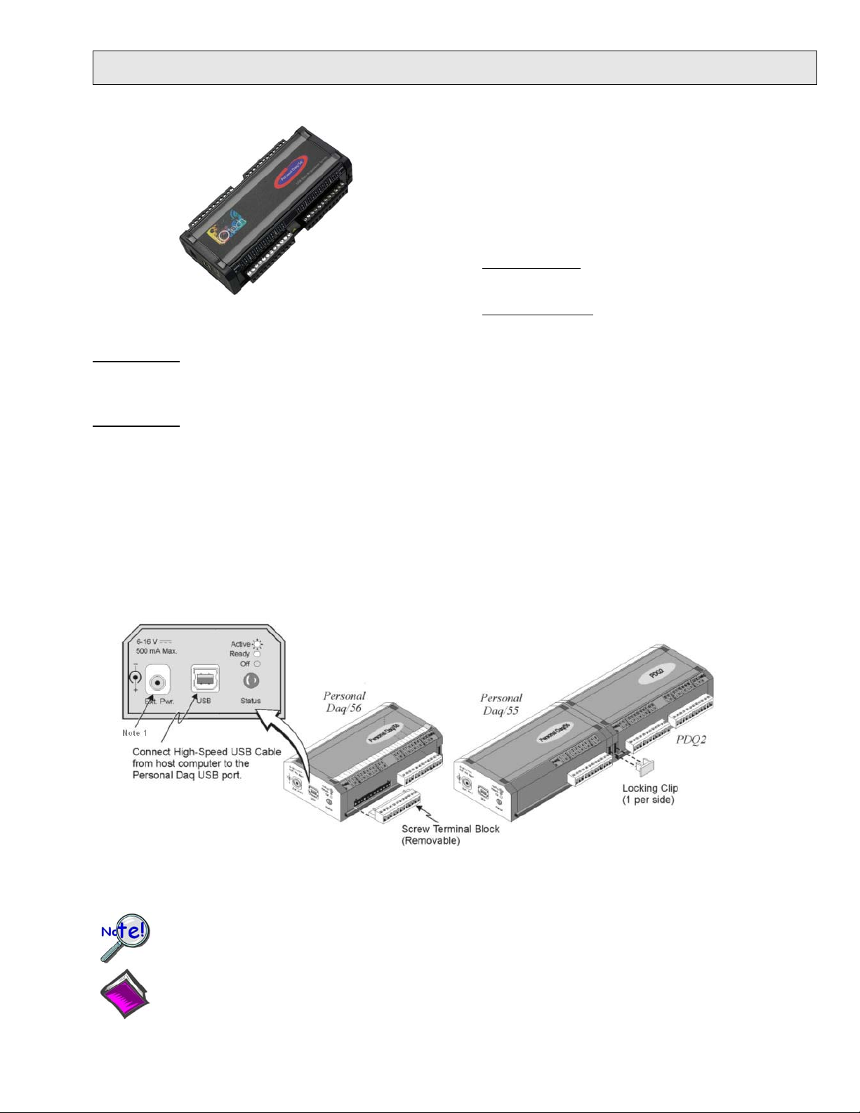
Step 2 – Connect Hardwar e
Use an approved high-speed USB cable to connect the Personal Daq system to one of the host computer’s USB ports.
Additional setup examples, involving USB hubs and power adapters, are described in the user’s manual. An expansion module
(PDQ1 or PDQ2) can be added to Personal Daq/55 and /56 units; but are not to be connected to Personal Daq/54 units, for
which there is no expansion functionality.
Note 1: Typically, there is no need to connect power to the External Power connecter. Most PC USB ports supply the
needed 500 mA at 4 to 5.25 V. However, some notebooks do not. In such cases, the Personal Daq unit will
require the use of a power adapter.
When using a power adapter with your Personal Daq system, be sure to supply power [from the adapter to the
Personal Daq] before connecting the USB cable. This allows Personal Daq to inform the host computer upon
connection of the USB cable, that the unit requires minimal power from the computer.
Installation Sheet. Note that the information is also provided in your Personal Daq User’s Manual, included in
Acrobat .pdf format on the Data Acquisition CD.
491-0940, rev 8.0 324352C-01 Printed in Hungary
Page 2
324352C-01
phone: (508) 946-5100; email: info@mccdaq.com; www.mccdaq.com Printed in Hungary
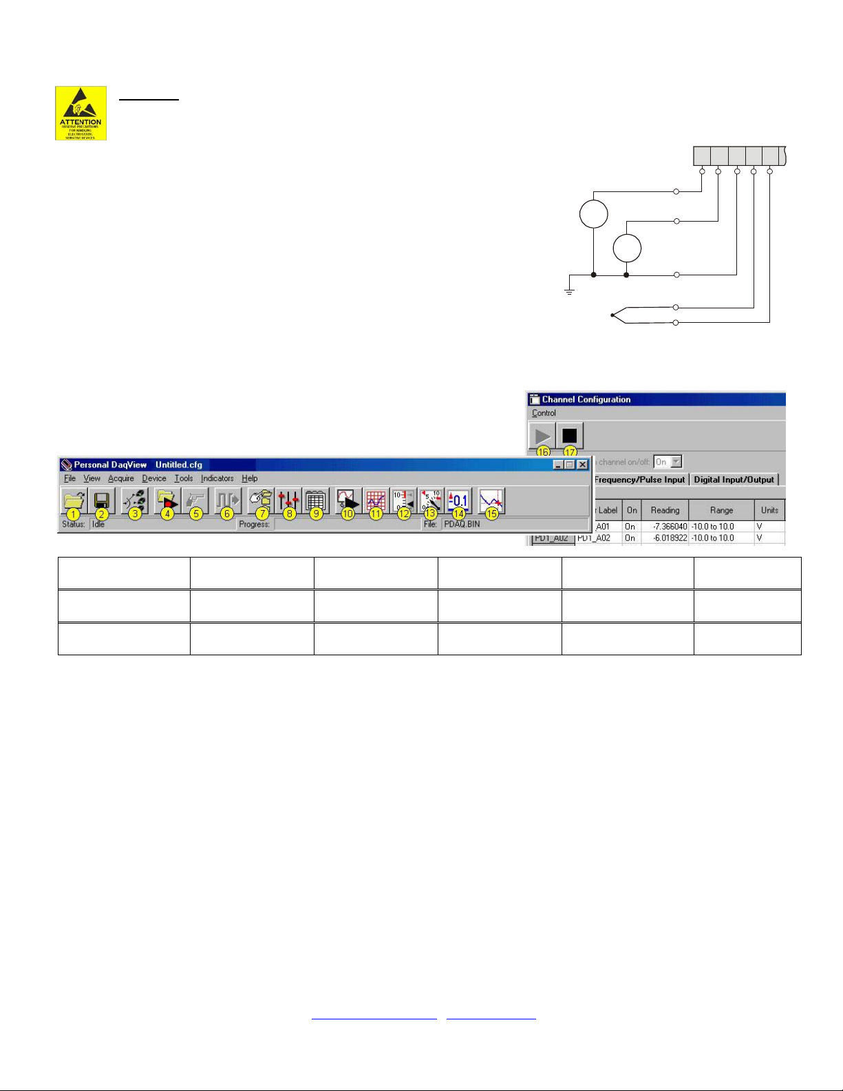
Step 3 – Connect Signal I nputs
V
V
1
2
V
3
V
3+
V
3-
COM
V1 and V2 are
Single-Ended
Inputs
Persona l Daq Terminal Block (Parti al)
V3 is a Thermocouple
and is a Differential Input
L H
C
O
M
HL
1
1 2 2
CAUTION!
appropriate ESD controlled area. Such guidelines include the use of properly grounded mats and wrist straps,
ESD bags and cartons, and related procedures.
Use Personal Daq’s screw terminals to connect channel inputs. The terminal blocks are
detachable for ease in making connections. Device labels identify input types and channel
numbers. Each Analog Input channel can be configured for single-ended or differential
volts, or for differential thermocouple inputs. The non-analog channels are designated as
Frequency/Pulse Input (F) and Digital I/O (D).
For Personal Daq, thermocouples are to be connected in differential mode only. This is
because single-ended connections can result in noise and false readings. In regard to
Differential connection, the red wire connects to the channel’s Low (L) connector; and
the second color-coded wire connects to the channel’s High (H) connector. The user’s
manual contains additional information.
Never touch connector pins or circuit components unless you are following ESD guidelines in an
Step 4 – Start Personal DaqView & Configure t he S ystem
From Windows, open Personal DaqView by double clicking on its icon, or use the
Desktop Start menu to access the program. You will find Personal DaqView
listed in the desktop’s Program group. The software will identify your Personal
Daq device and bring up the Main Control Window. This window is detailed in
the Personal Daq User’s Manual included on the installation CD.
Button Reference:
To configure channels, first click toolbar button (9). This opens the Channel Configuration Window with the Analog
Input screen selected. You can change from one configuration screen to another via three tabs (Analog Input,
Frequency/Pulse Input, Digital Input/Output).
To configure acquisition parameters, first click button (8). This opens the Configure Acquisition Window, with the
several parameters you can change, including Pre-Trigger, Trigger, Post Trigger, Averaging, and Scan Rate.
To assign a filename and folder for saving acquisition data, first click button (7). This opens the Data Destination
window. From here you can assign a filename and a folder location. Detailed information is provided in
the user’s manual.
To Collect Data: Click the <Enable Readings Column> button (16) or click, the <Update All Indicators> button (10).
This starts the acquisition. The data acquisition begins and the readings column becomes active. However, data is not
recorded to disk. Clicking the <Arm Trigger for Disk Recording> button (4) will send the data to disk. Click one of the
toolbar’s display icon buttons (11, 12, 13, or 14) to see your data in the form of a chart or meter. Note that you can view all
display types, or a combination of them, at the same time.
Note: For detailed information, view the PDF documentation located on CD, at our website, or in the Programs Group
(1) Open
Configuration File
(7) Configure
Data Destination
(13) Analog Meters (14) Digital Meters (15) View Data (16) Enable Readings
(2) Save
(8) Configure
Configuration File
Acquisition
(3) Select
Active Device
(9) Configure
Channel Settings
(4) Arm Trigger
for Disk Recording
(10) Update
All Indicators
Column
[which resides on your PC, after software installation].
*324352C-01*
Measurement Computing, 10 Commerce Way, Norton, MA 02766
(5) Manual Trigger (6) Update
(11) Scrolling Charts (12) Bar Meters
(17) Disable
Readings Column
Digital Outputs
 Loading...