

Page 1

PCM-DAS08
Analog/Digital Inputs
USER’S MANUAL
Revision 4
October, 2000
Page 2

MEGA-FIFO, the CIO prefix to data acquisition board model numbers, the PCM prefix to data
acquisition board model numbers, PCM-DAS08, PCM-D24C3, PCM-DAC02, PCM-COM422,
PCM-COM485, PCM-DMM, PCM-DAS16D/12, PCM-DAS16S/12, PCM-DAS16D/16,
PCM-DAS16S/16, PCI-DAS6402/16, Universal Library, InstaCal, Harsh Environment
Warranty and Measurement Computing Corporation are registered trademarks of Measurement
Computing Corporation.
IBM, PC, and PC/AT are trademarks of International Business Machines Corp. Windows is a
trademark of Microsoft Corp. All other trademarks are the property of their respective owners.
Information furnished by Measurement Computing Corp. is believed to be accurate and
reliable. However, no responsibility is assumed by Measurement Computing Corporation
neither for its use; nor for any infringements of patents or other rights of third parties, which
may result from its use. No license is granted by implication or otherwise under any patent or
copyrights of Measurement Computing Corporation.
All rights reserved. No part of this publication may be reproduced, stored in a retrieval system,
or transmitted, in any form by any means, electronic, mechanical, by photocopying, recording
or otherwise without the prior written permission of Measurement Computing Corporation.
Notice
Measurement Computing Corporation does not authorize any
Measurement Computing Corporation product for use in life support
systems and/or devices without the written approval of the President of
Measurement Computing Corporation Life support devices/systems are
devices or systems which, a) are intended for surgical implantation into
the body, or b) support or sustain life and whose failure to perform can
be reasonably expected to result in injury. Measurement Computing
Corp. products are not designed with the components required, and are
not subject to the testing required to ensure a level of reliability suitable
for the treatment and diagnosis of people.
(C) Copyright 2000, Measurement Computing Corporation
HM PCM-DAS08.lwp
Page 3

TABLE OF CONTENTS
1 INTRODUCTION
2 INSTALLATION
3 INTERFACING
4 PROGRAMMING & APPLICATIONS
5 I/O ADDRESS MAP & REGISTER FUNCTIONS
6 SPECIFICATIONS
7 PCM-C15-10-INCH CABLE
...............................................
...............................................
....................................................
.............................
.............................................
.....................................
....................
1
2
22.1 SOFTWARE INSTALLATION ....................................
22.2 HARDWARE INSTALLATION ...................................
3
33.1 CONNECTOR ..................................................
43.2 CONNECTING SIGNALS TO THE ANALOG INPUTS ................
53.3 GROUND LOOP EXAMPLE ......................................
53.4 BEWARE OF VOLTAGE SPIKES .................................
6
64.1 PROGRAMMING LANGUAGES ..................................
64.2 PACKAGED APPLICATIONS PROGRAMS ........................
7
75.1 CONTROL REGISTERS .........................................
75.2 REGISTER PROGRAMMING SUPPORT ...........................
75.3 CONTROL REGISTERS .........................................
105.4 A/D PACER RATE SELECTION .................................
11
13
Page 4

This page is blank.
Page 5

1 INTRODUCTION
The PCM-DAS08 is a data acquisition and control board for IBM PC compatible
computers with PCMCIA-type slots. The heart of the board is an analog to digital
converter. Analog signals are routed to the A/D converter via an 8:1 multiplexer
controlled by a register. The analog input range is fixed at +/-5V but the board can be
ordered in custom ranges.
A/D conversions can be triggered by an on-board pacer clock, an external pacer input,
or software polling.
Digital I/O lines (three in and three out) provide a means of sensing and controlling
discrete events.
1
Page 6
2 INSTALLATION
2.1 SOFTWARE INSTALLATION
Before you open your computer and install the board, install and run InstaCal™, the
installation, calibration and test utility included with your board. Refer to the
Extended Software Installation manual for InstaCal™ installation instructions.
2.2 HARDWARE INSTALLATION
Your PCM card is completely plug and play. There are no switches or jumpers to set
prior to installation in your computer. Configuration is controlled by your systems’
PCMCIA Card and Socket Services. Simply insert the PCM-DAS08 into any
available PCM slot. Refer to the orientation guide below for proper orientation of the
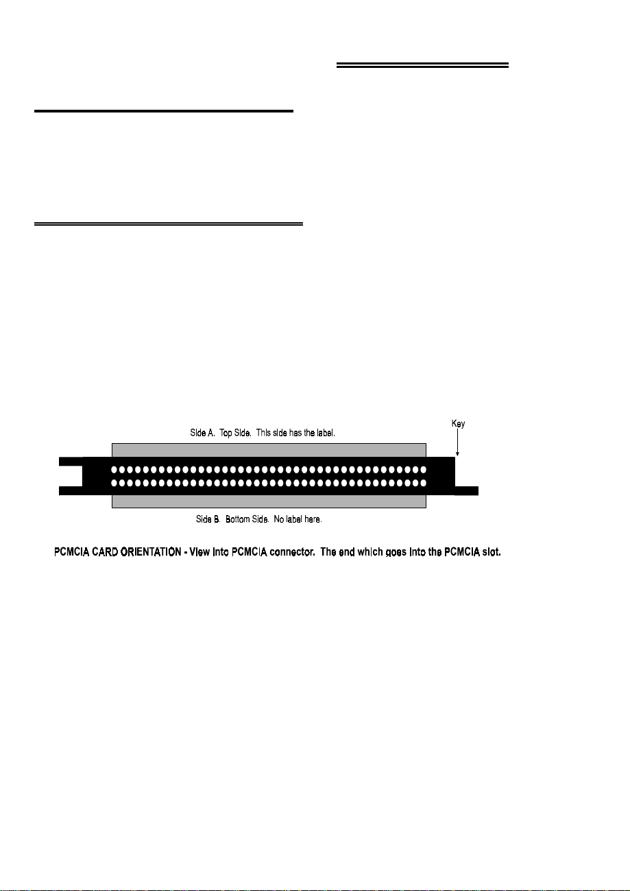
card (the typical system orients the card with the label up).
Shown here is a PCM card case looking into the connector which is inserted
into the PCMCIA slot of your computer. The KEY helps to insure that the
PCM board is inserted in the correct orientation.
Figure 2-1. PCMCIA Connector
If you are using an operating system with support for Plug and Play (such as Windows
95 or 98), a dialog box will pop up upon insertion of the card indicating that new
hardware has been detected. If the information file for this board is not already loaded
onto your PC, you will be prompted for a disk containing it. The InstaCal software
that was supplied with your board contains this file. Just insert the disk or CD and
click OK.
In order to easily test your installation, it is recommended that you install InstaCal, the
installation, calibration and test utility that was supplied with your board. Refer to the
Extended Software Installation Manual for information on the initial setup, loading,
and installation of InstaCal and optional Universal Library software.
2
Page 7

3 INTERFACING
The PCM-DAS08 has eight single-ended analog inputs with an analog ground, one
digital input with shared function as A/D trigger input, two digital inputs, and three
digital outputs. A digital ground is in the cable shield clips to either side of the 15
pins of the connector.
3.1 CONNECTOR
Figure 3-1 shows a PCM-DAS08 card looking into the connector. The KEY insures
that the cable is inserted correctly.
Analog signals should be connected with the high side to the numbered analog input
and the low side to the analog low level ground.
Do not connect digital signal grounds to the analog ground. Use the cable shield.
Figure 3-1. Interface Connector
3
Page 8

WARNING!
Do not exceed the input specifications. There are no socketed or user serviceable
parts in a PCM board.
ANALOG INPUTS are limited to +/-15V, (unlike the higher ratings of ISA
boards).
Applying a voltage below
burn out a transistor.
Please refer to specifications before
−0.5V or greater than +5V to a DIGITAL INPUT will
connecting any signals.
3.2 CONNECTING SIGNALS TO THE ANALOG INPUTS
Analog inputs are single-ended. There is a single analog ground, pin 9. When
connecting multiple channels, verify that all signal grounds are at the same potential.
Connect a DVM between any two signal grounds; the reading should be 0V.
In addition to avoiding potentials between signal grounds, also avoid potentials
between signal ground and chassis ground on your computer. If you are using a
laptop and are on battery power, the computer is floating with respect to earth ground,
but if the laptop is on the charger unit or on wall power, the laptop may be grounded.
Whenever the computer is grounded, you must connect signals so there is no potential
between PC ground and signal ground. If there is a potential, it will be added to the
signal. For example, if your sensor is supplying 3.5 volts but there is a potential of
−1.5V between the PC and the sensor ground, your A/D reading will be 2.0V instead
of 3.5V.
Figure 3-2 shows a single-ended
loop and supply a clean signal to the PCM-DAS08.
analog input connected correctly, to avoid a ground
Figure 3-2. Analog Input Connection
4
Page 9

3.3 GROUND LOOP EXAMPLE
Figure 3-3 shows a single-ended analog input connected incorrectly. The resulting
ground loop may introduce an error to the input signal.
Figure 3-3. Incorrect Connections Causing a Ground Loop
3.4 BEWARE OF VOLTAGE SPIKES
Although your Laptop may not be grounded, that does not mean that you can connect
the PCM-DAS08 to a signal that is subject to voltage spikes. Even though the Laptop
has no reference to ground, it has more capacitive mass than the PCM-DAS08 inputs
can bear. If the signal you are measuring suddenly swings greater than +/-15V, the
weak link in the circuit will fail. That weak link is your PCM-DAS08 analog input
circuit.
This is true of any A/D board not protected by isolation amplifiers
5
Page 10

4 PROGRAMMING & APPLICATIONS
Your PCM-DAS08 is now installed and ready for use. Because of the close
conformance to CIO-DAS08 register functions, many programs which work with the
CIO-DAS08 type boards will run, without modification, with the PCM-DAS08.
4.1 PROGRAMMING LANGUAGES
Universal Library provides complete access to the PCM-DAS08 functions from a
range of programming languages; both DOS and Windows. If you are planning to
write programs, or would like to run the example programs for Visual Basic or any
other language, please refer to the Universal Library manual.
4.2 PACKAGED APPLICATIONS PROGRAMS
Many packaged application programs, such as Labtech Notebook have drivers for the
PCM-DAS08. If the package you own does not appear to have drivers for the
PCM-DAS08 please fax the package name and the revision number from the install
disks. We will research the package for you and advise you on how to obtain the
correct drivers.
6
Page 11

5 I/O ADDRESS MAP & REGISTER FUNCTIONS
A base address register controls the beginning, or 'Base Address' of the I/O addresses
occupied by the control registers of the PCM-DAS08. In all, 16 addresses are
occupied (although only four have functions associated with them). The base address
assigned by CSS is stored in the CB.CBG file by InstaCal and read by the Universal
Library.
5.1 CONTROL REGISTERS
After CSS has been installed and a base address established, the PCM-DAS08 can be
controlled by writing to and reading from the control registers. While it is possible to
write your own control routines, routines have been written and are available in the
Universal Library for DOS and Windows programming languages.
5.2 REGISTER PROGRAMMING SUPPORT
While the complete register map is explained here, only very limited support for
assembly language or direct register programming is available. Register-level
programming should only be attempted by experienced programmers. We support the
use of the PCM-DAS08 through high level languages using Universal Library and the
example programs provided.
5.3 CONTROL REGISTERS
BASE + 0 - A/D LSB Data Register
Any write to this register will trigger an A/D conversion. This is a good method of
starting conversions from software or time of day clock control.
A/D Data can be read from this address and combined with data read from Base + 1 to
form a 12 bit A/D data word.
01234567
A/D0A/D1A/D2A/D3A/D4A/D5A/D6A/D7
7
Page 12

BASE + 1 - A/D MSB (4 bits)
Read data
01234567
A/D8A/D9A/D10A/D11XXXX
BASE + 2 - A/D Channel, Digital Out & Status
Write control
01234567
MA0MA1MA2XDOut0DOut1DOut2X
Set the digital output bits as 0 for a TTL low and 1 for a TTL high. You must know
the current value of the digital outputs (the last value written) if you want to change
the A/D channel and maintain the digital output lines at their current status. There is
no read back for the digital outputs.
Table 5-1. A/D Channel Address Codes
The digital outputs are latched, and will maintain the last value until overwritten or the
computer or PCM-DAS08 is reinitialized.
Set A/D channel address via MA2 MA1 MA0
Channel 0 0 0 0
Channel 1 0 0 1
Channel 2 0 1 0
Channel 3 0 1 1
Channel 4 1 0 0
Channel 5 1 0 1
Channel 6 1 1 0
Channel 7 1 1 1
8
Page 13

Read Status
01234567
EOC
Ex Trig
EOC is the end of conversion flag from the A/D converter. A one means the A/D is
busy with a conversion. A zero indicates that the conversion is complete and the data
from the most recently triggered A/D conversion may be read from base + 0 and 1.
DIn 2 / Ex Trig is always one when an external trigger source has been selected via
the TRG bits in Base + 3. Otherwise the status of the TTL input on pin 13 may be
read from this bit. See Base + 3.
Digital Input 0 and 1 are the PCM-DAS08 15 pin connector digital inputs. The
inputs are not latched. Each read gives the current status of the input lines. A zero
equals TTL low and a one equals TTL high.
MA2 to MA0 are the current A/D channel addresses.
BASE + 3 - Trigger Source & Pacer Rate
Write control - No read back. No read function
MA0MA1MA2XDIn0DIn1DIn 2
01234567
TRG 0TRG 1TRG 2INT ENAXXXX
INT ENA: Interrupt Enable. Interrupts are enabled when this bit is set to one and
disabled when set to zero.
Table 5-1. Pacing Source and Rate Coding
T
RG 2 TRG 1 TRG 0 A/D Trigger Source and Rate
0 X 0 Software trigger by writing to base address.
0 X 1 External falling-edge trigger on pin 13
1 0 0 Internally triggered and paced at 3.125 kHz
1 0 1 Internally triggered and paced at 6.25 kHz
1 1 0 Internally triggered and paced at 12.5 kHz
1 1 1 Internally triggered and paced at 25 kHz
9
Page 14

5.4 A/D PACER RATE SELECTION
The A/D pacer rate is programmable as can be seen from the list of rates in Table 5-1
above. The per channel rate is a function of both the programmed pacer and the
number of channels being sampled. Table 5-2 shows the effects of number of channels
selected on the per-channel rate.
Table 5-2. Per-Channel Rate Vs Number of Channels
3.12
kHz6.25 kHz12.5 kHz25 kHzNumber of Channels
3.136.2512.5251
1.563.136.2512.52
1.042.084.178.333
0.781.563.136.254
0.631.252.505.005
0.521.042.084.176
0.450.891.793.577
0.390.781.563.138
10
Page 15

6 SPECIFICATIONS
Typical for 25oC unless otherwise specified.
POWER CONSUMPTION
+5V (Normal operation): 30 mA typ, 69 mA max
+5V (During CIS read); 59 mA typ, 98 mA max
ANALOG INPUT SECTION
A/D converter type: ADS574
Resolution: 12 bits
Number of channels: 8, single-ended
Input Ranges: ±5V (Set at the factory. Other ranges by
special order)
Polarity Bipolar
A/D Pacing: Programmable: internal 25 kHz
divided by 1, 2, 3 or 4, external source
(DIn 2 / Ext Trig, falling edge) or software
polled
A/D Trigger sources: External polled digital input trigger (DIn
2, active level determined by software)
A/D Triggering Modes:
Digital: Software-polled digital input (software
enables acquisition when appropriate
TTL level is detected).
Data Transfer: Interrupt or software-polled
A/D conversion time 25 µs
Throughput 25 kHz, PC-dependent
Relative Accuracy (software calibrated): ±0.5 LSB
Differential Linearity error (A/D)
Integral Linearity error (A/D): ±1 LSB
No missing codes guaranteed (A/D): 12 bits
Gain drift (A/D specs): ±45 ppm/°C
Zero drift (A/D specs): ±10 ppm/°C
Input leakage current: ±200 nA over temperature
Input impedance 10 MegOhms min
Absolute maximum input voltage: ±15V
:
±1 LSB
11
Page 16

DIGITAL INPUT/OUTPUT
Digital type FPGA
Configuration Two ports, three bits each. 3 inputs / 3
outputs
Input low voltage 0.8V max
Input high voltage 2.0V min
Output low voltage (OIL = 4 mA) 0.32V max
Output high voltage (IOH = −4 mA) 3.86V min
Absolute maximum input voltage −0.5V , +5.5V
Interrupts 2 to 15
Interrupt enable Programmable
Interrupt sources External (Ext Int, falling edge triggered)
or internal pacer
ENVIRONMENTAL
Operating temperature range 0 to 70°C
Storage temperature range −40 to 100°C
Humidity 0 to 90% non-condensing
12
Page 17

7 PCM-C15-10-INCH CABLE
The PCM-C15-10-INCH is a 10-inch, 15-pin cable assembly for use with 15-pin
PCMCIA cards. It has a connector on one end and no terminations at the other end
for customer field wiring. Table 7-1 contains color coding for the 15 pins.
Table 7-1. PCM-C15-10-INCH Color Coding
COLORPINCOLORPIN
Purple9Black1
Gray10White2
Lt. Brown11Red3
Pink12Green4
White/Blue13Brown5
Blue/White14Blue6
Green/Yellow15Orange7
BareSHIELDYellow8
13
Page 18

For your notes.
14
Page 19

EC Declaration of Conformity
We, Measurement Computing Corporation, declare under sole responsibility that the
product:
Analog/Digital Input BoardPCM-DAS08
DescriptionPart Number
to which this declaration relates, meets the essential requirements, is in conformity
with, and CE marking has been applied according to the relevant EC Directives listed
below using the relevant section of the following EC standards and other normative
documents:
EU EMC Directive 89/336/EEC: Essential requirements relating to electromagnetic
compatibility.
EU 55022 Class B: Limits and methods of measurements of radio interference
characteristics of information technology equipment.
EN 50082-1: EC generic immunity requirements.
IEC 801-2: Electrostatic discharge requirements for industrial process measurement
and control equipment.
IEC 801-3: Radiated electromagnetic field requirements for industrial process
measurements and control equipment.
IEC 801-4: Electrically fast transients for industrial process measurement and control
equipment.
Carl Haapaoja, Director of Quality Assurance
Page 20

Measurement Computing Corporation
16 Commerce Boulevard,
Middleboro, Massachusetts 02346
(508) 946-5100
Fax: (508) 946-9500
E-mail: info@measurementcomputing.com
www. measurementcomputing.com
 Loading...