

Page 1

PCM-DAC08
ComputerBoards, Inc.
Revision 2
December 1998
Page 2

LIFETIME PRODUCT WARRANTY
Every ComputerBoards, Inc. product is warranted against defects in materials or workmanship
for the life of the product, to the original purchaser. Any products found to be defective in
material or workmanship will be repaired or replaced promptly.
LIFETIME HARSH ENVIRONMENT WARRANTY
Any ComputerBoards, Inc. product which is damaged due to misuse may be replaced for only
50% of the current price. I/O boards face some harsh environments, some harsher that the
boards are designed to withstand. When that happens, just return the board with an order for its
replacement at only 50% of the lis t price. ComputerBoards d oes not need to p rofit from your
misfortune. By the way, we will honor this warranty for any other manufacture’s board that we
have a replacement for!
TM
30 DAY MONEY-BACK GUARANTEE
Any ComputerBoards, Inc. product may be returned within 30 days of purchase for a full
refund of the price paid for the product being returned. If you are not satisfied, or chose the
wrong product by mistake, you do not have to keep it. Please call for a RMA number first. No
credits or returns accepted without a copy of the original invoice. Some software products are
subject to a repackaging fee.
These warranties are in lieu of all other warranties, expressed or implied, including any implied warranty
of merchantability or fitness for a particular application. The remedies provided herein are the buyer’s
sole and exclusive remedies.
Neither ComputerBoards, Inc., nor its employees shall be liable for any direct or indirect, special,
incidental or consequential damage arising from the use of its products, even if ComputerBoards has
been notified in advance of the possibility of such damages.
Notice
ComputerBoards, Inc. does not authorize any ComputerBoards, Inc.
product for use in life support systems and/or devices without the
written approval of the President of ComputerBoards, Inc. Life support
devices/systems are devices or systems which, a) are intended for
surgical implantation into the body, or b) support or sustain life and
whose failure to perfo rm can be reasonably expect ed to result in in jury.
ComputerBoards, Inc. products are not designed with the components
required, and are not subject t o the testing required to ensu re a level of
reliability suitable for the treatment and diagnosis of people.
(C) Copyright 1997 ComputerBoards, Inc.
No part of this manual may be reproduced without written permission from ComputerBoards, Inc.
Page 3

TABLE OF CONTENTS
1 INTRODUCTION
.....................................
..................
..............
.........................
......................................
.........................
...................
..............
.........................
......................................
.........................
.................
......................................
...........................
........
.........................
..............................
........................
.........................
......................
........................
.................
1
22 WINDOWS 95, 98, or NT INSTALLATION
2 2.1 INSTALL THE InstaCal SOFTWARE PACKAGE
3 2.2 INSTALL THE PCMCIA CARD
4 2.3 RUN InstaCal
5 2.4 TESTING THE INSTALLATION
63 WINDOWS 3.X OR DOS INSTALLATION
6 3.1 INSTALL THE InstaCal SOFTWARE PACKAGE
7 3.2 INSTALL THE PCMCIA CARD
7 3.3 RUN InstaCal
8 3.4 TESTING THE INSTALLATION
8 3.5 ABOUT DOS CARD & SOCKET SERVICES
104 INTERFACING
10 4.1 PCM-DAC08 CONNECTOR
11 4.2 CONNECTING DEVICES TO THE ANALOG OUTPUTS
11 4.3 OUTPUT VOLTAGE RANGES
11 4.4 SIGNAL CONNECTION
12 4.5 EXTERNAL INTERRUPT INPUT
12 4.6 DIGITAL INPUTS & OUTPUTS
135 PROGRAMMING & APPLICATIONS
13 5.1 PROGRAMMING LANGUAGES
13 5.2 PACKAGED APPLICATIONS PROGRAMS
......................................
...........................
...............
..............................
.....................
....................................
.............................
...................................
......................................
......................................
146 CALIBRATION
14 6.1 SOFTWARE CALIBRATION
157 I/O ADDRESS MAP & REGISTER FUNCTIONS
15 7.1 CONTROL REGISTERS
15 7.2 CONTROL REGISTERS ARE 8 BITS
188 SPECIFICATIONS
18 8.1 POWER CONSUMPTION
18 8.2 ANALOG INPUT
18 8.3 DIGITAL I/O
18 8.4 INTERRUPT
Page 4

1 INTRODUCTION
The PCM-DAC08 is an analog output control board for IBM PC compatible computers with PCMCIA type slots. The heart of the board is an octal 13-bit digital to analog converter . Signals are generated by the D/A via registers o n the PCM-DAC08.
Eight bidirectional digital I/O lines provide a means of sensing and controlling discrete events.
1
Page 5

2 WINDOWS 95, 98, or NT INSTALLATION
2.1 INSTALL THE InstaCal SOFTWARE PACKAGE
2.1.1 INTRODUCTION
InstaCal is the installation, calibration and test software supplied with your data acquisition / IO hardware. The complete InstaCal package is also included with the Universal Library. If you have ordered the Universal Library, use the Universal Library
disk set to install InstaCal. The installation will create all required files and unpack
the various pieces of compressed software. To install InstaCal, simply run setup.exe,
and follow the on-screen instructions.
2.1.2 INSTALLATION OPTIONS
If you are installing on a Windows 95 or 98 operating system, the "Installation
Options" dialog box will allow you to install the 16 bit, the 32 bit or both versions of
InstaCal. Select the 32 bit version unless you intend to use a 16 bit application or
library to control your data acquisition hardware.
If you are installing from the Universal Library disk set, the "Installation Options" dialog box also presents options to install example programs for each language
supported. Select the appropriate example programs for the language you will be
using.
2.1.3 FILE DEFAULT LOCATION
InstaCal will place all appropriate files in "C:\CB." If you change this default location
remember where the installed files are placed as you may need to access them later.
2.1.4 INSTALLATION QUESTIONS
At the end of the installation process there will be a series of questions: unless you
have knowledge to the contrary, simply accept the default when prompted.
2.1.5 INSTALLATION COMPLETION
After the installation of InstaCal is complete you should restart your computer to take
advantage of changes made to the system.
2
Page 6
2.2 INSTALL THE PCMCIA CARD
Your PCM card is completely plug and play. There are no switches or jumpers to set
prior to installation in your computer. Simply follow the steps shown below to install
your PCM - hardware.
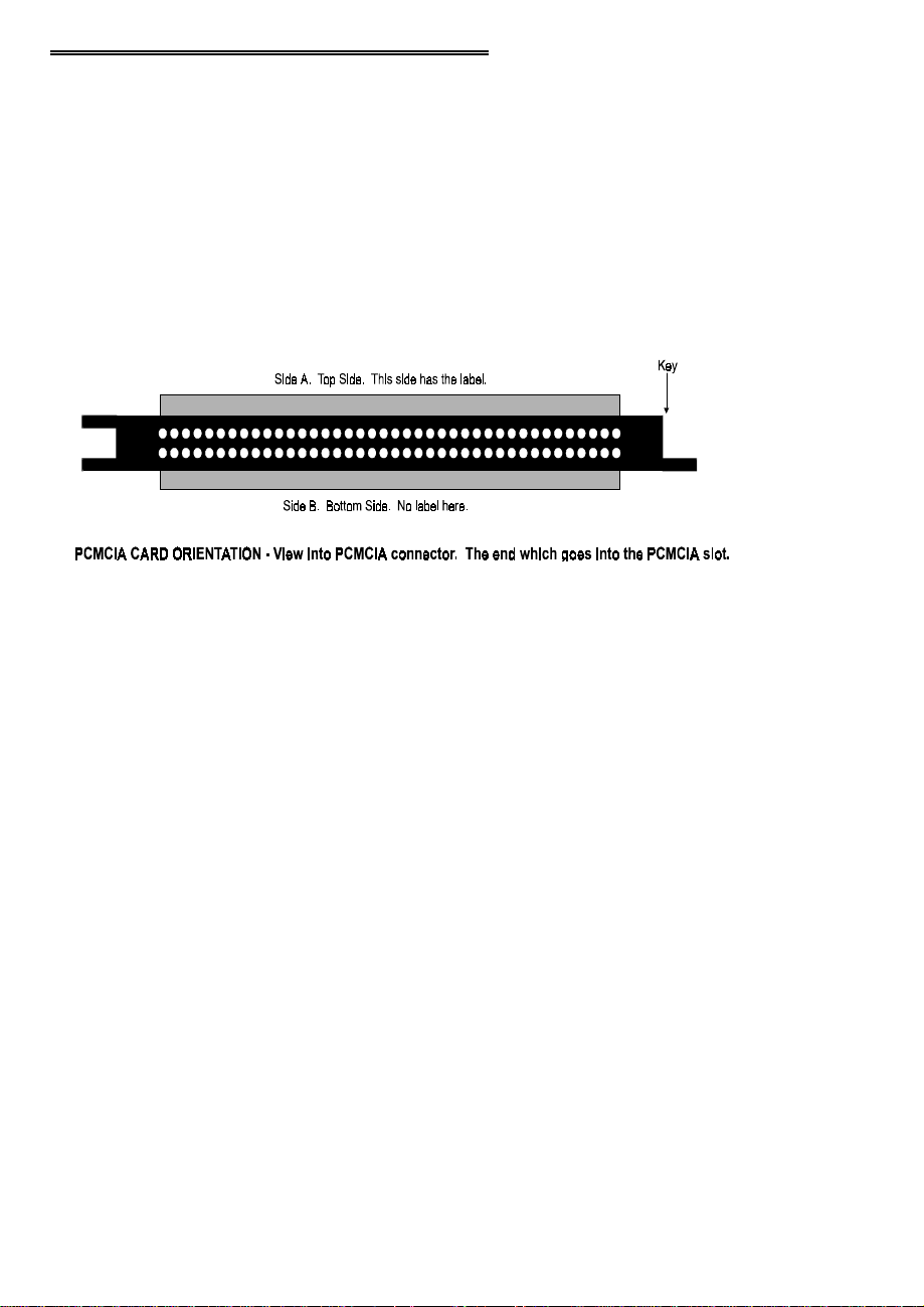
1. Insert the card into a free PC Card/PCMCIA type II or III slot. You do not
have to turn the computer off. The system is designed for power on installation. Shown here is a PCM card case looking into the connector which is
inserted into the PCMCIA slot of your computer. The KEY helps to insure
that the PCM board is inserted in the correct orientation.
2. If the appropriate drivers are already loaded on the PC, the card should be
detected, recognized, and configured by Windows and you should hear an
insertion beep. If the card is not detected by Windows, go to step 3. To verify the card has been recognized, go to Control Panel\System\Device Manager and the card should now appear under "DAS Component." If your card
appears in the list you can now proceed to the "RUN
manual.
Insta
Cal" section of this
3. If the drivers are not already loaded on the PC, you will be prompted for a
driver. If you are not prompted for a driver after inserting the card, go to
step 4. The appropriate driver is located on disk 1 of the installation disk set.
Insert this disk. Windows should detect the driver file automatically, install
it and then the card should be detected by Windows and you should hear an
insertion beep. To verify the card has been recognized, go to Control
Panel\System\Device Manager and the card should now appear under "DAS
Component." If your card appears in the list you can now proceed to the
Insta
"RUN
4. If the card is not detected by Windows and you are not prompted for a driver
after inserting the card, check that your computer's 32-bit PCMCIA drivers
are enabled. If they are not, enable them and then restart your computer and
try the above procedure again.
Cal" section of this manual.
3
Page 7

2.3 RUN InstaCal
Run the InstaCal program in order to configure the board for run-time use. By configuring the board, you add information to the configuration file, cb.cfg, that is used by
the Universal Library and other third-party data acquisition packages that use the Universal Library to access the board.
2.3.1 RUNNING THE 32 BIT VERSION
You can run the 3 2 bi t ver sion o f InstaCal b y finding the fi le named "i nscal3 2. exe" in
your installation directory and double clicking it. You can also run InstaCal by going
to your Start Menu then to Programs, then to ComputerBoards, and finally choosing
InstaCal.
If you have a P CM board inserted in a PCM slot in your computer, InstaCal di splays a
dialog box indicating the device has been detected. Simply click "OK" to proceed
with InstaCal.
If there are no other boards currently installed by InstaCal, then the PCM board will
be assigned board number 0. Otherwise it will be assigned the next available board
number.
You can now view and change t he b oa rd c onfigur atio n by c licking t he p ro per ties i con
or selecting the Install\Configure menu.
2.3.2 RUNNING THE 16 BIT VERSION
You can run the 16 bit version o f InstaCal by finding the file named "instacal.exe" in
your installation directory and double clicking it. You can also run InstaCal by going
to your Start Menu then to Programs, then to ComputerBoards, and finally choosing
"InstaCal 16."
If you have a P CM board inserted in a PCM slot in your computer, InstaCal di splays a
dialog box titled "Add PCM Card ." Select " Yes." T he next dialog box allows you to
select a board number. Choose the default (0 if no other cards are already installed)
or select a board number.
You can now select the Install menu (using the mouse or the letter "I" on the
keyboard) to view or change the configuration of the board.
4
Page 8

2.4 TESTING THE INSTALLATION
After you have run the install program, it is time to test the installation. The following
section describes the
Insta
With
Follow the instructions provided to test for proper board operation.
Cal running:
1. Select the board you just installed.
2. Select the "Test" function.
Insta
Cal procedure to test that your board is properly installed.
5
Page 9

3 WINDOWS 3.X OR DOS INSTALLATION
3.1 INSTALL THE InstaCal SOFTWARE PACKAGE
InstaCal is the installation, calibration and test software supplied with your data acqui-
sition / IO hardware. The complete InstaCal package is also included with the Universal Library. If you have ordered the Universal Library, use the Universal Library
disk set to install Instacal. The installation will create all required files and unpack the
various pieces of compressed software. To install InstaCal, simply run setup.exe, and
follow the on-screen instructions.
3.1.1 INSTALLATION OPTIONS
If you are installing from the Universal Library disk set, the "Installation Options" dialog box presents options to install libraries and example programs for each language
supported. Select the appropriate library version and example programs for the language you will be using.
If your computer does not have the Windows operating system installed (only the
DOS operating system is available), install the separate DOS-only InstaCal package
called "InstaCal for DOS, Universal Library for DOS" available from your vendor.
Computers running Windows 3.x and/or DOS need to use the DOS based Card &
Socket Services (CSS) drivers. CSS is included with most newer computers, but if
you need to purchase these drivers, they are available from your vendor (order PCM
CSS). During the InstaCal installation, you will be prompted to indicate whether or
not to install CBCLIENT. Respond "Yes." CBCLIENT is used by CSS to configure
the PCMCIA data acquisition cards. Remember, if you do not have CSS loaded,
install it before attempting to use the PCMCIA card. More information about CSS is
available in section 3.5 titled "About DOS Card & Socket Services."
InstaCal will place all appropriate files in "C:\CB." If you change this default location
remember where the installed files are placed as you may need to access them later.
At the end of the installation process there will be a series of questions: unless you
have knowledge to the contrary, simply accept the default when prompted.
After the installation of InstaCal is complete you should restart your computer to take
advantage of changes made to the system.
6
Page 10

3.2 INSTALL THE PCMCIA CARD
Insert the card into a free PCM card slot and wait for the insertion tone (a double
beep).
Shown here is a PCM card case looking into the connector which is inserted into the
PCMCIA slot of your computer. The KEY helps to insure that the PCM board is
inserted in the correct orientation.
3.3 RUN InstaCal
Run the InstaCal program in order to configure the board for run-time use. By configuring the board, you add information to the configuration file, cb.cfg, that is used by
the Universal Library and other third-party data acquisition packages that use the Universal Library to access the board.
To run InstaCal in Windows 3.x, find the file named InstaCal.exe in your installation
directory or simply double click the InstaCal.exe icon.
From DOS, jsut type "Instacal" at the DOS prompt and hit "Enter."
If you have a P CM board inserted in a PCM slot in your computer, InstaCal di splays a
dialog box titled "Add PCM Card ." Select " Yes." T he next dialog box allows you to
select a board number. Choose the default (0 if no other cards are already installed)
or select a board number.
You can now select the install menu (using the mouse or the letter "I" on the
keyboard) to view or change the configuration of the board.
7
Page 11

3.4 TESTING THE INSTALLATION
After you have run the install program and set your base address with
time to test the installation. The following section describes the
test that your board is properly installed.
Insta
With
Cal running, choose the TEST item on the main menu.
a. Select the board you just installed
b. If the choice “Internal Test” is available, then select Internal Test. If not, pro-
ceed to "e." below.
c. T he internal control registers of the board will then be tested. If this test is
successful, your board is installed correctly.
d. If the Internal Test is completed successfully, you may want to check that the
I/O pins are working correctly. To check this select External Test and follow
the instruction provided. This will require you to use the shorting wires supplied with the board to connect inputs to outputs for I/O testing. Some external tests may require an external voltage source and ohmmeter. All required
equipment and connections will be listed by
e. I f the “I/O Test Menu” lists the option “Plot”, the select it and make the con-
nections as shown to test your card.
Insta
Insta
Cal.
Insta
Cal procedure to
Cal, it is
3.5 ABOUT DOS CARD & SOCKET SERVICES
The following section describes Card & Socket Services and should help you determine whether or not you need to install CSS.
Some operating systems, such as Windows 95, include an integrated version of CSS.
If you are running such an o pera ting system, do no t install D OS CSS unless you ha ve
a specific reason to do so.
Card and socket services for your PCM card are on a disk labeled "DOS Card &
Socket Services." The software from that disk should be installed if you do not
already have CSS support on your PC.
3.5.1 WHAT IS CSS?
CSS is a program that communicates with your computers PCMCIA interface controller and configures it. The PCMCIA interface is configurable, unlike the standard ISA
8
Page 12

bus you may be familiar with. If you plug a PCMCIA board into a PCMCIA slot and
have not yet run CSS, you will have no access to the functions of that PCMCIA board.
3.5.2 DOES CSS USE SYSTEM RESOURCES?
Yes. The CardSoft Card and Socket Services device drivers which are installed in
your CONFIG.SYS use about 61K of memory. These files can be installed
DEVICEHIGH.
The CBCLIENT.EXE installed in your AUTOEXEC.BAT uses about 10K of
memory. The CBCLIENT.EXE program is a TSR (Terminate and Stay Resident).
You may modify the program line to LOADHIGH the TSR. We have tested it both
high and low with and without Windows and a variety of other applications. We
believe it is a safe TSR that will not cause any system problems.
3.5.3 HOW DO I KNOW CSS IS INSTALLED AND RUNNING?
There is a simple test. Just plug in your PCM-card. If CSS is installed and working
the computer will beep. You can remove and replace your PCM-card as often as you
like and need not power down to do so. The computer should beep each time you
insert the PCM-card.
3.5.4 WHAT ABOUT CSS FOR MULTIPLE PCM BOARDS?
Once the current version of CSS is installed, CSS is installed for all PCM boards
included in that version of CSS. As new PCM boards become available, they will be
added to the CSS and you will want to always have the most recent version of
CBCLIENT.EXE installed in the C:\CB directory. Let the installation software do
this for you.
You can run multiple PCMCIA boards with the CBCLIENT.EXE CSS, and, if you
have another CLIENT program running for other PCMCIA boards, it will not
interfere.
9
Page 13

4 INTERFACING
The PCM-DAC08 has 8 single ended analog outputs, 9 analog grounds, 1 interrupt
input, 8 digital inputs/outputs, 1 +5V output and 6 digital grounds. A chassis ground
is in the cable shield clips to either side of the 33 pins of the connector.
4.1 PCM-DAC08 CONNECTOR
Shown here is a PCM-DAC08 case looking into the connector which connect a signal
cable or screw terminal box and cable to. The KEY helps to insure that the cable is
inserted in the correct orientation.
10
Page 14

Devices to be controlled should be connected with the high side to the numbered analog output and the low side to the analog ground.
Digital signals should not be grounded to the analog ground. Use the digital ground
or the cable shield.
4.2 CONNECTING DEVICES TO THE ANALOG OUTPUTS
The PCM-DAC08 analog outputs are single ended. There is an analog ground for
each analog output channel. When connecting multiple channels you must be sure
that pin 1 is the gro und for channel 0 , pin 2 and that pin 3 i s the gro und for channel 1,
pin 4. Also, there should be no measurable potential between the grounds at pins 1, 3
7 and chassis ground.
In addition to avoiding potentials between signal grounds, you must also avoid potentials bewteen signal ground and chassis gro und on your computer. If you are using a
laptop and are on battery power, the computer is floating with respect to earth ground,
but the laptop is on the charger unit or on wall power, the laptop may be grounded.
Whenever the computer is grounded, you must connect signals so there is no potential
between PC ground and signal ground. If there is a potential, it will be added to the
signal. For example, if your PCM-DAC08 is supplying 3.5 volts and there is a potential of -1.5V between the PC and the sensor ground, your device under control will be
reading 2.0V instead of 3.5V
4.3 OUTPUT VOLTAGE RANGES
There is one possible output voltage range of ±5V.
4.4 SIGNAL CONNECTION
The outputs of the PCM-DAC08 are two wire voltage. There is a polarity associated
with the two wires and thus the outputs are labled Analog Out Channel # and Ground,
on the connector.
The maximum current supplied by the analog outputs is 2.5mA. Therefore the minimum res istanc e, or ma ximum loa d which th e outp ut may driv e is 2K O hms. Loa ds
greater than 2K Ohms will cause the analog output to droop, meaning that a code of
4095 will not be able to generate a voltage of 5V, but one somewhat less.
11
Page 15

It is best to group the ground on pin 17 with the analog output on pin 18, and the
ground on pin 19 with the analog output on pin 20, and so on.
4.5 EXTERNAL INTERRUPT INPUT
The PCM-DAC08 pin 2 is the input to a circuit which will generate an interrupt to the
computer. The inte rr up t must be enabl ed thr ough so ftware . T he inter r upt is level sensitive and is triggered on a TTL high level. TT L high is approximately 2.5V to 5V.
The interrupt signal you provide should transition from a low of o, or ground, to a
high of 5V.
The procedure initiated by an interrupt is wholly dependent on programming. Refer
to the manual for UniversalLibrary, for programmers, or Labtech or other packaged
application. UniversalLibrary provides routines for analog output as well as digital
I/O upon the detection of an interrupt.
4.6 DIGITAL INPUTS & OUTPUTS
The PCM-DAC08 has 8 bi-directional digital I/O lines. The 8 digital lines may be
programmed as input or output in groups of: 8 inputs, 8 outputs or 4 inputs & 4 outpts.
A register controls the direction of the digital I/O lines and must be set via software.
At power on or reset the digital lines default to inputs.
Please note: Digital lines in an input state present a high impedance to any device
connected to them. The implication is that if you are using a digital line to control the
input of a TTL chip, and that digital line turns from an output to an input, the T TL
chip being controlled MAY detect the turned around line as a 1 or a 0. This could
cause the TTL input being controlled to switch on or off, possibly with consequences
for the system you are controlling. To prevent random switching and force all digital
lines into a known state on power up or reset, use pull up or pull down resistors to fix
the state of the line as either high or low. A properly selected resistor will not interfere with TTL level output signals.
For more information on programming the digital I/O lines, please refer to the UniversalLibrary programmers manual..
12
Page 16

5 PROGRAMMING & APPLICATIONS
Your PCM-DAC08 is now installed and ready for use.
5.1 PROGRAMMING LANGUAGES
UniversalLibrary provides complete access to the PCM-DAC08 functions from a
range of pr ogrammaing languages; both DO S and Windows. If you ar e planning to
write programs, or would like to run the example programs for Visual Basic or any
other language, please turn now to the UniversalLibrary manual.
5.2 PACKAGED APPLICATIONS PROGRAMS
Many packaged application programs, such as Labtech Notebook and DaisyLab are
designed to operate with the CIO-DAC02 and similar boards. The control software
which controls the CIO-DAC02 is not capable of controling the PCM-DAC08. The
register set for the PCM-DAC08 is not compatible with the CIO-DAC02. You will
need drivers designed for the PCM-DAC08.
Drivers for the PCM-DAC08 for LabTech, DaisyLab and other applications may have
become available since this manual was written. Call your software manufacturer, or
ComputerBoards to find out.
13
Page 17

6 CALIBRATION
The PCM-DAC08 is software calibrated and tested at the factory. All calibration after
initial manufacturing is done via software. The calibration factors are stored on the
PCM-DAC08 and applied every time the board is run. The case may not be opened
and there are no parts inside which you can service. There are no socketed
components.
6.1 SOFTWARE CALIBRATION
If you are using the UniversalLibrary, you can set software calibration factors for offset and gain using the Calibration option of InstaCal. These factors will be applied to
outputs made by any of the D/A routines c alled fro m any of the language libr aries of
UniversalLibrary.
You will need a precision voltage source of better than 1/4095 resolution and that
voltage source must be calibrated.
It is important to note that once calibration factors have been set, they are stored in the
PCM-DAC08. These calibration factors are accessed by UniversalLibrary and InstaCal and applied to any output codes sent to the PCM-DAC08. If you use direct register programming be sure to access and apply the calibration factors. Of course, the
calibration factors may be reset at any time by runing InstaCal calibration.
Choose Calibration from the InstaCal menu, and follow the instructions. Press F1 for
help.
14
Page 18

7 I/O ADDRESS MAP & REGISTER FUNCTIONS
A base address register controls the beginning, or 'Base Address' of the I/O addresses
occupied by the control registers of the PCM-DAC08. In all, 5 addresses are occupied. Once the CSS is installed, the base address may be modified by runing the
InstaCal program. The base address assigned by InstaCal is stored in the CB.CBG file
and read by the CSS installed in your computer. Please read about installing and
using InstaCal.
7.1 CONTROL REGISTERS
Once CSS is installed and a base address has been established, the PCM-DAC08 may
be controlled by writing to and reading from the control registers. While it is possible
to write you own control routines for the PCM-DAC08, routines have been written
and are avai lab le in Uni ver salLib r ar y for DOS a nd Wi ndo ws p ro gr amming languages.
NOTE ON REGISTER PROGRAMMING SUPPORT
While the complete register map is explained here, only very limited support for
assembly language or d ir ec t r egi ster p ro gr amming is avail ab le . I f you have a que stio n
regarding dir ec t r egist er pr o gra mming, you must FAX it. T he e nginee r ing d ep ar tment
does not accept techinical support calls but will answer faxes.
The ASSEMBLY source code to the Universal Library is not available. Information
on writing interrupt service routines and other programming tasks related to the personal computer or PCMCIA slots is not available. We support the use of the PCMDAC08 through high level languages using UniversalLibrary and the example programs provided. If there is an extension to the UniversalLibrary that would be of use
to you, please FAX your request to the attention of Software Engineering.
7.2 CONTROL REGISTERS ARE 8 BITS
All I/O access may be performed as bytes or words. Eight bit addressing is controlled
by the CSS, which is currently set for 8 bit addressing as supplied by
ComputerBoards. The registers are presented in 8 bit format here.
BASE + 0 - DAC0 LSB Data Register
Any read to this register will trigger an D/A conversion. This is a good method of
starting conversions from software or time of day clock control.
15
Page 19

WRITE: D/A Data can be written to this address and to Base + 1 to form a 12 bit D/A
data word. All 8 DAC’s are updated using this register. The DAC being updated is
set via the Select bits (S3 to S0) in the Base +2 register.
READ: Starts a D/A conversion, updates the output of the selected DAC.
01234567
D/A0D/A1D/A2D/A3D/A4D/A5D/A6D/A7
BASE + 1 - DAC Value MSB (4 bits)
WRITE: Send DAC data.
READ: Clear Interrupt Request bit at Base +4 bit D#3
01234567
D/A8D/A9D/A10D/A11D/A12XXX
BASE + 2 - DAC Select Register
WRITE: Set the DAC to update
READ: Read back current DAC updating
01234567
D/A0D/A1D/A2D/A3D/A4D/A5D/A6D/A7
FUNCTION WRFUNCTION RDS0S1S2S3
Latch new D/A value for DAC0Update DAC 0 & 10000
Latch new D/A value for DAC1Update DAC 0 & 11000
Latch new D/A value for DAC2Update DAC 2 & 30100
Latch new D/A value for DAC3Update DAC 2 & 31100
Latch new D/A value for DAC4Update DAC 4 & 50010
Latch new D/A value for DAC5Update DAC 4 & 51010
Latch new D/A value for DAC6Update DAC 6 & 70110
Latch new D/A value for DAC7Update DAC 6 & 71110
Update all 8 DACs simultaneously. No write function.XXX1
Note that DACs are always updated in pairs. For example, if you latch new data to
DAC1, then update the DAC0 and DAC1 pair, DAC1 updates with the new value and
DAC0 updates with the same value as before since the latch (data for output) has not
changed.
CLR: Setting the CLR bit to 1 resets all 8 DACs output to 0V. Default and normal
operation is CLR=0, which has no effect on the DAC outputs.
BASE + 3 - Digital I/O (8 bits)
WRITE: Updates output of DIO bits set for output.
READ: Reads current status of DIO bits for input. Reads back output state of DIO
bits set for output.
16
Page 20

01234567
DIO0DIO1DIO2DIO3DIO4DIO5DIO6DIO7
BASE + 4 - Interrupt Control & Digital I/O Direction Control
WRITE: Set control bits.
READ: Read status of control bits.
01234567
LDIRUDIRINT_ENINTREQXXXX
INTREQ
Default is no interrupt has occurred = 0. When set to 1 an interrupt has occurred.
External interrupts, when enabled, occur at TTL high (2.5<TTL High<5V).
A read base+1 clears this bit.
Interrupt status routinues may want to read and verify this bit then clear it with a read
of Base +1.
INT_EN
Enable external interrupt. Enable = 1. Disable = 0.
17
Page 21

8 SPECIFICATIONS
8.1 POWER CONSUMPTION
+5V 42 mA Typical 110 mA Max during normal operation
8.2 ANALOG INPUT
Channels 8 Single Ended
Resolution 13 bits, 1 part in 8192
Slew Rate 6uSec for one full scale swing
Accuracy @13 Bits ±0.5LSB Typ, ±2LSB Max
@12 Bits ±0.25LSB Typ, ±1LSB Max
Offset Error Before Calibration ±6LSB Typ, ±22LSB Max
After Calibration ±0.5LSB Typ, ±2LSB Max
Gain Error Before Calibration ±1.5LSB Typ, ±12LSB Max
After Calibration ±1LSB Typ, ±3LSB Max
Monotonicity Guaranteed Monotonic
Output Range +/-5V
V Out Impedance < 0.1Ohm max
V Out Drive Current ± 1 mA Min.
Update Method Software Trigger, External Interrupt
Model MAX547, 13 Bit Octal DAC
8.3 DIGITAL I/O
Input 8 Bits bi-directional. May be set as 8 in, 8 out or
4 out.
Input Low Volts 0.8V
Input High Volts 2.0V
Output Low Volts 0.32V Max @ IOL = 4.0mA
Output High Volts 3.86V Max @ IOH = -4.0mA
8.4 INTERRUPT
Type Level Detect TTL High
18
Page 22

IRQ 2-5, 7, 9, 10, 15 set by CB.CFG file read by CBCLIENT.EXE
Enable Programmable.
Trigger External
19
Page 23

EC Declaration of Conformity
We, ComputerBoards, Inc., declare under sole responsibility that the product:
PCM-DAC08
DescriptionPart Number
to which this declaration relates, meets the essential requirements, is in conformity
with, and CE marking has been applied according to the relevant EC Directives listed
below using the relevant section of the following EC standards and other normative
documents:
EU EMC Directive 89/336/EEC
compatibility.
EU 55022 Class B
characteristics of information technology equipment.
EN 50082-1
IEC 801-2
and control equipment.
IEC 801-3
measurements and control equipment.
IEC 801-4
equipment.
Carl Haapaoja, Director of Quality Assurance
: Electrostatic discharge requirements for industrial process measurement
: Radiated electromagnetic field requirements for industrial process
: Electrically fast transients for industrial process measurement and control
: Limits and methods of measurements of radio interference
: EC generic immunity requirements.
: Essential requirements relating to electromagnetic
 Loading...