

Page 1

PCM-D24/CTR3
ComputerBoards, Inc.
Revision 3
March 1999
Page 2

LIFETIME PRODUCT WARRANTY
Every ComputerBoards, Inc. product is warranted against defects in materials or workmanship
for the life of the product, to the original purchaser. Any products found to be defective in
material or workmanship will be repaired or replaced promptly.
LIFETIME HARSH ENVIRONMENT WARRANTY
Any ComputerBoards, Inc. product which is damaged due to misuse may be replaced for only
50% of the current price. I/O boards face some harsh environments, some harsher than the
boards are designed to withstand. When that happens, just return the board with an order for its
replacement at only 50% of the lis t price. ComputerBoards d oes not need to p rofit from your
misfortune. By the way, we will honor this warranty for any other manufacture’s board that we
have a replacement for!
TM
30 DAY MONEY-BACK GUARANTEE
Any ComputerBoards, Inc. product may be returned within 30 days of purchase for a full
refund of the price paid for the product being returned. If you are not satisfied, or chose the
wrong product by mistake, you do not have to keep it. Please call for a RMA number first. No
credits or returns accepted without a copy of the original invoice. Some software products are
subject to a repackaging fee.
These warranties are in lieu of all other warranties, expressed or implied, including any implied warranty
of merchantability or fitness for a particular application. The remedies provided herein are the buyer’s
sole and exclusive remedies.
Neither ComputerBoards, Inc., nor its employees shall be liable for any direct or indirect, special,
incidental or consequential damage arising from the use of its products, even if ComputerBoards has
been notified in advance of the possibility of such damages.
Notice
ComputerBoards, Inc. does not authorize any ComputerBoards, Inc.
product for use in life support systems and/or devices without the
written approval of the President of ComputerBoards, Inc. Life support
devices/systems are devices or systems which, a) are intended for
surgical implantation into the body, or b) support or sustain life and
whose failure to perfo rm can be reasonably expect ed to result in in jury.
ComputerBoards, Inc. products are not designed with the components
required, and are not subject t o the testing required to ensu re a level of
reliability suitable for the treatment and diagnosis of people.
(C) Copyright 1999 ComputerBoards, Inc.
No part of this manual may be reproduced without written permission from ComputerBoards, Inc.
Page 3

TABLE OF CONTENTS
1 INTRODUCTION
.....................................
........................
..............
.........................
......................................
.........................
...................
..............
.........................
......................................
.........................
.................
.....................................
.........................
.....................
........................
................
...........................
..............
.............................
.....................
1
22 WINDOWS 95, 98 INSTALLATION
2 2.1 INSTALL THE InstaCal SOFTWARE PACKAGE
3 2.2 INSTALL THE PCMCIA CARD
4 2.3 RUN InstaCal
5 2.4 TESTING THE INSTALLATION
63 WINDOWS 3.X OR DOS INSTALLATION
6 3.1 INSTALL THE InstaCal SOFTWARE PACKAGE
7 3.2 INSTALL THE PCMCIA CARD
7 3.3 RUN InstaCal
8 3.4 TESTING THE INSTALLATION
8 3.5 ABOUT DOS CARD & SOCKET SERVICES
104 INTERFACING
10 4.1 PCM-D24/CTR3 CONNECTOR
115 PROGRAMMING & APPLICATIONS
11 5.1 PROGRAMMING LANGUAGES
11 5.2 PACKAGED APPLICATIONS PROGRAMS
126 CALIBRATION & SERVICES
137 I/O ADDRESS MAP & REGISTER FUNCTIONS
13 7.1 CONTROL REGISTERS
13 7.2 PORT ADDRESSES & FUNCTIONS
...................................
............................
.....................................
......................................
................................
208 SPECIFICATIONS
20 8.1 POWER CONSUMPTION
20 8.2 DIGITAL I/O
20 8.3 COUNTERS
21 8.4 ENVIRONMENTAL
Page 4

1 INTRODUCTION
The PCM-D24/CTR3 is a data acquisition and control board for IBM PC compatible
computers with PCMCIA type slots. The heart of the board is an 82C55 digital I/O
chip and an 82C54 counter/timer chip. Customers familiar with the CIO-DIO24/CTR3
will immediately notice the similarity in register structure and function between the
PCMCIA board and the ISA bus board.
1
Page 5

2 WINDOWS 95, 98 INSTALLATION
2.1 INSTALL THE InstaCal SOFTWARE PACKAGE
2.1.1 INTRODUCTION
InstaCal is the installation, calibration and test software supplied with your data acquisition / IO hardware. The complete InstaCal package is also included with the Universal Library. If you have ordered the Universal Library, use the Universal Library
disk set to install InstaCal. The installation will create all required files and unpack
the various pieces of compressed software. To install InstaCal, simply run setup.exe,
and follow the on-screen instructions.
2.1.2 INSTALLATION OPTIONS
If you are installing on a Windows 95 or 98 operating system, the "Installation
Options" dialog box will allow you to install the 16 bit, the 32 bit or both versions of
InstaCal. Select the 32 bit version unless you intend to use a 16 bit application or
library to control your data acquisition hardware.
If you are installing from the Universal Library disk set, the "Installation Options" dialog box also presents options to install example programs for each language
supported. Select the appropriate example programs for the language you will be
using.
2.1.3 FILE DEFAULT LOCATION
InstaCal will place all appropriate files in "C:\CB." If you change this default location
remember where the installed files are placed as you may need to access them later.
2.1.4 INSTALLATION QUESTIONS
At the end of the installation process there will be a series of questions: unless you
have knowledge to the contrary, simply accept the default when prompted.
2.1.5 INSTALLATION COMPLETION
After the installation of InstaCal is complete you should restart your computer to take
advantage of changes made to the system.
2
Page 6
2.2 INSTALL THE PCMCIA CARD
Your PCM card is completely plug and play. There are no switches or jumpers to set
prior to installation in your computer. Simply follow the steps shown below to install
your PCM - hardware.
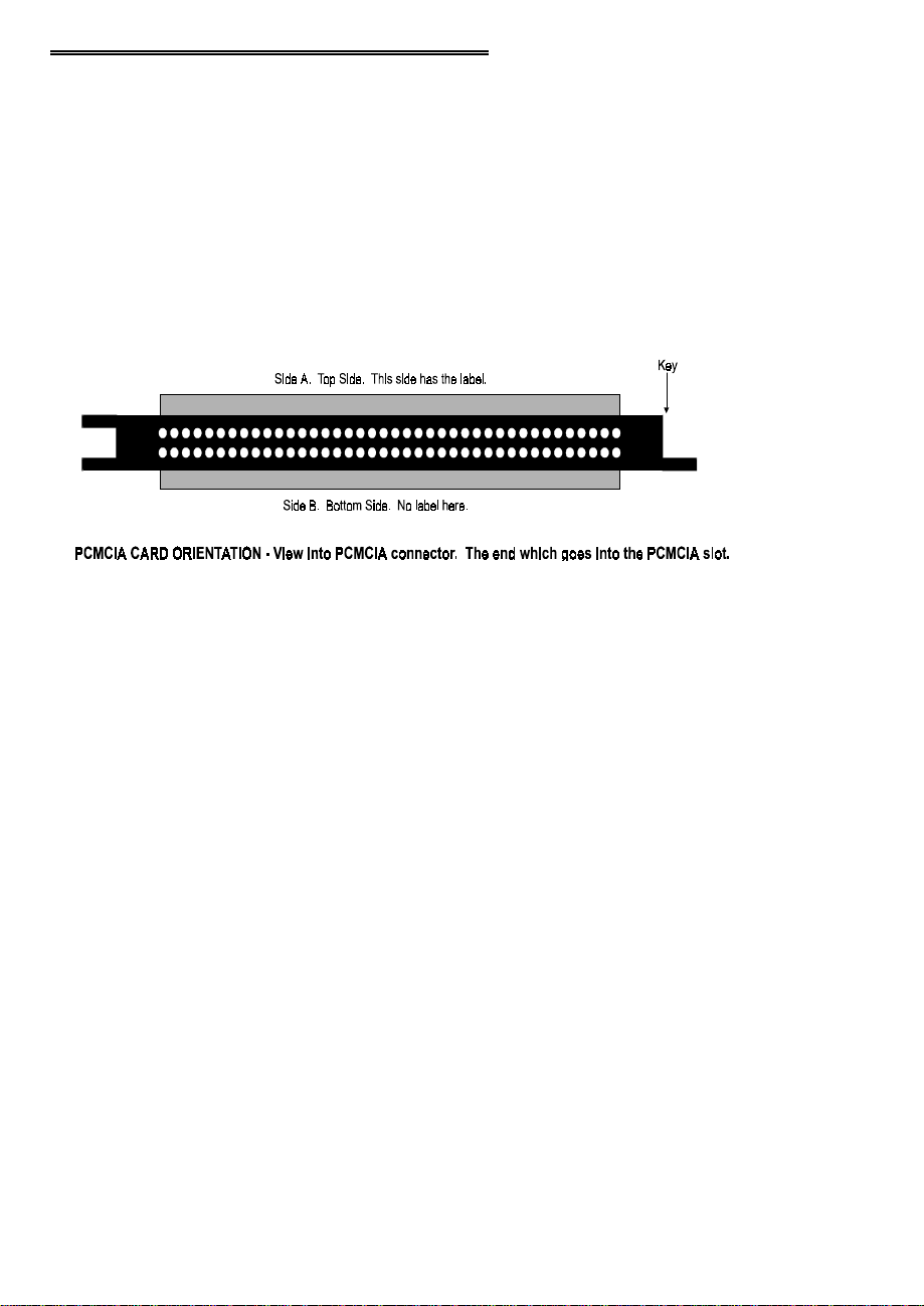
1. Insert the card into a free PC Card/PCMCIA type II or III slot. You do not
have to turn the computer off. The system is designed for power on installation. Shown here is a PCM card case looking into the connector which is
inserted into the PCMCIA slot of your computer. The KEY helps to insure
that the PCM board is inserted in the correct orientation.
2. If the appropriate drivers are already loaded on the PC, the card should be
detected, recognized, and configured by Windows and you should hear an
insertion beep. If the card is not detected by Windows, go to step 3. To verify the card has been recognized, go to Control Panel\System\Device Manager and the card should now appear under "DAS Component." If your card
appears in the list you can now proceed to the "RUN
manual.
Insta
Cal" section of this
3. If the drivers are not already loaded on the PC, you will be prompted for a
driver. If you are not prompted for a driver after inserting the card, go to
step 4. The appropriate driver is located on disk 1 of the installation disk set.
Insert this disk. Windows should detect the driver file automatically, install
it and then the card should be detected by Windows and you should hear an
insertion beep. To verify the card has been recognized, go to Control
Panel\System\Device Manager and the card should now appear under "DAS
Component." If your card appears in the list you can now proceed to the
Insta
"RUN
4. If the card is not detected by Windows and you are not prompted for a driver
after inserting the card, check that your computer's 32-bit PCMCIA drivers
are enabled. If they are not, enable them and then restart your computer and
try the above procedure again.
Cal" section of this manual.
3
Page 7

2.3 RUN InstaCal
Run the InstaCal program in order to configure the board for run-time use. By configuring the board, you add information to the configuration file, cb.cfg, that is used by
the Universal Library and other third-party data acquisition packages that use the Universal Library to access the board.
2.3.1 RUNNING THE 32 BIT VERSION
You can run the 3 2 bi t ver sion o f InstaCal b y finding the fi le named "i nscal3 2. exe" in
your installation directory and double clicking it. You can also run InstaCal by going
to your Start Menu then to Programs, then to ComputerBoards, and finally choosing
InstaCal.
If you have a P CM board inserted in a PC M slot in your computer, InstaCal displays a
dialog box indicating the device has been detected. Simply click "OK" to proceed
with InstaCal.
If there are no other boards currently installed by InstaCal, then the PCM board will
be assigned board number 0. Otherwise it will be assigned the next available board
number.
You can now view and change t he b oa rd c onfigur atio n by c licking t he p ro per ties i con
or selecting the Install\Configure menu.
2.3.2 RUNNING THE 16 BIT VERSION
You can run the 16 bit version o f InstaCal by finding the file named "instacal.exe" in
your installation directory and double clicking it. You can also run InstaCal by going
to your Start Menu then to Programs, then to ComputerBoards, and finally choosing
"InstaCal 16."
If you have a P CM board inserted in a PC M slot in your computer, InstaCal displays a
dialog box titled "Add PCM Card ." Select " Yes." T he next dialog box allows you to
select a board number. Choose the default (0 if no other cards are already installed)
or select a board number.
You can now select the Install menu (using the mouse or the letter "I" on the
keyboard) to view or change the configuration of the board.
4
Page 8

2.4 TESTING THE INSTALLATION
After you have run the install program, it is time to test the installation. The following
section describes the
Insta
With
Follow the instructions provided to test for proper board operation.
Cal running:
1. Select the board you just installed.
2. Select the "Test" function.
Insta
Cal procedure to test that your board is properly installed.
5
Page 9

3 WINDOWS 3.X OR DOS INSTALLATION
3.1 INSTALL THE InstaCal SOFTWARE PACKAGE
InstaCal is the installation, calibration and test software supplied with your data acqui-
sition / IO hardware. The complete InstaCal package is also included with the Universal Library. If you have ordered the Universal Library, use the Universal Library
disk set to install Instacal. The installation will create all required files and unpack the
various pieces of compressed software. To install InstaCal, simply run setup.exe, and
follow the on-screen instructions.
3.1.1 INSTALLATION OPTIONS
If you are installing from the Universal Library disk set, the "Installation Options" dialog box presents options to install libraries and example programs for each language
supported. Select the appropriate library version and example programs for the language you will be using.
If your computer does not have the Windows operating system installed (only the
DOS operating system is available), install the separate DOS-only InstaCal package
called "InstaCal for DOS, Universal Library for DOS" available from your vendor.
Computers running Windows 3.x and/or DOS need to use the DOS based Card &
Socket Services (CSS) drivers. CSS is included with most newer computers, but if
you need to purchase these drivers, they are available from your vendor (order PCM
CSS). During the InstaCal installation, you will be prompted to indicate whether or
not to install CBCLIENT. Respond "Yes." CBCLIENT is used by CSS to configure
the PCMCIA data acquisition cards. Remember, if you do not have CSS loaded,
install it before attempting to use the PCMCIA card. More information about CSS is
available in section 3.5 titled "About DOS Card & Socket Services."
InstaCal will place all appropriate files in "C:\CB." If you change this default location
remember where the installed files are placed as you may need to access them later.
At the end of the installation process there will be a series of questions: unless you
have knowledge to the contrary, simply accept the default when prompted.
After the installation of InstaCal is complete you should restart your computer to take
advantage of changes made to the system.
6
Page 10

3.2 INSTALL THE PCMCIA CARD
Insert the card into a free PCM card slot and wait for the insertion tone (a double
beep).
Shown here is a PCM card case looking into the connector which is inserted into the
PCMCIA slot of your computer. The KEY helps to insure that the PCM board is
inserted in the correct orientation.
3.3 RUN InstaCal
Run the InstaCal program in order to configure the board for run-time use. By configuring the board, you add information to the configuration file, cb.cfg, that is used by
the Universal Library and other third-party data acquisition packages that use the Universal Library to access the board.
To run InstaCal in Windows 3.x, find the file named InstaCal.exe in your installation
directory or simply double click the InstaCal.exe icon.
From DOS, jsut type "Instacal" at the DOS prompt and hit "Enter."
If you have a P CM board inserted in a PC M slot in your computer, InstaCal displays a
dialog box titled "Add PCM Card ." Select " Yes." T he next dialog box allows you to
select a board number. Choose the default (0 if no other cards are already installed)
or select a board number.
You can now select the install menu (using the mouse or the letter "I" on the
keyboard) to view or change the configuration of the board.
7
Page 11

3.4 TESTING THE INSTALLATION
After you have run the install program and set your base address with
time to test the installation. The following section describes the
test that your board is properly installed.
Insta
With
Cal running, choose the TEST item on the main menu.
a. Select the board you just installed
b. If the choice “Internal Test” is available, then select Internal Test. If not, pro-
ceed to "e." below.
c. T he internal control registers of the board will then be tested. If this test is
successful, your board is installed correctly.
d. If the Internal Test is completed successfully, you may want to check that the
I/O pins are working correctly. To check this select External Test and follow
the instruction provided. This will require you to use the shorting wires supplied with the board to connect inputs to outputs for I/O testing. Some external tests may require an external voltage source and ohmmeter. All required
equipment and connections will be listed by
e. I f the “I/O Test Menu” lists the option “Plot”, the select it and make the con-
nections as shown to test your card.
Insta
Insta
Cal.
Insta
Cal procedure to
Cal, it is
3.5 ABOUT DOS CARD & SOCKET SERVICES
The following section describes Card & Socket Services and should help you determine whether or not you need to install CSS.
Some operating systems, such as Windows 95, include an integrated version of CSS.
If you are running such an o pera ting system, do no t install D OS CSS unless you ha ve
a specific reason to do so.
Card and socket services for your PCM card are on a disk labeled "DOS Card &
Socket Services." The software from that disk should be installed if you do not
already have CSS support on your PC.
3.5.1 WHAT IS CSS?
CSS is a program that communicates with your computers PCMCIA interface controller and configures it. The PCMCIA interface is configurable, unlike the standard ISA
8
Page 12

bus you may be familiar with. If you plug a PCMCIA board into a PCMCIA slot and
have not yet run CSS, you will have no access to the functions of that PCMCIA board.
3.5.2 DOES CSS USE SYSTEM RESOURCES?
Yes. The CardSoft Card and Socket Services device drivers which are installed in
your CONFIG.SYS use about 61K of memory. These files can be installed DEVICEHIGH.
The CBCLIENT.EXE installed in your AUTOEXEC.BAT uses about 10K of
memory. The CBCLIENT.EXE program is a TSR (Terminate and Stay Resident).
You may modify the program line to LOADHIGH the TSR. We have tested it both
high and low with and without Windows and a variety of other applications. We
believe it is a safe TSR that will not cause any system problems.
3.5.3 HOW DO I KNOW CSS IS INSTALLED AND RUNNING?
There is a simple test. Just plug in your PCM-card. If CSS is installed and working
the computer will beep. You can remove and replace your PCM-card as often as you
like and need not power down to do so. The computer should beep each time you
insert the PCM-card.
3.5.4 WHAT ABOUT CSS FOR MULTIPLE PCM BOARDS?
Once the current version of CSS is installed, CSS is installed for all PCM boards
included in that version of CSS. As new PCM boards become available, they will be
added to the CSS and you will want to always have the most recent version of
CBCLIENT.EXE installed in the C:\CB directory. Let the installation software do
this for you.
You can run multiple PCMCIA boards with the CBCLIENT.EXE CSS, and, if you
have another CLIENT program running for other PCMCIA boards, it will not
interfere.
9
Page 13

4 INTERFACING
The PCM-D24/CTR3 has 24 digital input/output and 3 counters. Because of constraints imposed by the number of pins on a 33 pin connector, the access to the counters is limited. A digital ground is provided on pin 33 and in the cable shield clips to
either side of the 33 pins of the connector.
4.1 PCM-D24/CTR3 CONNECTOR
Shown here is a PCM-D24/CTR3 case looking into the connector. The KEY helps to
insure that the cable is inserted in the correct orientation.
10
Page 14

5 PROGRAMMING & APPLICATIONS
5.1 PROGRAMMING LANGUAGES
UniversalLibrary provides complete access to the PCM-D24/CTR3 functions from a
range of pr ogrammaing languages; both DO S and Windows. If you ar e planning to
write programs, or would like to run the example programs for Visual Basic or any
other language, please turn now to the UniversalLibrary manual.
5.2 PACKAGED APPLICATIONS PROGRAMS
Many packaged application programs, such as Labtech Notebook now have drivers
for the PCM-D24/CTR3. If the package you own does not appear to have drivers for
the PCM-D24/CTR3 please fax the package name and the revision number from the
install disks. We will research the package for you and advise by return fax how to
obtain PCM-D24/CTR3 drivers.
11
Page 15

6 CALIBRATION & SERVICES
There is no calibration required. The case may not be opened and there are no parts
inside which you can service. There are no socketed components.
Opening the PCM-D24/CTR3 case will void your warranty! If you PCM-D24/CTR3
requires service, please contact the factory for an RMA# and return it.
12
Page 16

7 I/O ADDRESS MAP & REGISTER FUNCTIONS
A base address register controls the beginning, or 'Base Address' of the I/O addresses
occupied by the control registers of the PCM-D24/CTR3. In all, 9 addresses are occupied. The base address assigned by CSS is stored in the CB.CBG file by InstaCAL
and read by Universal Library. Please read about installing and using InstaCal.
7.1 CONTROL REGISTERS
Once CSS is installed and a base address has been established, the PCM-D24/CTR3
may be controlled by writing to and reading from the control registers. While it is
possible to write your own control routines for the PCM-D24/CTR3, routines have
been written and are available in Universal Library for DOS and Windows programming languages.
NOTE ON REGISTER PROGRAMMING SUPPORT
While the complete register map is explained here, only very limited support for
assembly language or direct register programming is available. Register level programming should only be attempted by experienced programmers. We support the
use of the PCM-D 24/CTR3 through high level languages using Unive rsalLibrary and
the example programs provided.
7.2 PORT ADDRESSES & FUNCTIONS
Port A Input, Read back output82C55 Port A SetBase + 0
Port B Input, Read back output82C55 Port B SetBase + 1
Port C Input, Read back output82C55 Port C SetBase + 2
None82C55 ControlBase + 3
Counter 0 read count data82C54 Counter 0 LoadBase + 4
Counter 1 read count data82C54 Counter 1 LoadBase + 5
Counter 2 read count data82C54 Counter 2 LoadBase + 6
None82C54 ControlBase + 7
Read back of controlInterrupt & Clock Source ControlBase + 8
13
READWRITEADDRESS
Page 17

NOTE ON 82C55 ** PLEASE READ **
The 82C55 when powered up or reset, defaults all data lines to the
input mode. This presents a high impedence. With some TTL input
chips, the 82C55 high impedence input can cause the input to float
high and turn the device on. If you are using the PCM-D24/CTR3
to control a digital device and it is critical that it remain off (inputs
at ground) on power up or reset, please attach 2.2K Ohm pull down
resistors to each output line.
Remember, if you have the 82C55 interfaced to an input chip, when the computer is
powered up you have an input connected to an input. This is an undefined connection.
BASE + 0 82C55 Port A
The direction of this port is set by writing a control word to BASE + 3. The port is
byte wide only and must be set as 8 in or 8 out. Data is written to and read from this
port in bytes.
If programmed for output, a write to this register will update the outputs. A 0 sets the
output to TTL Low. A 1 sets the output to TT L High. NOTE: T TL High is not necessarily 5V. The current high/low bit settings may be read back from the port by reading it.
If programmed for input, a read will capture the current state of all 8 input lines (8
bits) of the port. Writing to an input port has no function.
01234567
A0A1A2A3A4A5A6A7
BASE + 1 82C55 Port B
The direction of this port is set by writing a control word to BASE + 3. The port is
byte wide only and must be set as 8 in or 8 out. Data is written to and read from this
port in bytes.
If programmed for output, a write to this register will update the outputs. A 0 sets the
output to TTL Low. A 1 sets the output to TT L High. NOTE: T TL High is not necessarily 5V. The current high/low bit settings may be read back from the port by reading it.
If programmed for input, a read will capture the current state of all 8 input lines (8
bits) of the port. Writing to an input port has no function.
01234567
B0B1B2B3B4B5B6B7
14
Page 18

BASE + 2 82C55 Port C
The direction of this port is set by writing a control word to BASE + 3. The port is
byte wide but may be configured in 4 bit nibbles. It may be set as 8 in, 8 out, or split
to 4 in and 4 out. Data is written to and read from this port in bytes even when split as
4&4. The rules for writing and reading data apply regardless of 8 or 4&4 operation.
If programmed for output, a write to this register will update the outputs. A 0 sets the
output to TTL Low. A 1 sets the output to TT L High. NOTE: T TL High is not necessarily 5V. The current high/low bit settings may be read back from the port by reading it.
If programmed for input, a read will capture the current state of all 8 input lines (8
bits) of the port. Writing to an input port has no function.
01234567
CL0CL1CL2CL3CH4CH5CH6CH7
BASE ADDRESS + 3 82C55 CONTROL REGISTER
01234567
CLBM1CUAM2M3MS
Group BGroup A
The 82C55 may be programmed to operate in Input/ Output (mode 0), Strobed Input/
Output (mode 1) or Bi-Directional Bus (mode 2).
Included here is information on programming the 82C55 in mode 0. Those wishing to
use the 82C55 in modes 1 or 2, or who wish to program the 82C54 counter on the
PCM-D24/CTR3, must procure a data book from Intel Corporation Literature Department. Please check Intel's web site at www.intel.com for more information.
When the PC is powered up or RESET, the 82C55 is reset. This places all 24 lines in
Input mode and no further programming is needed to use the 24 lines as TTL
inputs.To program the 82C55 for other modes, the following control code byte must
be assembled into an 8 bit byte.
15
Page 19

MS = Mode Set. 1 = mode set active
M3 M2 Group A Function
0 0 Mode 0 Input / Output
0 1 Mode 1 Strobed Input / Output
1 X Mode 2 Bi-Directional Bus
A B CL CH Independent Function
1111Input
0000Output
M1 = 0 is mode 0 for group B. Input / Output
M1 = 1 is mode 1 for group B. Strobed Input / Output
The Ports A, B, C High and C Low may be independently programmed for input or
output.
The two groups of ports, group A and group B, may be independently programmed in
one of several modes. The most commonly used mode is mode 0, input / output
mode. The codes for programming the 82C55 in this mode are shown below. D7 is
always 1 and D6, D5 & D2 are always 0.
CLBCUADECHEXD0D1D3D4
OUTOUTOUTOUT128800000
INOUTOUTOUT129811000
OUTINOUTOUT130820100
ININOUTOUT131831100
OUTOUTINOUT136880010
INOUTINOUT137891010
OUTININOUT1388A0110
INININOUT1398B1110
OUTOUTOUTIN144900001
INOUTOUTIN145911001
OUTINOUTIN146920101
ININOUTIN147931101
OUTOUTININ152980011
INOUTININ153991011
OUTINININ1549A0111
ININININ1559B1111
BASE +4, 5, 6, and 7
The 82C54 counter chip is quite complex. The data sheet for the part contains programming information, input and output timing diagrams and interfacing specifications. We are sorry, but it is beyond the scope of this manual to reproduce the
16
Page 20

information, all of which is contained in the chip manufacturers data sheet. If you
would like more information, please visit Intel's web site at www.intel.com.
BASE + 8 Interrupt and Clock Source Control
Write control - Read back status
01234567
CLK0CLK1CKSEL0CKSEL1CKSEL2INT0INT1INT2
Interrupt Source Control
INT2 INT1 INT0 Interrupt source
0 0 0 No Interrupts
0 0 1 External Interrupt
0 1 0 Digital I/O Interrupt from 82C55. PC0 or PC3. See below.
0 1 1 Counter 0
1 0 0 Counter 1
1 0 1 Counter 2
PC0 and PC3 are the outputs of an 82C55 programmed in Mode 1 or Mode 2. These
two modes provide an interrupt output for use in closely coupled parallel interfaces.
To program an 82C55 for Mode 1 or 2 you will need an 82C55 data book. The ComputerBoards Universal Library supports Mode 0 only.
The counters on the PCM-D24/CTR3 have quite a bit of programmability. Due to the
architecture of the board, there is additional counter source and chaining flexibility
beyond the standard functions of an 82C54 .
17
Page 21

This diagram shows schematically the programmable options.
Because of the limited number of pins on the 33 pin connector, all signals from all
three counters are not available externally. This is compensated for by the ability to
chain counters and control the count source.
Clock Source Select
The source for count pulses to the inputs of the clocks may be controlled via software.
The counter source will be overidden by counter linking (see below).
Clock Source Counter 0CKSEL0
10MHz Clock0
External Clock 0 - supplied at pin 281
Clock Source Counter 1CHSEL1
10 MHz Clock0
1 MHz Clock1
Clock Scource Counter 2CKSEL2
1 MHz Clock0
External Clock 2 - Supplied at pin 311
Counter Linking
Counters may be linked into 32 or 48 bit depth. Note that counter linking overrides
counter source select for counters 1 and 2.
18
Page 22

CK1 CK0 Counter Linking
0 0 3, 16 bit counters
0 1 1, 16 bit counter (counter 0), AND
1, 32 bit counter (counter 1 cascaded into counter 2)
1 0 1, 48 bit counter (counter 0 to counter 1 to counter 2)
1 1 Not defined
Counter Gates
The counter ga tes are tied high through a 10K resistor. I n this manner the gates are
always enabled; counting is always enabled. Counters 0 and 2 may be disabled by
bringing the gates to gro und at p in 2 7 (CTR1 Gate) and p i n 30 ( CT R3 G ate ) . Count er
1 has no external access to the gate so counter 1 is always enabled.
19
Page 23

8 SPECIFICATIONS
Typical for 25°C unless otherwise specified.
8.1 POWER CONSUMPTION
+5V (normal operation) 47mA typical, 65mA max
+5V (during CIS read) 62 mA typical, 80 mA max
8.2 DIGITAL I/O
Digital Type MSM82C55
Configuration 2 banks of 8, 2 banks of 4, programmable by bank as input
or output
Number of channels 24 I/O
Output High 3.7 volts min @ -2.5mA
Output Low 0.4 volts max @ 2.5mA
Input High 2.2 volts min, 5.5 volts absolute max
Input Low 0.8 volts max, -0.5 volts absolute min
Power-up / reset state Input mode (high impedance)
Interrupts Programmable levels 2 - 15
Interrupt enable Programmable
Interrupt sources Programmable: external (Ext Int) or internal (counter 0
output, counter 1 output, counter 2 output, 8255 port C0 or
8255 port C3)
8.3 COUNTERS
Counter type 82C54
Configuration 3 down counters, 16 bits each
Counter 0 - Independent user counter 1
Source: Programmable internal 10MHz or external
(CTR 1 Clk)
Gate: External (CTR 1 Gate), pulled high (enabled) by
10k resistor
20
Page 24

Output: Available at user connector (CTR 1 Out), may
also be programmed to connect to counter 1 clock
Counter 1 - Independent user counter 2
Source: Programmable internal 10MHz or 1MHz or
counter 0 output
Gate: Internal, pulled high (enabled) by 10k resistor
Output: May be programmed to connect to counter 2 clock
Counter 2 - Independent user counter 3
Source: Programmable internal 1MHz, counter 1 output or
external (CTR 3 Clk)
Gate: External (CTR 3 Gate), pulled high (enabled) by
10k resistor
Output: User connector (CTR 3 Out)
Clock input frequency 10Mhz max
High pulse width (clock input) 30ns min
Low pulse width (clock input) 50ns min
Gate width high 50ns min
Gate width low 50ns min
Input low voltage 0.8V max
Input high voltage 2.0V min
Output low voltage 0.4V max
Output high voltage 3.0V min
8.4 ENVIRONMENTAL
Operating temperature range 0 to 70°C
Storage temperature range -40 to 100°C
Humidity 0 to 90% non-condensing
21
Page 25

EC Declaration of Conformity
We, ComputerBoards, Inc., declare under sole responsibility that the product:
PCMCIA Digital I/O BoardPCM-D24/CTR3
DescriptionPart Number
to which this declaration relates, meets the essential requirements, is in conformity
with, and CE marking has been applied according to the relevant EC Directives listed
below using the relevant section of the following EC standards and other normative
documents:
EU EMC Directive 89/336/EEC
compatibility.
EU 55022 Class B
characteristics of information technology equipment.
EN 50082-1
IEC 801-2
and control equipment.
IEC 801-3
measurements and control equipment.
IEC 801-4
equipment.
Carl Haapaoja, Director of Quality Assurance
: Electrostatic discharge requirements for industrial process measurement
: Radiated electromagnetic field requirements for industrial process
: Electrically fast transients for industrial process measurement and control
: Limits and methods of measurements of radio interference
: EC generic immunity requirements.
: Essential requirements relating to electromagnetic
Page 26

ComputerBoards
16 Commerce Blvd.
Middleboro, MA 02346
T: (508) 946-5100
F: (508) 946-9500
E-mail: info@computerboards.com
www.computerboards.com
 Loading...