

Page 1
PCI-QUAD04
Four-Channel Quadrature Encoder Input Board
Two 24-bit LS7266 interface chips
User's Guide
Page 2

User's Guide
PCI-QUAD04
Four-Channel Quadrature Encoder Input
Board
Document Revision 7, February, 2011
© Copyright 2011, Measurement Computing Corporation
Page 3

Your new Measurement Computing product comes with a fantastic extra –
Management committed to your satisfaction!
Refer to www.mccdaq.com/execteam.html for the names, tit les, and contact information of each key executive at Measu rement
Computing.
Thank you for choosing a Measurement Computing product – and congratulations! You own the finest, and you can now enjoy
the protection of the most comprehensive warranties and unmatched phone tech support. It’s the embodiment of our mission:
To provide data acquisition hardware and software that will save time and save money.
Simple installations minimize the time between setting up your system and actually making measurements. We offer quick and
simple access to outstanding live FREE technical support to help integrate MCC products into a DAQ system.
Limited Lifetime Warranty: Most MCC products are covered by a limited lifetime warrant y against defects in materials or
workmanship for the life of the product, to the original purchaser, unless otherwise noted. Any products found to be defective in
material or workmanship will be repaired, replaced with same or similar device, or refunded at MCC’s discretion. For specific
information, please refer to the terms and conditions of sale.
Harsh Environment Warranty® Program: Any Measurement Computing product that is damaged due to misuse, or any
reason, may be eligible for replacement with the same or similar device for 50% o f the current list price. I/O boards face some
harsh environments, some harsher than the boards are designed to withstand. Contact MCC to determine your product’s
eligibility for this program
30 Day Money-Back Guarantee: Any Measurement Computing Corporation product may be returned within 30 days of
purchase for a full refund of the price paid for the product being returned. If you are not satisfied, or chose the wrong product by
mistake, you do not have to keep it.
These warranties are in lieu of all other warranties, expressed or implied, including any implied warranty of merchantability or
fitness for a particular application. The remedies provided herein are the buyer’s sole and exclusive remedies. Neither
Measurement Computing Corporation, nor its employees shall be liable for any direct or indirect, special, incidental or
consequential damage arising from the use of its products, even if Measurement Computing Corporation has been notified in
advance of the possibility of such damages.
Trademark and Copy right Info rmation
TracerDAQ, Universal Librar y, Measurement Computing Corporation, and the Measurement Computing logo are either
trademarks or registered trademarks of Measuremen t Computing Corporation .
Windows, Microsoft, and Visual Studio are either trademarks or regis tered trademarks of Microsoft Corporation
LabVIEW is a trademark of National Instruments.
CompactFlash is a registered trademark of SanDisk Corporation.
XBee and XBee-PRO are trademarks of MaxStream, Inc.
All other trademarks are the property of their respective owners.
Information furnished by Measurement Computing Corporation is believed to be accurate and reliable. However, no
responsibility is assumed by Measurement Computing Corporation neither for its use; nor for any infringements of patents or
other rights of third parties, which may result from its use. No license is granted by implication or otherwise under any patent or
copyrights of Measurement Computing Corporation.
All rights reserved. No part of this publication may be reproduced, stored in a retrieval system, or transmitted, in any form by any
means, electronic, mechanical, by photocopying, recording, or otherwise without the prior written permission of Measurement
Computing Corporation.
Notice
Measurement Computing Corporation does not authorize any Measurement Computing Corporation product for use
in life support systems and/or d e vices without prior written consent from Measurement Computing Corpo ration.
Life support devices/systems are devices or systems which, a) are intended for surgical implantation into the body,
or b) support or sustain life and whose failure to perform can be reasonably expected to result in injury.
Measurement Computing Corporation products are not designed with the co mponents required, and ar e not subject
to the testing required to ensure a le vel o f re lia bility suitable for the treatment a nd diagnosis of people.
3
Page 4

Table of Contents
Preface
About this User's Guide ....................................................................................................................... 5
What you will lear n from this user's guid e ......................................................................................................... 5
Conventio ns in this user's guide ......................................................................................................................... 5
Where to find more information ......................................................................................................................... 5
Chapter 1
Introducing the PCI-QUAD04 ............................................................................................................... 6
Overview: PCI-QUAD04 features ...................................................................................................................... 6
PCI-QUAD04 block diagram ............................................................................................................................. 7
Software features ................................................................................................................................................ 7
Chapter 2
Installing the PCI-QUAD04 ................................................................................................................... 8
What comes with your PCI-QUAD04 shipment? ............................................................................................... 8
Hardware .......................................................................................................................................................................... 8
Additional documentation ................................................................................................................................................. 8
Unpacking t he PCI-QUAD04 ............................................................................................................................. 8
Installing the software ........................................................................................................................................ 9
Configuri ng the PCI-QUAD04 ........................................................................................................................... 9
Channel input mode .......................................................................................................................................................... 9
Termination resistors ........................................................................................................................................................ 9
Installing the hardware ..................................................................................................................................... 10
Connecting the board for I/O operations .......................................................................................................... 10
Connectors, cables – main I/O connector .........................................................................................................................10
Pinout – main I/O connector ............................................................................................................................................10
Board connector-to-C37F-4X9F-1M cable pinout ...........................................................................................................12
Chapter 3
Specifications ...................................................................................................................................... 13
Power consumption .......................................................................................... Error! Boo kmark not defined.
Input .................................................................................................................. Error! Bookmark not defined.
Counter ............................................................................................................. Error! Bookmark not defined.
Interrupt controller ............................................................................................ Error! Bookmark not defined.
Environmental .................................................................................................. Error! Bookmark not defined.
Declaration of Conformity ....................................................................... Error! Bookmark not defined.
4
Page 5

About this User's Guide
What you will learn from this user's guide
This user's guide explai ns how to install, confi gure and use t he PCI-QUAD04 quadrature encoder board.
This user's guide also refers you to related documents available on our web site and to technical support
resources.
Conventions in this user's guide
For more information about …
Text presented in a box signifies ad ditional information and helpful hints re la ted to the subject matter you are
reading.
Caution! Shaded caution statements present information to help you avoid injuring yourself and others,
damaging your hardware, or losing your data.
Preface
bold text Bold text is used for the names of objects on a screen, such as buttons, text boxes, and check boxes.
italic text Italic text is used for the names of manual s and help topic titles, and to emphasize a word or phrase.
Where to find more information
For additional information relevant to the operation of your hardware, refer to the Documents subdirectory
where you installed the MCC DAQ software (
default), or search for your device on our website at www.mccdaq.com
C:\Program Files\Measurement Computing\DAQ by
.
5
Page 6

Chapter 1
Introducing the PCI-QUAD04
Overview: PCI-QUAD04 features
The PCI-QUAD04 is a PCI plug-in board that provides inputs and decoding for up to four incremental
quadrature encoders. The PCI-QUAD04 can also be used as a high speed pulse counter for general counting
applications.
Incremental quadrature encoders are used to provide feedback signals from motors, that is, to count rotations
and convert the physical movement into a series of electrical signals. These signals are sent to the computer
which then d ecides whet her or not to t rigger signals that cont rol the motor ’s movement a nd what thos e control
signals should be. The PCI-QUAD04 is the link between up to four incremental quadrature encoders and the
computer.
The PCI-QUAD04 is a p lug-in board that uses one PCI slot and a 37 pin D-type connector for up to four
channels. Each incremental quadrature encoder connects to an input channel on the board through a DB37
female connector on the board’s rear panel. Channels 1 through 4 connect to the DB37 connector on the rear
panel bracket.
For each channel, the signals provided at the DB37 connectors are:
Phase A+, A Phase B+, B Index ±
+5 VDC and GND (optional power for +5 V encoders)
Pinout diagrams are shown on page 11.
The PCI-QUAD04 provides inputs for three basic signals, Phase A, Phase B, and Index. Phase A and Phase B
are generated at a 90° phase shift with respect to each other. Using these signals, a computer can determine
system position (counts), velocity, (counts per second), and direction of rotation.
The Index si gnal is used to establish an absolute reference position within one count of the encoder rotation
(360°). Therefore, the Index signal is often used to reset or preset the position counter, particularly upon system
startup when the incremental encoder cannot determine the st arting position of the motor. The Inde x signal can
also be used to generate an interrupt signal to the computer.
The Phase A, Phase B, and Index inputs are jumper-selectable for differential or single-ended input mode.
These signals, after being routed through differential receivers, offer various paths to the LS7266 inputs through
the FPGA. The inputs are register-programmable for the following:
Individual incremental encoder inputs to allow up to four channels
Cascadable counters to allow non-quadrature counting up to 96-bits
Routing the Index input to either the Load Counter/Load Latch input or the Reset Counter/Gate input with
quarter cycle and half cycle signals
Routing the Compare or Carry/Borrow output signals to the 8259 Interrupt controller
The heart of the PCI-QUAD04 is the LSI Computer Systems, Inc., LS7266R1 24-bit Dual-Axis Quadrature
Counter IC. This component contains:
Two 24-bit counters with associated 24-bit preset and 24-bit output latch registers
Integrated digital filtering with 8-bit counter prescalers
Programmable index functionality and programmable count modes including non-quadrature modes
The PCI-QUAD04 can operate as a high-speed pulse and general purpose counter, cascadable to 96-bits. The
24-bit counters can count either in binary or BCD through register programming.
6
Page 7

PCI-QUAD04 User's Guide Introducing the PCI-QUAD04
The PCI-QUAD04 also includes an 82C59 Programmable Interrupt Controller which accepts the four Index
inputs directly and the Carry/Borrow outputs from the LS7266 (counte r overflow/underflow or count value
match) to generate interrupts to the PC bus. The interrupt controller operates in Polled Mode and allows for
masking and priority se t ting of the i nt errupt inp uts.
PCI-QUAD04 block diagram
PCI-QUAD04 functi ons are illustrated in the block dia gram shown here.
Figure 1. PCI-QUAD04 functional block diagram
Software features
For information on the features of InstaCal and the other software included with your PCI-QUAD04, refer to
the Quick Start Guide that shipped with your device.
7
Page 8

Installing the PCI-QUAD04
What comes with your PCI-QUAD04 shipment?
As you unpack your board, make sure each of the items shown below is included.
Hardware
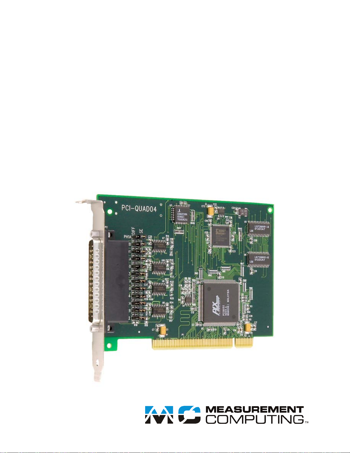
PCI-QUAD04
Chapter 2
Figure 2. PCI-QUAD04
Additional documentation
In addition to this hardware user's guide, you should also receive the Quick Start Guide (available in PDF at
www.mccdaq.com/PDFmanuals/DAQ-Software-Quick-Start.pdf
the software you received with your PCI-QUAD04 and information regarding installation of that software.
Please read this booklet completely before installing any software or hardware.
). This booklet supplies a brief description of
Unpacking the PCI-QUAD04
As with any electronic device, you should take care while handling to avoid damage from static
electricity. Before removing t he PCI-QUAD04 from its packaging, ground yourself using a wrist strap or by
simply touching the computer chassis or other grounded object to eliminate any stored static charge.
If any components are missing or damaged, notify Measurement Computing Corporation immediately by
phone, fax, or e-mail:
Phone: 508-946-5100 and follow the instructions for reaching Tech Support.
Fax: 508-946-9500 to the attention of Tech Support
Email: techsupport@mccdaq.com
8
Page 9

PCI-QUAD04 User's Guide Installing the PCI-QUAD04
Installing the software
Refer to the Quick Start Guide for instructions on installing t he soft ware on the Measurement Computing Data
Acquisition Software CD. This booklet is available in PDF at www.mccdaq.com/PDFmanuals/DAQ-Software-
Quick-Start.pdf.
Configuring the PCI-QUAD04
Before installing the board, configure the channel input mo de for either s ingle-ended or differential. You set the
channel configuration with a set of jumper blocks on the board. Each jumper is labeled for its functionality. By
default, the board is shipped with the channels configured for single-ended operation, with no termination
resistors installed.
Channel input mode
To configure for single -ended operation, place a jumper between pin 2 and pin 3 (labeled SE). To configure for
differential operation, place a jumper between pin 1 (labeled
shown in Figure 3.
DIFF) and pin 2. A single-ended co nfi guration is
Figure 3. Channel input mode configured for SE operation
Input mode jumper settings are listed in the table below.
Channel input mode jumper settings
Input 1 2 3 4
Phase A P3 P8 P14 P11
Phase B P4 P7 P13 P10
Index P5 P6 P12 P9
Input channel
Termination resistors
Although termination resistors typically are not required, SMT pad s on the PCI-QUAD04 are open and labeled
to allow you to install terminating resisto r s from the various inputs to grou nd.
Termination resistor settings
Input 1 2 3 4
Phase A+ R9 R22 R38 R30
Phase A- R10 R23 R39 R31
Phase B+ R11 R20 R36 R28
Phase B- R12 R21 R37 R29
Index+ R14 R19 R35 R27
Index- R13 R18 R34 R26
Channel
9
Page 10

PCI-QUAD04 User's Guide Installing the PCI-QUAD04
Installing the hardware
After configuring the PCI-QUAD04, install the board in your computer. Follow the steps below.
Install the software before you install your board
The driver needed to run t he PCI-QUAD04 is installed with the MCC DAQ software. Therefore, you need to
install the software package you plan to use before you install the hardware.
1. Turn your computer off and open it up.
2. Close your computer and turn it on.
A dialog box opens as the system loads, indicating that new hardware has been detected. If the information
file for this board is not already loaded onto your PC, you are prompted for the disk containing thi s file.
The Measurement Computing Data Acquisition Software CD supplied with your board contains this file. If
required, insert the disk or CD and c lic k
3. To test your i nstallation and configure your bo ard, run the InstaCal utility installe d in the pr evious section.
Refer to the Quick Start Guide that came with your board for information on how to initially set up and
load InstaCal.
OK.
Connecting the board for I/ O operations
Connectors, cables – main I/O connector
The table below lists the board connector type, compatible cables, and compatible accessory products for the
PCI-QUAD04.
Board connectors, cables, and accessory equipment
I/O connector type 37-pin connector
Compatible cables C37F-4X9F-1M
C37FF-x
C37FFS-x
Compatible accessory products CIO-MINI37
CIO-MINI37-VERT
CIO-TERMINAL
SCB-37
Pinout – main I/O connector
Pin assignments of the 37-pin connecto r P2 ar e shown in Figure 4.
Important
Be sure to correctly phase the encoder according to the manufacturer’s instructions.
10
Page 11

PCI-QUAD04 User's Guide Installing the PCI-QUAD04
INDEX2 –
+5V
PHASE2B –
+5VDC
PHASE2A –
+5VDC
PHASE4B –
+5VDC
PHASE4A –
+5VDC
PHASE3B –
+5VDC
PHASE3A –
INDEX1 –
+5VDC
PHASE1B –
+5VDC
PHASE1A –
NO CONNECTION
1
2
3
4
5
6
7
8
9
10
11
12
13
14
15
16
17
18
19
20
21
22
23
24
25
26
27
28
29
30
31
32
33
34
35
36
37
Figure 4. Connector pin out
11
Page 12

PCI-QUAD04 User's Guide Installing the PCI-QUAD04
1
2
3
4
5
20
21
22
23
15
16
17
18
19
34
35
36
37
7
8
9
10
24
25
26
27
28
11
12
13
14
29
30
31
32
33
1
2
3
4
5
6
7
8
9
1
2
3
4
5
6
7
8
9
1
2
3
4
5
6
7
8
9
1
2
3
4
5
6
7
8
9
P1
P2
P3
P4
P5
Phase 1A-
+5VDC
Phase 1B+5VDC
Index 1-
Phase 1A+
Phase 1B+
Ground
Index 1+
Phase 2A-
+5VDC
Phase 2B+5VDC
Index 2-
Phase 2A+
Phase 2B+
Ground
Index 2+
Phase 3A-
+5VDC
Phase 3B+5VDC
Index 3-
Phase 3A+
Phase 3B+
Ground
Index 3+
Phase 4A-
+5VDC
Phase 4B+5VDC
Index 4Phase 4A+
Phase 4B+
Ground
Index 4+
TO PCI-QUAD04 BOARD
Board connector-to-C37F-4X9F-1M cable pinout
Connections from the board connector to the C37F-4X9F-1M cable are shown in Figure 5.
The C37F-4X9F-1M cable can be purchased separately.
Details on the C37F-4X9F-1M cable are available on our web site at
www.mccdaq.com/products/accessories.aspx
Figure 5. Board connector-to-cable C37F-4X9F-1M pinout
.
12
Page 13

PhaseA, PhaseB and Index (+) inputs at user connector routed to (+) inputs of
differential receiver.
PhaseA, PhaseB and Index (+) inputs at user connector routed to (+) inputs of
Meets or exceeds ANSI EIA/TIA-422-B, EIA/TIA-423-B, RS-485.
Designed for multipoint busses on long lines and in noisy environments.
Specifications
Typical for 25 °C unless otherwise specified.
Specifications in italic text are guaranteed by design.
Power consumption
Table 1. Power consumption specifications
Not supplying power to external encoders:
+5 V 325 mA typical, 460 mA max.
Typical supplying 1 Dynamics Research Incremental Optical Rotary Encoder part number M21AAFOBB2E-2500:
+5 V 1058 mA typical, 1479 mA max.
Input
Table 2. Input specifications
Receiver type SN75ALS175 quad differential receiver
Configuration Each channel consists of PhaseA input, PhaseB input and Index input; each
input switch / jumper selectable as single-ended or differential
Differential
differential receiver.
PhaseA, PhaseB and Ind e x (-) inputs at user connector routed to (-) inp ut s of
Chapter 3
Single - ended
Number of channels 4
Common mode input voltage range ±12 V max.
Differential input voltage range ±12 V max.
Input sensitivity ±200 mV
Input hysteresis 50 mV typ.
Input impedance 12 kΩ min.
Propagation delay 27 ns max. (tpLH, tpHL)
Absolute maximum input voltage:
Differential ±14 V max.
Miscellaneous
differential receiver.
PhaseA, PhaseB and Index (-) inputs at user connector routed to ground.
(-) inputs of differential r eceiver routed to +3 V reference.
Meets ITU recommendat ions V.10, V.11, X.26, X. 27.
13
Page 14

PCI-QUAD04 User's Guide Specifications
Counter
Table 3. Counter specifications
Counter type LS7266R1 24-bit Dual-axis Quadrature Counter
Quadrature mode:
Clock frequency 1.2 MHz max .
Separation 100 ns min.
Clock pulse width 400 ns min.
Index pulse width
Count mode:
Clock frequency 30 MHz max, (25 MHz max Mod-N mode)
Clock A - high pulse width 14 ns min.
Clock A - low pulse width 14 ns min.
Filter clock (FCK) 10 MHz
Digital filter rate 10 MHz, software selectable divider (1 to 256 in single steps)
Crystal oscillator (FCK source):
Frequency 10 MHz
Frequency accuracy 100 ppm
300ns min.
Interrupt controll er
Table 4. Interrupt controller specifications
Controller type 8259 Programmable Interrupt Controller
Configuration Polled mode only
Interrupts 2, 3, 5, 7, 10, 11, 12 and 15
Interrupt enable Programmable
Interrupt sources All Carry/Borrow outputs from LS7266R1, all Index inputs
Environmental
Table 5. Environmental specifications
Operating temperature range 0 to 70 °C
Storage temperature range -40 to 100 °C
Humidity 0 to 90 % non-condensing
14
Page 15

Declaration of Conformity
Manufacturer: Measurement Computing Corporation
Address: 10 Commerce Way
Suite 1008
Norton, MA 02766
USA
Category: Electrical equipment for measurement, control and laboratory use.
Measurement Computing Corporation declares under sole responsibility that the product
PCI-QUAD04
to which this declaration relates is in conformity with the relevant provi s ions of the fo llowing standards or other
documents:
EC EMC Directive 2004/108/EC: General Requirements, EN 61326-1:2006 (IEC 61326-1:2005).
Emissions:
EN 55011 (2007) / CISPR 11(2003): Radiated emissions: Group 1, Class A
EN 55011 (2007) / CISPR 11(2003): Conducted emissions: G roup 1, Class A
Immunity: EN 61326-1:2006, Table 3.
IEC 61000-4-2 (2001): Electrostatic Discharge im munity.
IEC 61000-4-3 (2002): Radiated Electromagnetic Field immunity.
IEC 61000-4-4 (2004): Electric Fast Transient Burst Immunity.
IEC 61000-4-5 (2001): Surge Immunity.
IEC 61000-4-6 (2003): Radio Frequency Common Mode Immunity.
IEC 61000-4-11 (2004): Voltage Interrupts.
To maintain compliance to the standar ds of this declaration, the followin g conditions must be met.
The host computer, peripheral equipment, power sources, and expansion hardware must be CE
compliant.
All I/O cables must be shielded, with the shields connected to ground.
I/O cables must be less than 3 meters (9.75 feet) in length.
The host computer must be properly grounded.
Equipment must be operated in a controlled electromagnetic environment as defined by Standards EN
61326-1:2006, or IEC 61326-1:2005.
Declaration of Conformity based on tests conducted by Chomerics Test Services, Woburn, MA 01801, USA in
March, 2009. Test records are outlined in Chomerics Test Report #EMI5299.09.
We hereby declare that the equipment specified conforms to the above Directives and Standards.
Carl Haapaoja, Director of Quality Assurance
Page 16

Measurement Computing Corporation
10 Commerce Way
Suite 1008
Norton, Massachusetts 02766
(508) 946-5100
Fax: (508) 946-9500
E-mail: info@mccdaq.com
www.mccdaq.com
 Loading...