

Page 1

User's Guide
Document Revision 6
© Copyright 2011
PCI-CTR05
9513-Based Counter/Timer
June 2011
Page 2

HM PCI-CTR05.doc
Your new Measurement Computing product comes with a fantastic extra –
Management committed to your satisfaction!
Refer to www.mccdaq.com/execteam.html for the names, titles, and contact information of each key executive at Measurement
Computing.
Thank you for choosing a Measurement Computing product – and congratulations! You own the finest, and you can now enjoy
the protection of the most comprehensive warranties and unmatched phone tech support. It’s the embodiment of our mission:
To provide data acquisition hardware and software that will save time and save money.
Simple installations minimize the time between setting up your system and actually making measurements. We offer quick and
simple access to outstanding live FREE technical support to help integrate MCC products into a DAQ system.
Limited Lifetime Warranty: Most MCC products are covered by a limited lifetime warranty against defects in materials or
workmanship for the life of the product, to the original purchaser, unless otherwise noted. Any products found to be defective in
material or workmanship will be repaired, replaced with same or similar device, or refunded at MCC’s discretion. For specific
information, please refer to the terms and conditions of sale.
Harsh Environment Warranty® Program: Any Measurement Computing product that is damaged due to misuse, or any
reason, may be eligible for replacement with the same or similar device for 50% of the current list price. I/O boards face some
harsh environments, some harsher than the boards are designed to withstand. Contact MCC to determine your product’s
eligibility for this program
30 Day Money-Back Guarantee: Any Measurement Computing Corporation product may be returned within 30 days of
purchase for a full refund of the price paid for the product being returned. If you are not satisfied, or chose the wrong product by
mistake, you do not have to keep it.
These warranties are in lieu of all other warranties, expressed or implied, including any implied warranty of merchantability or
fitness for a particular application. The remedies provided herein are the buyer’s sole and exclusive remedies. Neither
Measurement Computing Corporation, nor its employees shall be liable for any direct or indirect, special, incidental or
consequential damage arising from the use of its products, even if Measurement Computing Corporation has been notified in
advance of the possibility of such damages.
Trademark and Copyright Inform ation
Measurement Computing Corporation, InstaCal, Universal Library, and the Measurement Computing logo are either trademarks
or registered trademarks of Measurement Computing Corporation. Refer to the Copyrights & Trademarks section on
mccdaq.com/legal
mentioned herein are trademarks or trade names of their respective companies.
© 2011 Measurement Computing Corporation. All rights reserved. No part of this publication may be reproduced, stored in a
retrieval system, or transmitted, in any form by any means, electronic, mechanical, by photocopying, recording, or otherwise
without the prior written permission of Measurement Computing Corporation.
Notice
Measurement Comput i ng Corporation does not aut horize any Measurement Computing Corporat ion product for use
in life support systems and/or devices without prior written consent from Measurement Computing Corporation.
Life support devices/systems are devices or systems that, a) are intended for surgical implantation into the body, or
b) support or sustain life and whose failure to perform can be reasonably expected to result in injury. Measurement
Computing Corporation products are not designed with the components required, and are not subject to the testing
required to ensure a level of reliability suitable for the treatment and diagnosis of people.
for more information about Measurement Computing trademarks. Other product and company names
2
Page 3

Table of Contents
Preface
About this User's Guide ....................................................................................................................... 4
What you will learn from this user's guide ......................................................................................................... 4
Conventions in this user's guide ......................................................................................................................... 4
Where to find more information ......................................................................................................................... 4
Chapter 1
Introducing the PCI-CTR05 .................................................................................................................. 5
PCI-CTR05 block diagram m ............................................................................................................................. 6
Chapter 2
Installing the PCI-CTR05 ...................................................................................................................... 7
What comes with your shipment? ....................................................................................................................... 7
Hardware .......................................................................................................................................................................... 7
Documentation .................................................................................................................................................................. 7
Optional components ........................................................................................................................................................ 7
Unpacking ........................................................................................................................................................... 8
Installing the software ........................................................................................................................................ 8
Installing the hardware ....................................................................................................................................... 8
Connecting the board fo r I / O operations ............................................................................................................ 9
Pinout – main I/O connector ............................................................................................................................................10
Field wiring, signal termination and conditioning ...........................................................................................................11
Mechanical drawing ......................................................................................................................................... 12
Chapter 3
Specifications ...................................................................................................................................... 13
Digital input / output ......................................................................................................................................... 13
Interrupt ............................................................................................................................................................ 13
Counter ............................................................................................................................................................. 13
Power consumption .......................................................................................................................................... 15
Environmental .................................................................................................................................................. 15
Mechanical ....................................................................................................................................................... 15
Main connector and pin out .............................................................................................................................. 15
J1 pin out .......................................................................................................................................................... 16
Declaration of Conformity .................................................................................................................. 17
3
Page 4

About this User's Guide
What you will learn from this user's guide
This user's guide explains how to install, configure, and use the PCI-CTR05 so that you get the most out of its
counter features. This user's guide also refers you to related documents available on our web site, and to
technical support resources.
Conventions in this user's guide
For more information about …
Text presented in a box signifies additional information and helpful hints related to the subject matter you are
reading.
Caution! Shaded caution state ments present information to help you avoid injuring yourself and others,
damaging your hardware, or losing your data.
bold text Bold text is used for the names of objects on a screen, such as buttons, text boxes, and check boxes.
Preface
italic text Italic text is used for the names of manuals and help topic titles, and to emphasize a word or phrase.
Where to find more information
Additional information about PCI-CTR05 hardware is available on our website at www.mccdaq.com. You can
also contact Measurement Computing Corporation by phone, fax, or email with specific questions.
Phone: 508-946-5100 and follow the instructions for reaching Tech Support.
Fax: 508-946-9500 to the attention of Tech Support
Email: techsupport@mccdaq.com
We recommend that you use the Universal Library for controlling your board. Only experienced programmers
should attempt register level-programming. If you must use register-level programming in your application,
refer to the Register Map for the PCI-CTR05. This document is available on our web site at
www.mccdaq.com/registermaps/RegMapPCI-CTR05.pdf
.
4
Page 5

Chapter 1
Introducing the PCI-CTR05
The PCI-CTR05 is a high-performance, low-cost counter/timer boa rd for PCI bus-compatible computers.
The PCI-CTR05 is based on the 9513 counter/tim e r devi c e . The PCI-CTR05 has one 9513 counter/timer device.
The 9513 device has five independent 16-bit counters (65,536 counts). Each counter has an input source, count
register, load register, hold register, alarm register, output, and gate associated with each counter.
The 9513 is software-programmable for event counting, pulse and frequency measurement, alarm comparisons,
and other input functions. The 9513 can generate frequencies with either complex duty cycles, or with one-shot
and continuous-output modes. You can chain up to five 9513 counters together using software to enable a 32-,
48-, 64-, or 80-bit counter that does not require hardware connections. The gate source and gating functions are
software-selectable.
An eight-bit, high-current digital output port provides logic-level control, and can be used to switch solid state
relays. An eight-bit digital input port can be used to sense contact closures and other TTL level signals. The
PCI-CTR05 also provides access to the PCI bus interrupt assigned to the board.
Depending on the revision of your PCI-CTR05, it may support both 3.3 V and 5 V PCI signaling environments,
or only 5 V PCI signaling environments. Refer to Installing the hardware
signaling environments your board supports.
to learn how to determine the PCI
For more information on the 9513 counter/timer, refer to the 9513 data sheet. This document is available at
www.mccdaq.com/PDFs/Manuals/9513A.pdf
.
5
Page 6
PCI-CTR05 User's Guide Introducing the PCI-CTR05
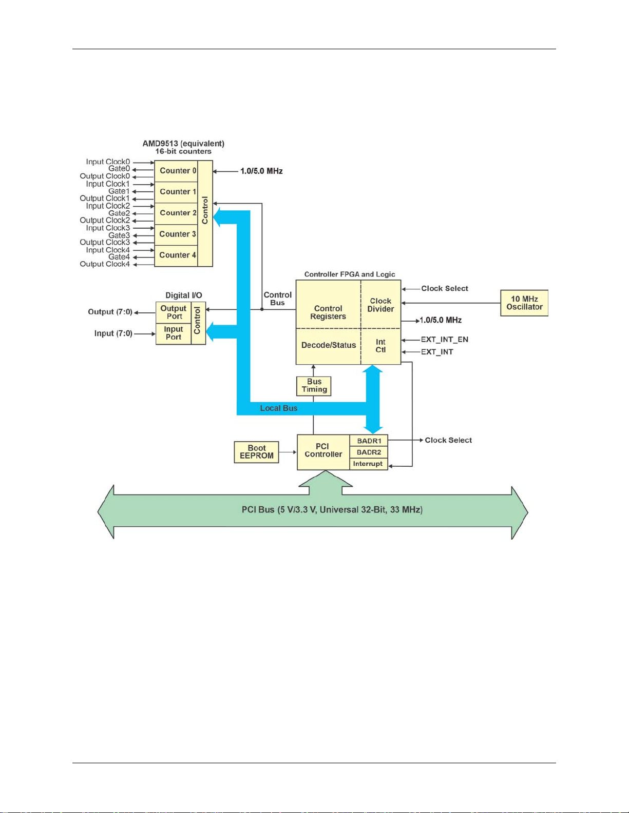
PCI-CTR05 block diagram m
PCI-CTR05 functions are illustrated in the block diagram shown here
Figure 1. PCI-CTR05 functional block diagram
6
Page 7

Installing the PCI-CTR05
What comes with your shipment?
As you unpack your board, make sure that the following components are included.
Hardware
PCI-CTR05
Chapter 2
Documentation
In addition to this hardware user's guide, a Quick Start Guide booklet is in cluded with the PCI-CTR05
shipment. This booklet provides an overview of the MCC DAQ software you received with the device, and
includes information about installing the software. Please read this booklet completely before installing any
software or hardware.
Optional components
Cables
C37FF-x
Signal termination and conditioning accessories
MCC provides signal termination and signal conditioning products for use with the PCI-CTR05. Refer to
Field wiring, signal termination and conditioning
C37FFS-x
for a complete list of compatible accessory products.
7
Page 8

PCI-CTR05 User's Guide Installing the PCI-CTR05
Unpacking
As with any electronic device, take care while handling to avoid damage from static electricity. Before
removing thePCI-CTR05 from its packaging, ground yourself using a wrist strap or by simply touching the
computer chassis or other grounded object to eliminate any stored static charge.
If the device is damaged, notify Measurement Computing Corporation immediately by phone, fax, or e-mail.
Phone: 508-946-5100 and follow the instructions for reaching Tech Support.
Fax: 508-946-9500 to the attention of Tech Support
Email: techsupport@mccdaq.com
For international customers, contact your local distributor. Refer to the "International Distributors" section on
our web site at www.mccdaq.com/contact2.aspx
.
Installing the software
Install Universal Li brary and InstaCal when you want to develop data acquisition applications using Windows
programming languages. Universal Library and InstaCal software are included on the CD that ships with the
board.
Refer to the Quick Start Guide for instructions on installing the software on the Measurement Computing Data
Acquisition Software CD. This booklet is available in PDF at www.mccdaq.com/PDFs/Manuals/DAQ-
Software-Quick-Start.pdf
Installing the hardware
The PCI-CTR05 board is completely plug-and-play. There are no switches or jumpers to set on the board.
Configuration is controlled by your system's BIOS.
Examine your board to determine it supports 3.3 V signaling environments
Before you install the board, examine it to determine if it supports both 3.3 V and 5 V PCI signaling
environments.
If the board has two notches on its PCI connector, it supports both 3.3 V or 5 V PCI signaling environments.
Supports both 3.3 V and 5 V PCI signaling environments
If the board has one notch on the PCI connector, it supports only 5 V PCI signaling environments.
Hardware specificat i ons f o r this version of the board are available on our web site at
www.mccdaq.com/PDFs/specs/PCI-CTR05r2_spec2-spec.pdf.
Supports only 5 V PCI signaling environments
8
Page 9

PCI-CTR05 User's Guide Installing the PCI-CTR05
To install your board, follow the steps below.
Install the software before you install your board
The driver needed to run the PCI-CTR05 is installed when you install the software. Therefore, you need to
install the software before you install the hardware.
1. Power off and unplug the computer, and remove the cover to expose the expansion slots.
2. Touch any metal part of the computer to discharge static electricity. Static electricity can damage the board.
3. Insert your board into an available PCI slot.
4. Close your computer and turn it on.
A dialog box opens as the system loads, indicating that new hardware has been detected. The information
file for this board should have already been loaded onto your PC when you installed the software CD
supplied with your board, and should be detected automatically by Windows. If you have not installed this
software, cancel the dialog, install the software, and restart your computer.
5. Run InstaCal to test your installation and to configure the board. Refer to the Quick Start Guide that came
with your board for information on how to initially set up InstaCal.
Allow your computer to warm up for at least 15 minutes before acquiring data. The high speed components
used on the board generate heat, and it takes this amount of time for a board to reach steady state if it has been
powered off for a significant amount of time.
Connecting the board for I/O operati ons
The table below lists the board connectors, applicable cables and compatible accessory boards.
Board connectors, cables, accessory equipment
Connector type 37-pin shielded D-type, right angle (J1 – see Figure 2)
Compatible cables C37FF-x, unshielded ribbon cable (Figure 3)
C37FFS-x, shielded round cable (Figure 4)
Compatible accessory
products
CIO-MINI37
CIO-MINI37-VERT
CIO-TERMINAL
SCB-37
9
Page 10

PCI-CTR05 User's Guide Installing the PCI-CTR05
CTR1GATE
CTR1CLK
CTR1OUT
CTR2OUT
CTR3OUT
CTR4OUT
CTR5OUT
OSC OUT
DIN0
DIN1
DIN2
DIN3
DIN4
DIN5
DIN6
DIN7
PC +5V
J1
CTR2CLK
CTR2GATE
CTR3CLK
CTR3GATE
CTR4CLK
CTR4GATE
CTR5CLK
CTR5GATE
GND
D 0 OUT
D 1 OUT
D 2 OUT
D 3 OUT
D 4 OUT
DOUT7
DOUT6
DOUT5
IRQ INPUT
IRQ ENABLE
20
21
22
23
24
25
26
27
28
29
30
31
32
33
34
35
36
37
1
2
3
4
5
6
7
8
9
10
11
12
13
14
15
16
17
18
19
Pinout – main I/O connector
The board connector is a male, 37-pin D-type connector (J1). Digital input, digital output, interrupt, and signals
from the 9513 are all accessible on this connector.
Figure 2. Board connector J1
Information on signal connections
For general information regarding digital I/O techniques, including signal conditioning and low pass filters,
refer to the Guide to Signal Connections. This document is available on our web site at
www.mccdaq.com/pdfs/signals.pdf).
10
Page 11

PCI-CTR05 User's Guide Installing the PCI-CTR05
20
1
37
19
20
1
37
19
The red stripe
identifies pin # 1
20
1
37
19
20
1
37
19
Figure 3. C37FF-x cable
Figure 4. C37FFS-x cable
Field wiring, signal termination and conditioning
You can use the following MCC screw terminal boards with the PCI-CTR05 board using the C37FF-x or
C37FFS-x cable.
SCB37 — 37-conductor, shielded signal connection/screw terminal box that provides two independent 37-
pin connections.
CIO-MINI37 — 4 x 4, 37-pin screw terminal board.
CIO-MINI37-VERT — 37-pin screw terminal accessory with vertical 37-pin male D connector.
CIO-TERMINAL — 16 X 4 universal screw terminal board with on-board prototype area and circuitry.
Details on these products are available on our web site.
11
Page 12

PCI-CTR05 User's Guide Installing the PCI-CTR05
Mechanical drawing
Figure 5. PCI-CTR05 circuit board dimensi ons
12
Page 13

Specifications
All specifications are subject to change without notice.
Typical for 25 °C unless otherwise speci fied.
Specifications in italic text are guaranteed by design.
Digital input / output
Table 1. Digital I/O specifications
Digital type Discrete, 5 V/TTL compatible
Output: 74ACT273
Input: 74LS373
Number of I/O 8 input, 8 output
Configuration 1 bank of 8 as output, 1 bank of 8 as strobed input
Input high voltage 2.0 V min, 7.0 V absolute max
Input low voltage 0.8 V max, –0.5 V absolute min
Output high voltage 3.94 V min @ -24 mA (Vcc = 4.5 V)
Output low voltage 0.36 V max @ 24 mA (Vcc = 4.5 V)
Data transfer Programmed I/O
Power-up / reset state Digital outputs reset to TTL low
Digital input strobe
Digital input strobe pulse width
high/low
Data setup to digital input strobe 5 ns min
Data hold from digital input strobe 20 ns min
Active low latch enable input, internally pulled high through 10 KΩ resistor
15 ns min
Chapter 3
Interrupt
Table 2. Interrupt specification s
Number of user interrupts 1
PCI interrupt PCI INTA# - mapped to IRQn via PCI BIOS at boot-time
Interrupt enables
Interrupt sources External: IRQ IN, polarity programmable through PCI9030-AA60PI.
External: IRQ ENABLE, active low, disabled by default through internal resistor to
TTL high and programmable through PCI9030-AA60PI.
0 = disabled
1 = enabled (default)
1 = active high
0 = active low (default)
IRQ IN maps to PLX 9030 LINT1.
Counter
Refer to the CTS9513-2 data sheet for complete 9513 specifications and operating modes. The SAVE command
for the CTS9513 device does not behave predictably when using clocks which are not synchronous with the
logic timing. The CTS9513-2 data sheet is available on our web site at
www.mccdaq.com/PDFs/Manuals/9513A.pdf
.
13
Page 14

PCI-CTR05 User's Guide Specifications
X2 clock frequency scaler
No gating.
On or low impedance to ground.
Input high voltage
2.2 V min, Vcc max
Table 3. Counter specifications
Parameter Conditions
Counter type 9513
Configuration One 9513 device. Five up/down counters, 16-bits each.
Compatibility 5V/TTL
The 9513 device is programmable for:
Clock source Software selectable:
External:
Counter 1-5 clock inputs
Counter 1-5 gate inputs
Internal:
Terminal count of previous counter
Gate: Software selectable source:
External (default logic high):
Active high or low level or edge, counter 1 – 5 gate input
Active high level previous gate or next gate
All external gate signals (CTRxGATE) individually pulled up through
10 KΩ resistors to +5 V.
Internal:
Active high previous counter terminal count
Output: Software selectable:
Always low
High pulse on terminal count
Low pulse on terminal count
Toggle on terminal count
Inactive, high impedance at user connector counter # output.
Osc Out Software selectable source:
Counter # input
Gate # input
Prescaled clock source (X2 clock frequency scaler)
Software selectable divider:
Division by 1-16
Software selectable enable:
Clock input frequency 6.8 MHz max (145 ns min period)
X2 clock input sources Software selectable:
1.0 MHz (10 MHz Xtal divided by 10)
5.0 MHz (10 MHz Xtal divided by 2)
X2 clock frequency scaler
High pulse width (clock input) 70 ns min
Low pulse width (clock input) 70 ns min
Gate width high 145 ns min
Gate width low 145 ns min
Input low voltage -0.5 V to 0.8 V max
BCD scaling (X2 divided by 10, 100, 1000 or 10000) or binary scaling
(X2 divided by 16, 256, 4096 or 65536)
Output low voltage @ IIl=3.2 mA 0.4 V max
Output high voltage @ IIH= -200 uA 2.4 V min
Crystal oscillator frequency 10 MHz
Frequency accuracy 50 ppm
14
Page 15

PCI-CTR05 User's Guide Specifications
C37FFS-x, shielded round cable
Power consumption
Table 4. Power consumption specifi cations
+5 V
+5 V available at connector 1 A max
307 mA typ, 549 mA max. Does not include power consumed through the I/O
connector.
Environmental
Table 5. Environmental specifications
Operating temperature range
Storage temperature range
Humidity
0 °C to 55 °C
-20 °C to 70 °C
0% to 90% non-condensing
Mechanical
Table 6. Mechanical specifications
Dimensions (L × W × H) 132.3 × 106.7 × 11.7 mm (5.2 × 4.2 × 0.5 in.)
Form factor
Universal PCI keying. Compatible with either 3.3 V or 5 V PCI signaling
environments.
Main connector and pin out
Main connector J1 is compatible with the CIO-CTR05 and the CIO-CTR10.
Table 7. Main connector specifications
Connector type 37 pin shielded D-type, right angle
Compatible cables
Compatible accessory products CIO-MINI37
C37FF-x, unshielded ribbon cable
CIO-MINI37-VERT
CIO-TERMINAL
SCB-37
15
Page 16

PCI-CTR05 User's Guide Specifications
Pin
Signal Name
1
IRQ INPUT
2
IRQ ENABLE
3
DOUT7
4
DOUT6
6
DOUT4
8
DOUT2
9
DOUT1
10
DOUT0
11
GND
12
CTR5GATE
13
CTR5CLK
15
CTR4CLK
17
CTR3CLK
18
CTR2GATE
19
CTR2CLK
20
PC +5V
21
DIN STROBE
22
DIN7
23
DIN6
24
DIN5
26
DIN3
28
DIN1
29
DIN0
30
OSC OUT
31
CTR5OUT
32
CTR4OUT
33
CTR3OUT
35
CTR1OUT
37
CTR1GATE
J1 pin out
Table 8. Main connector J1 pin out
5 DOUT5
7 DOUT3
14 CTR4GATE
16 CTR3GATE
25 DIN4
27 DIN2
34 CTR2OUT
36 CTR1CLK
16
Page 17

Declaration of Conformity
Manufacturer: Measurement Computing Corporation
Address: 10 Commerce Way
Suite 1008
Nor ton, MA 02766
USA
Category: Electrical equipment for measurement, control and laboratory use.
Measurement Computing Corporation declares under sole responsibility that the product
PCI-CTR05
EU EMC Directive 89/336/EEC: Electromagnetic Compatibility, EN55022 (1995), EN55024 (1998)
Emissions: Group 1, Class B
EN55022 (1995): Radiated and Conducted emissions.
Immunity: EN55024
EN61000-4-2 (1995): Electrostatic Discharge immunity, Criteria A.
EN61000-4-3 (1997): Radiated Electromagnetic Field immunity Criteria A.
EN61000-4-4 (1995): Electric Fast Transient Burst immunity Criteria A.
EN61000-4-5 (1995): Surge immunity Criteria A.
EN61000-4-6 (1996): Radio Frequency Common Mode immunity Criteria A.
EN61000-4-8 (1994): Power Frequency Magnetic Field immunity Criteria A.
EN61000-4-11 (1994): Voltage Dip and Interrupt immunity Criteria A.
Declaration of Conformity based on tests conducted by Chomerics Test Services, Woburn, MA 01801, USA in
September, 2001. Test records are outlined in Chomerics Test Report #EMI3053.01.
We hereby declare that the equipment specified conforms to the above Directives and Standards.
Carl Haapaoja, Director of Quality Assurance
Page 18

Measurement Computing Cor poration
10 Commerce Way
Suite 1008
Norton, Massachusetts 02766
(508) 946-5100
Fax: (508) 946-9500
E-mail: info@mccdaq.com
www.mccdaq.com
 Loading...