

Page 1
Net232TM
Ethernet/RS-232 Converter
for MultiScan, TempScan, and ChartScan Applications
the smart approach to instrumentation
IOtech, Inc.
25971 Cannon Road
Cleveland, OH 44146-1833
Phone: (440) 439-4091
Fax: (440) 439-4093
E-mail: sales@iotech.com
Internet: www.iotech.com
TM
Net232 User’s Guide
p/n
1037-0901
Released per EO # 2118Rx February, 1999
rev
2.0
Page 2
Warranty Information
Your IOtech warranty is as stated on the product warranty card. You may contact IOtech by phone,
fax machine, or e-mail in regard to warranty-related issues.
Phone: (440) 439-4091, fax: (440) 439-4093, e-mail: sales@iotech.com
Limitation of Liability
IOtech, Inc. cannot be held liable for any damages resulting from the use or misuse of this product.
Copyright, Trademark, and Licensing Notice
All IOtech documentation, software, and hardware are copyright with all rights reserved. No part of this
product may be copied, reproduced or transmitted by any mechanical, photographic, electronic, or other
method without IOtech’s prior written consent. IOtech product names are trademarked; other product
names, as applicable, are trademarks of their respective holders. All supplied IOtech software (including
miscellaneous support files, drivers, and sample programs) may only be used on one installation. You may
make archival backup copies.
FCC Statement
IOtech devices emit radio frequency energy in levels compliant with Federal Communications Commission
rules (Part 15) for Class A devices. If necessary, refer to the FCC booklet
Radio-TV Interference Problems (stock # 004-000-00345-4) which is available from the U.S. Government
Printing Office, Washington, D.C. 20402.
How To Identify and Resolve
CE Notice
Many IOtech products carry the CE marker indicating they comply with the safety and emissions
standards of the European Community. As applicable, we ship these products with a Declaration of
Conformity stating which specifications and operating conditions apply.
Warnings and Cautions
Refer all service to qualified personnel. This caution symbol warns of possible personal injury or
equipment damage under noted conditions. Follow all safety standards of professional practice and the
recommendations in this manual. Using this equipment in ways other than described in this manual can
present serious safety hazards or cause equipment damage.
This warning symbol is used in this manual or on the equipment to warn of possible injury or death
from electrical shock under noted conditions.
This ESD caution symbol urges proper handling of equipment or components sensitive to damage from
electrostatic discharge. Proper handling guidelines include the use of grounded anti-static mats and
wrist straps, ESD-protective bags and cartons, and related procedures.
Specifications and Calibration
Specifications are subject to change without notice. Significant changes will be addressed in an addendum
or revision to the manual. As applicable, IOtech calibrates its hardware to published specifications.
Periodic hardware calibration is not covered under the warranty and must be performed by qualified
personnel as specified in this manual. Improper calibration procedures may void the warranty.
Quality Notice
IOtech has maintained ISO 9001 certification since 1996. Prior to shipment, we thoroughly test our
products and review our documentation to assure the highest quality in all aspects. In a spirit of
continuous improvement, IOtech welcomes your suggestions.
2 Net232 User’s Guide,
1037-0901, rev 2.0
Page 3
Contents
Overview ……3
Check Your Order…… 3
Install Software…… 4
Configure Net232’s Address Settings ……4
Configure Acquisition Device for RS-232 Serial Communications …… 6
Connect Net232 to the Acquisition Device ……7
Identify Your Network Scenario ……7
Make Ethernet Connections ……9
Ethernet API Reference ……11
Specifications ……16
Overview
Point-to Point (Non-Network) Setup…… 7
Private LAN Setup …… 8
Private LAN Setup with Multiple Networks……8
LAN Setup with Internet Access ……9
Net232 provides a means of connecting ChartScan, TempScan, and MultiScan data acquisition devices to
the ethernet. This guide will show you how to configure your Net232’s address, connect the Net232 to your
acquisition device, identify the four basic network scenarios, and connect your system to the ethernet. The
final page of this document includes Net232 product specifications.
For successful Net232 operations, your computer needs to have the following:
•
•
•
•
•
•
Although this guide provides instructions for connecting the acquisition device to the ethernet,
you may need to refer to your device user’s manual for additional instructions, such as DIP
switch configuration for RS-232 serial communications.
Check Your Order
If you have not already done so, carefully unpack your shipping carton and check all contents for damage which may
have occurred during shipment. Immediately report all damage to the shipping agent and your sales representative.
Retain all shipping materials in case the unit must be returned to the factory.
The Net232 package should contain the following, depending on your order:
Net232 Ethernet/RS-232 Converter
483-0601
1035-0971
1037-0901 Net232 User’s Guide
TR-2 Power Supply
CA-192-5 10BASE-T “straight through” ethernet cable, 5 ft.
CA-192-Adapter 10BASE-T “cross-over” adapter
10BASE-T Ethernet card
Available COMM Port
PC system with Pentium processor
Windows 3.1+, Windows 95, or Windows 98
At least 8 Mbytes of RAM for Windows 3.1+ (16 Mbytes recommended)
At leasr 16 Mbytes of Ram for Windows95/98 (32 Mbytes recommended)
ChartView Software
ChartViewNET Registration ID Sheet
Net232 User’s Guide,
1037-0901, rev 2.0
3
Page 4
Install Software
Use Microsoft Windows Run dialog box to configure Net232’s address and install the ChartView program group.
Direct Windows to run the SETUP.EXE file found on Installation Diskette 1 (or CD-ROM, if applicable). Follow the
on-screen
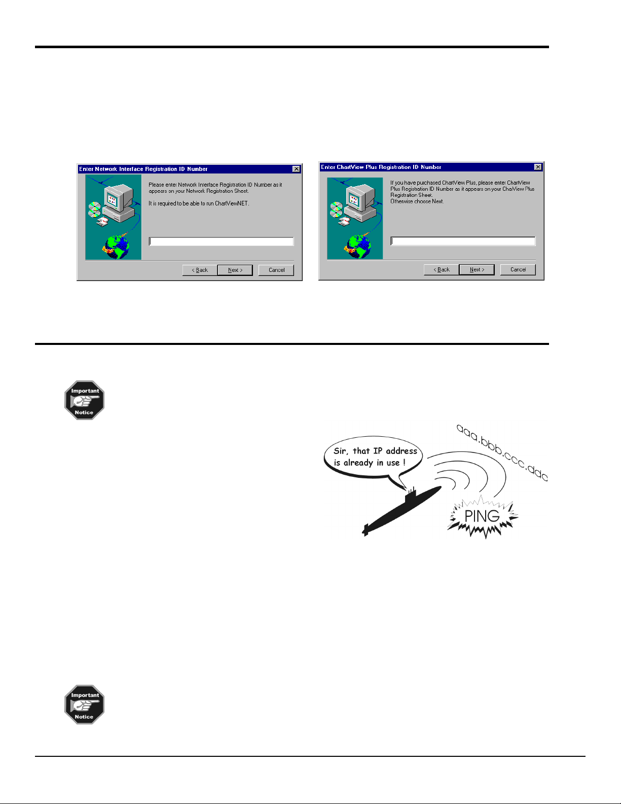
Early in the setup you will be prompted to enter your Registration ID Number. This number appears on your Network
Registration Sheet (1035-0971) and must be entered to enable ChartViewNET.
If you ordered ChartView Plus, enter the registration ID number as it appears on your ChartView Plus Registration
Sheet (1035-0970). Otherwise, press Next and continue to follow the screen prompts.
dialog boxes to complete a successful installation.
Screen Prompt for Entering the Registration ID Number Screen Prompt for Entering the ChartView Plus ID Number
Configure Net232’s Address Settings
Prior to configuring the Net232 and connecting it to your network, use the PING utility (provided
by Windows
another device.
Example:
For a given address: aaa.bbb.ccc.ddd, enter as follows from
the DOS prompt:
C:> PING aaa.bbb.ccc.ddd
If no other device is using the address, the PING utility will
report a “device time out” and a 100% loss of data. Any
other response indicates that a device on the network is
already using the IP address, and that you will need to use
another address.
Using the NetScan Configuration Utility
Net232 must be configured before putting it to use. Configuration is accomplished through the NetScan Configuration
Utility. The utility installs after you select “Net232” as your device type.
You can access the NetScan Configuration Utility from Window’s desktop Start Menu, as follows:
Start ⇒⇒⇒⇒ Programs ⇒⇒⇒⇒ ChartView ⇒⇒⇒⇒ Interface Configuration
The utility’s window displays a “welcome” prior to prompting you through the required configuration steps. The
following steps appear in the utility’s screen prompts. Note that each “step” has a corresponding tab (see following
figure).
TM
). The PING utility will inform you if your intended address is already in use by
The network interface must be properly configured before Net232 can communicate with a
computer via the ethernet.
4 Net232 User’s Guide,
1037-0901, rev 2.0
Page 5
Step 1
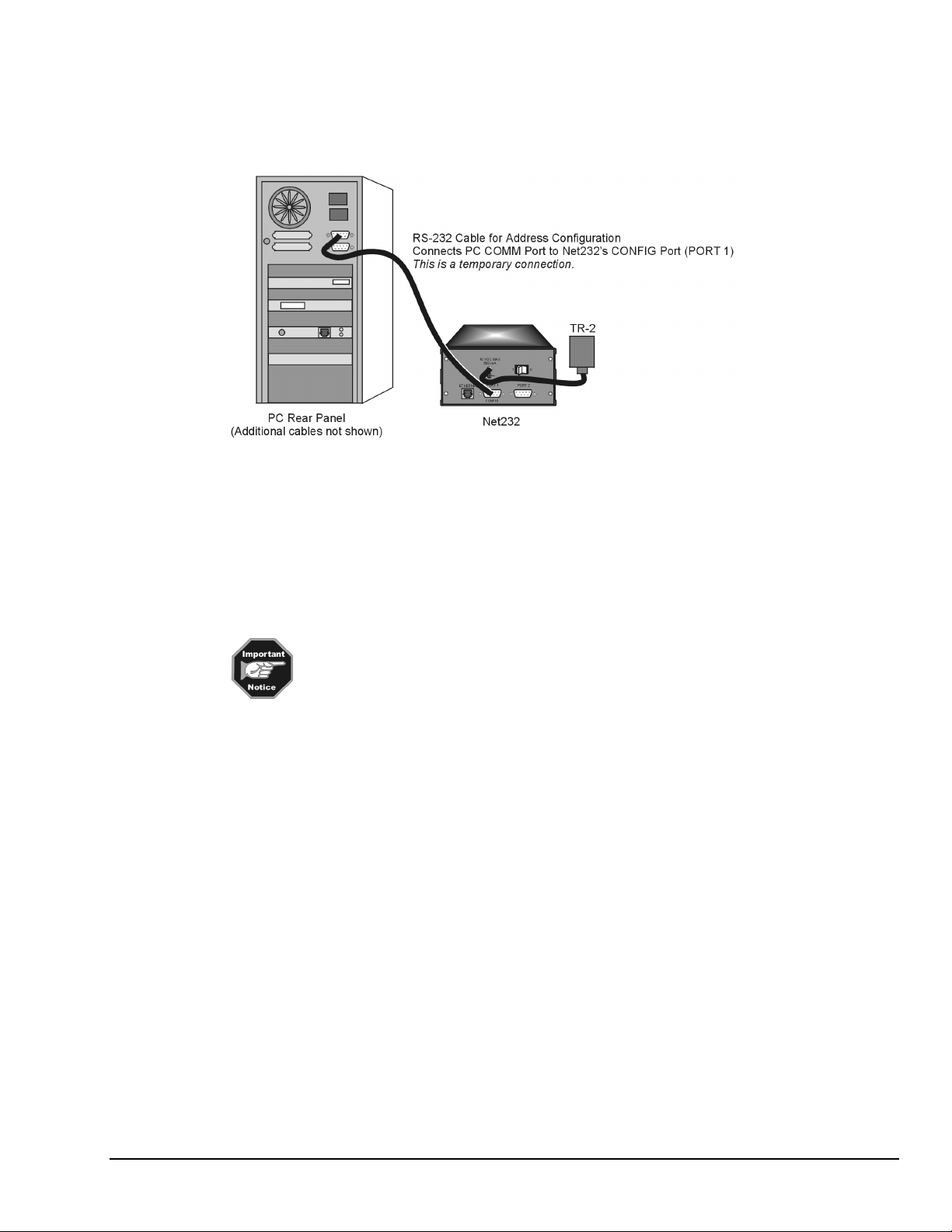
a) Connect an RS-232 serial cable to an available serial communication port (COMM Port) on your
computer. Note that CA-47 cables cn connect to 25 pin COMM ports or 9 pin COMM ports.
b) Connect the other end of the RS-232 cable to Net232’s CONFIG port (PORT 1).
COMM Port Connections for Configuring Net232’s Address Settings
Step 2
a) Cycle Net232’s power switch “Off,” then “On.”
b) In the NetScan Configuration Utility, check (3) the on-screen box that states, “I have performed the
actions described above.”
Step 3
Basic information regarding TCP/IP Addressing for Net232 is presented below. If you
have any difficulty regarding address settings, please contact your network
administrator.
a) Review the following terminology as needed, then proceed to step 3b.
Protocol
The Net232 uses TCP/IP (Transport Control Protocol/Internet Protocol) for communications over the
ethernet. You can access Net232-connected devices from virtually anywhere in the world since the World
Wide Web uses this same protocol.
TCP/IP addressing consists of three parameters: the IP address, the Sub-net Mask, and the Gateway
Address. Each of these parameters consists of four different numbers which range from 0 to 255. The
numbers are typically represented in a dotted decimal format, for example: 192.88.247.11.
IP Address
The IP (Internet Protocol) address is unique to one specific device on the network, and can not be shared by
any other device on the network. The only restrictions on the IP address are:
1) the first number must be between 127 and 255
2) the last number must be between 1 and 254.
Sub-net Mask
The Sub-net Mask determines how many addresses are on the network. Note that Class C networks consist
of up to 256 addresses; and are quite common. For a Class C Network the
255.255.255.0. All computers on the network must have the same
subnet mask
Sub-net Mask
.
would be
Net232 User’s Guide,
1037-0901, rev 2.0
5
Page 6

Gateway Address
A gateway address is needed to a access a device (gateway, or router) that can route traffic from one
network to another. The gateway address is the actual address of the gateway (router) device.
b) If necessary, make changes to the address settings, then press the Apply Changes button. You may
need contact your network administrator.
c) Press the Next button (see following figure).
NetScan Configuration Utility, Step 3
You will receive a “>>Communications Error<<” if the NetScan Configuration Utility
fails to communicate with your setup. Likely causes are:
1) Wrong COMM Port selected in the utility (step1).
2) Serial cable connected to wrong connector on Net232, PC, or both.
If you received the error message, check system cable connections, correct the problem,
then return to Step 2 and perform the requested actions.
Finished
a) Exit the NetScan Configuration Utility.
b) Cycle Net232’s power switch “Off” and “On.”
c) Disconnect the RS-232 cable from Net232’s CONFIG port (PORT 1). Remove the other end of the
cable from your PC’s COMM port.
Configure Acquisition Device for RS-232 Communications
ChartScan, TempScan, and MultiScan units have a DIP switch located on the unit’s rear panel. Prior to
connecting Net232 to your data acquisition device, refer to your device user’s manual to ensure the unit is
configured for RS-232 operation.
Refer to your acquistion device user’s manual to ensure proper RS-232 configuration.
6 Net232 User’s Guide,
1037-0901, rev 2.0
Page 7

Connect Net232 to the Acquisition Device
The rear panels of ChartScan, TempScan, and MultiScan have an RS-232/422 nine pin (DB9) connector. Connect
Net232 to your acquisition device as follows:
1. Connect the a CA-47 cable (or equivalent DB9 cable) to Net232’s PORT 2 (see note).
2. Connect the other end of the cable to your acquisition device’s 9-pin RS-232/422 connector.
RS-232 Connection of Net232’s PORT 2 to the Acquisition Device
The Network Interface Settings dialog box (accessed through ChartView’s Device pull-down
menu) allows you to select PORT 1 or PORT 2 for your acquisition device. PORT 2 is the
default. For this reason the acquisition device should be connected to Net232’s PORT 2. A
second device can be connected to Net232 (through PORT 1).
You can only communicate with one Net232-connected device at a time.
Identify your Network Scenario
There are four basic network scenarios that pertain to Net232 ethernet operation. Note that proper TCP/IP
configuration is extremely important, and you must obtain TCP/IP addressing parameters before
configuring the protocol. The rules for configuration differ for each scenario as follows:
1) Point-to-Point (Non-Network) Setup
Point-to-Point Setup
In the
Point-to-Point
cross-over adapter (CA-192-Adapter).
Since there is no actual network the only requirements are:
1) The first three numbers of Net232’s IP address must match the first three numbers of the network’s
interface IP address (as specified in ChartView).
2) The sub-net mask should be set to 255.255.255.0
3) The gateway address can be omitted.
scenario, Net232 is connected directly to a PC using a 10BASE-T cable and
Example
TPC/IP address set to 192.88.247.1
Sub-net mask
* Acquisition Device refers to ChartScan, TempScan, or MultiScan. Two of these devices (in any
Net232 User’s Guide,
set to 255.255.255.0
combination) can be connected to the Net232 via PORT 1 and PORT 2.
1037-0901, rev 2.0
7
Page 8

2) Private Local Area Network (LAN) Setup
Private LAN Setup
In this simple LAN scenario, Net232 is connected to a network with several PC’s using the TCP/IP
protocol. These networks typically use a system administrator or network analyst to address TCP/IP issues.
For private LAN setups, requirements are:
1) A unique IP address must be assigned to the Net232 device
2) The first three numbers of the IP address must be the same for all devices on the network
3) The sub-net mask should be set to 255.255.255.0
4) The gateway address can be omitted
Example
TPC/IP address set to 192.88.247.1 for Net232 device
First three numbers of all network devices are 192.88.247
Sub-net mask
is set to 255.255.255.0
3) Private LAN Setup with Multiple Networks
Private LAN with Multiple Networks
In multiple-network scenarios, two or more networks connect to a common gateway via ethernet hubs. In
regard to multiple networks, a qualified network administrator should assign all TCP/IP parameters.
*Acquisition Device refers to ChartScan, TempScan, or MultiScan. Two of these devices (in any
combination) can be connected to the Net232 via PORT 1 and PORT 2.
8 Net232 User’s Guide,
1037-0901, rev 2.0
Page 9

4) LAN Setup with Internet Access
LAN Setup with Gateway Access to Internet
In internet access scenarios, a network adminstrator usually assigns TCP/IP parameters. Configuring for
this scenario is identical to that of scenario 2 (Private LAN Setup), with the following exception: The
internet access scenario requires the gateway address to be set to the address of the gateway (router) device
that handles routing to the internet.
*Acquisition Device refers to ChartScan, TempScan, or MultiScan. Two of these devices (in any
combination) can be connected to the Net232 via PORT 1 and PORT 2.
Make Ethernet Connections
You may want to review the four basic network scenarios before making connections to
the ethernet. These are discussed in the preceeding section of this guide, Identify your
Network Scenario, beginning on page 7.
1. Ensure your acquisition device power switch is in the “0” (OFF) Position.
2. Ensure Net232’s power switch is in the “0” (OFF) position.
3.
If connecting Net232 to an ETHERNET Hub
:
(a) connect a “straight-through” 10BASE-T ethernet cable (CA-192-5) to the ethernet hub
(b) connect the other end of the cable to Net232’s ETHERNET Port
Net232 User’s Guide,
1037-0901, rev 2.0
Connecting Net232 to an Ethernet Hub
9
Page 10

If connecting Net232 directly to your PC’s ETHERNET Port
:
Most users connect Net232 to an ethernet hub. This portion of step 3 applies only to
users wanting to connect Net232 directly to their PC.
(a) connect the cross-over adapter (CA-192-Adapter) to your PC’s ethernet connector
(b) connect the “straight-through” 10BASE-T cable (CA-192-5) to the cross-over adapter
(c) connect the other end of the straight-through cable to Net232’s ETHERNET Port
Option: A 10BASE-T cross-over cable may be used in place of the adapter/straight-through cable.
Connecting Net232 Directly to a PC
Note: When connecting Net232’s CA-192-5 ethernet cable directly to a PC, a cross-over adapter
(CA-192-Adapter) must be used.
4. Plug power adapter TR-2 into Net232’s power connector (located on the rear panel). Plug the prong
end of the adapter into an appropriate power receptacle.
5. Power-up your acquistion device. The Power LED should light up.
6. Turn Net232’s power switch to the “1” (ON) position. The
LED should light up.
Power
At initial power-up your acquisition device performs automatic self-tests to ensure it is
fully functional. ChartScan, MultiScan and TempScan units contain rear panel LEDs
that will indicate errors, should they occurr. Possible error conditions and their
corresponding indicator light patterns are shown in your device user’s manual.
If no problems are found, your acquisition device will begin a power-up initialization. This self-test is
performed each time the unit is powered up regardless of whether power-on was caused by the power switch
or the Power-On Reset (
*R) command.
The self-test takes approximately 5 seconds to complete.
Net232 contains 3 indicator LEDs. These indicators have the
following meanings when lit:
ACTIVITY – Data is being transmitted over the ethernet.
LINK – There is a good connection to the ethernet.
POWER – Net232 has power.
Net232 Front Panel
10 Net232 User’s Guide,
1037-0901, rev 2.0
Page 11

Ethernet API Reference
Overview
Users can write their own programs with an ethernet API. The API is provided by two software files:
NPCI_WIN.DLL for 16-bit windows developers, and NPCI_W3V.DLL for 32-bit windows developers.
The only system requirement is that the Windows TCP/IP protocol be loaded and configured.
With a mechanism called session handles, the API can simultaneously handle multiple Net232 units. All functions
rely on the session handle to keep track of the Net232 selected for communication.
A typical session with a Net232 consists of the following basic parts:
• Initialization - Initialization requires several functions to be called in appropriate order. These functions include:
nSWInit, nSessionBegin, nIOLock and nSERIALConfigure.
• Actual communications (during the session) - Communication functions include nSerialReceive and
nSerialSend.
•
De-initialization – De-initialization is for ending a session, and uses the functions: NSessionEnd and NSWDeinit.
Detailed descriptions of each function are covered in the following section. Examples programs are also included on
the distribution disk.
Functions
nSWInit
Function: int nSwInit(void);
Parameters: None
Returns: 0 if successful, error code if not.
Description: This function is used to allocate system resources prior to beginning a session. This function must be
called before any others.
Example:
ErrVal = nSWInit ();
nSessionBegin
Function: int nSessionBegin (short adapter, char FAR *local, char FAR *remote,
unsigned long flags, unsigned long reserved, long FAR *session);
Parameters:
Short adapter Always a 0.
Char FAR * local Always a null string.
Char FAR * remote A null terminated string, which contains the IP address of the Net232.
Unsigned long flags Always zero
Unsigned long reserved Always zero
Long FAR * session A variable used to receive the session handle.
Returns: 0 if successful, error code if not.
Description: This function is used to establish a session with a specific Net232. If a successful connection is made,
then a session handle is assigned and placed in the session argument. Since each session is unique, it is
possible to have multiple sessions active at any given time.
Example:
ErrVal = nSessionBegin(0,”\0”,”192.0.0.1\0”,0,0.session);
Net232 User’s Guide,
1037-0901, rev 2.0
11
Page 12

nIOLock
Function: int nIOLock (long session, short iotype, short channel, short lock);
Parameters:
Long session The session handle of the Net232
Short iotype Always a 9
Short port The serial port being locked (1 for the Net232,
Short lock 0 to unlock, 1 to lock
Returns: 0 if successful, error code if not.
Description: This function is used to lock the serial port of the Net232 so that another session can’t have access to
it. If a serial port is left unlocked, then another session could gain access to that port, causing
unpredictable results.
Example:
ErrVal = nIOLock(session, 9, 1, 1);
nSERIALConfigure
Function: int nSERIALConfigure (long session, short port, long baudrate, short parity,
short databits, short stopbits, short flowctrl, long reserved);
Parameters:
Long session The session handle of the Net232
Short port The serial port being configured
Long baudRate The baud rate to be used
Short parity The parity setting to be used
Short databits The number of data bits to be used
Short stopbits The number of stop bits to use
Short flowControl The handshaking method to use
Long reserved Always 0
0 for the AUX port)
Parameter Values:
Port: Aux = 0
Net232 = 1
Baud Rates: 300, 1200, 2400, 4800, 9600, 19200, 28800, 38400, 57600,
115200.
Parity Settings: odd = 79
Even = 69
None = 78
Data Bits: 7, 8
Stop Bits: 1,2
Flow Control: none = 0
Xon/Xoff = 1
Dtr/Dsr = 2
Rts/Cts = 3
Returns: 0 if successful, error code or warning if command not completed.
Description: This function is used to configure the selected serial port parameters of the Net232 ethernet interface.
The parameters used must match the Net232 serial port configuration switches on the rear of the unit.
Because this function may take some time to complete, the return value must be tested to see if the
command has completed. The return value for command pending is –801.
Example:
Do {
ErrVal = nSERIALConfigure(session, 1, 38400, 78, 8, 1, 3, 0);
} while (errVal == -801);
12 Net232 User’s Guide,
1037-0901, rev 2.0
Page 13

nSerialReceive
Function: int nSERIALReceive (long session, short port, unsigned short flush, long timeout,
short terminator, short length, char FAR *data, short FAR *xlength, unsigned short
FAR *status);
Parameters:
Long session The session handle of the Net232
Short port The port being read from.
Unsigned short flush Flag to indicate if the receive buffer should be
long timeout The time, in milliseconds, to wait for received data.
Short terminator The terminator to be used for serial input.
Short length The maximum number of characters to be
Char FAR * data A buffer where the received characters will be
Short FAR * xlength The number of characters that were read.
Parameter Values:
Port Net232 = 1
Flush retain = 0
Terminator none = -1
Returns: 0 if successful, error code or warning if command not completed.
cleared.
Read into the data buffer.
placed.
Aux = 0
Empty = 1
CRLF = -3
User defined = 0 to 255
Description: This function’s primary use is to read data from the Net232’s ethernet interface. The secondary use is
to flush all characters from the Net232’s ethernet interface transmit buffer. Because this function may
take some time to complete, the return value must be tested to see if the command has completed.
The return value for command pending is –801.
Example:
Do {
ErrVal = nSERIALReceive(session, 1, 0, 1000, 13, 100, &dataBuffer,
&xlength);
} while (errVal == -801);
Net232 User’s Guide,
1037-0901, rev 2.0
13
Page 14

nSerialSend
Function: int nSERIALSend (long session, short port, unsigned short flush, long timeout,
short terminator, short length, char FAR *data, short FAR *xlength, unsigned short
FAR *status);
Parameters:
Long session The session handle of the Net232
Short port The port being read from.
Unsigned short flush Flag to indicate if the receive buffer should
long timeout The time, in milliseconds, to wait for
Short terminator The terminator to be used for serial input.
Short length The maximum number of characters to be
Char FAR * data A buffer where the transmitted
Short FAR * xlength The number of characters that were sent.
Unsigned short FAR * status Not used
Parameter Values:
Port Net232 = 1
Flush retain = 0
Terminator none = -1
Returns: 0 if successful, error code or warning if command not completed.
be cleared.
received data.
Transmitted from the data buffer.
Data resides.
Aux = 0
Empty = 1
CRLF = -3
User defined = 0 to 255
Description: This function’s primary use is to send data to the Net232’s ethernet interface. The secondary use is to
flush all characters from the Net232’s ethernet interface receive buffer. Because this function may
take some time to complete, the return value must be tested to see if the command has completed.
The return value for command pending is –801.
Example:
Do {
} while (errVal == -801) ;
nSessionEnd
Function: int nSessionEnd (long session);
Parameters:
long session The session handle of the Net232
Returns: 0 if successful, error code if not.
Description: This function is used to end an active session. When operations with the Net232 are completed, this
function should be called to end the session.
ErrVal = nSERIALSend(session, 1, 0, 1000, 13, 100, &dataBuffer,
&xlength, &status);
14 Net232 User’s Guide,
1037-0901, rev 2.0
Page 15

nSwDeinit
Function: int nSWDeinit (void);
Parameters: None
Returns:0 if successful, error code if not.
Description: This function is used to de-initialize all resources allocated by the nSWInit function.
This is the last function that should be called.
Net232 User’s Guide,
1037-0901, rev 2.0
15
Page 16

Specifications
Ethernet Interface
TCP/IP parameters are configured using the serial configuration port.
Protocol: TCP/IP
Media: 10BASE-T
Interface: RJ-45 shielded connector
Serial Interface
All parameters are configured using the Ethernet Interface.
Serial Ports: Port 1 - used for TCP/IP configuration and serial communications.
Electrical Characteristics: Supports RS-232.
Duplex: Full.
Data Bits: 7 or 8.
Stop Bits: 1 or 2.
Parity: Odd, even, or none.
Baud Rates: 300, 1200, 2400, 4800, 9600, 19200, 28800, 38400, 57600, 115200
Terminator: CR, LF, CR-LF, User, or None
Control: Supports Clear To Send/Request To Send, Data Terminal Ready/Data Set Ready, XON/XOFF, or None.
Connector: Accepts 9-pin sub D female: DCE configured.
Port 2 - used for serial communications.
General
Indicators: LED’s for Ethernet Activity, Ethernet Link, and Power.
Power: 105 to 125V or 210 to 250V, 50/50 Hz; 10 VA max.
Environment: 0 to 50° C; 0 to 95% RH non-condensing.
Dimensions: 190mm long x 138mm wide x 68mm high (7.5 x 5.4 x 2.7 inches)
Weight: 1.1 kg (2.3 lbs)
Controls: Power switch (rear panel)
16 Net232 User’s Guide,
1037-0901, rev 2.0
 Loading...