

Page 1

the smart approach to instrumentation
™
IOtech, Inc.
25971 Cannon Road Cleveland, OH 44146
Phone: (440) 439-4091 Fax: (440) 439-4093
E-mail: sales@iotech.com Internet: http://www.iotech.com
Micro 488/EX User’s Manual
Stand Alone Bus Controller
p/n Micro488/EX-901, Rev 2.1
©1992 by IOtech, Inc. Part No.Micro488/EX-901
Printed in the United States of America
Page 2
Warranty Information
Your IOtech warranty is as stated on the product warranty card. You may contact IOtech by phone,
fax machine, or e-mail in regard to warranty-related issues.
Phone: (440) 439-4091, fax: (440) 439-4093, e-mail: sales@iotech.com
Limitation of Liability
IOtech, Inc. cannot be held liable for any damages resulting from the use or misuse of this product.
Copyright, Trademark, and Licensing Notice
All IOtech documentation, software, and hardware are copyright with all rights
reserved. No part of this product may be copied, reproduced or transmitted by
any mechanical, photographic, electronic, or other method without IOtech’s prior
written consent. IOtech product names are trademarked; other product names, as
applicable, are trademarks of their respective holders. All suppli ed IOtech
software (including miscellaneous support files, drivers, and sample programs)
may only be used on one installation. You may make archival backup copies.
FCC Statement
IOtech devices emit radio frequency energy in levels compliant with Federal Communications Commission rules
(Part 15) for Class A devices. If necessary, refer to the FCC booklet How To Identify and Resolve Radio-TV
Interference Problems (stock # 004-000-00345-4) which is available from the U.S. Government Printing Office,
Washington, D.C. 20402.
CE Notice
Many IOtech products carry the CE marker indicating they comply with the safety and emissions standards of the
European Community. As applicable, we ship these products with a Declaration of Conformity stating which
specifications and operating conditions apply.
Warnings, Cautions, Notes, and Tips
Refer all service to qualified personnel. This caution symbol warns of possible personal injury or equipment damage
under noted conditions. Follow all safety standards of professional practice and the recommendations in this
manual. Using this equipment in ways other than described in t his manual can present serious safety hazards or
cause equipment damage.
This ESD caution symbol urges proper handling of equipment or components sensitive to damage from electrostatic
discharge. Proper handling guidelines include the use of grounded anti-static mats and wrist straps, ESD-protective
bags and cartons, and related procedures.
Specifications and Calibration
Specifications are subject to change without notice. Significant changes will be addressed
in an addendum or revision to the manual. As applicable, IOtech calibrates its hardware to
published specifications. Periodic hardware calibration is not covered under the warranty
and must be performed by qualified personnel as specified in this manual. Improper
calibration procedures may void the warranty.
Quality Notice
IOtech has maintained ISO 9001 certification since 1996. Prior to shipment, we thoroughly test our products and
review our documentation to assure the highest quality in all aspects. In a spirit of continuous improvement, IOtech
welcomes your suggestions.
Page 3

Table of Contents
Section 1 Introduction Page
1.1 Description 1.1
1.2 Available Accessories 1.2
1.3 Specifications 1.3
1.4 Abbreviations 1.4
Section 2 Getting Started Page
2.1 Inspection 2.1
2.2 Configuration 2.1
2.3 Serial Port Settings 2.3
2.3.1 Serial Baud Rate Selection 2.4
2.3.2 Serial Word Length Selection - Data Bits 2.5
2.3.3 Serial Stop Bit Selection 2.5
2.3.4 Serial Parity Selection 2.5
2.3.5 Serial Echo Selection 2.6
2.3.6 Serial Handshake Selection 2.7
2.4 Terminator Selection 2.8
2.4.1 Serial Terminator Selection 2.8
2.4.2 IEEE Bus Terminator Selection 2.9
2.5 Mode Selection 2.10
2.6 IEEE Address Selection 2.11
2.7 Feature Selections 2.12
2.7.1 Controller Pass-Thru Features 2.12
2.7.2 Peripheral Pass-Thru Features 2.13
2.8 Serial Interface 2.13
2.8.1 RS-232/RS-422 Signal Level Selection 2.13
2.8.2 Serial Signal Descriptions 2.14
2.8.3 Serial Cable Wiring Diagrams 2.16
2.9 General Operation 2.18
2.10 Is There Anyone Out There 2.20
Section 3 IEEE Operating Modes Page
3.1 Introduction 3.1
3.2 Operating Mode Transitions 3.1
3.3 System Controller 3.3
3.4 System Controller, Not Active Controller 3.4
3.5 Not System Controller 3.7
Page 4

Table of Contents
Section 3 IEEE Operating Modes (con't) Page
3.6 Active Controller, Not System Controller 3.7
3.7 Controller Pass-Thru 3.8
3.8 Peripheral Pass-Thru 3.8
Section 4 General Programming Page
4.1 Introduction 4.1
4.2 Memory Usage 4.1
4.2.1 Serial I/O Buffers 4.1
4.2.2 Log Buffer 4.2
4.2.3 Macro Buffers 4.2
4.2.4 Changing Operational Modes 4.3
4.3 Clock and Timer Functions 4.3
4.3.1 Time 4.3
4.3.2 Date 4.5
4.3.3 Day of Week 4.6
4.3.4 Combinations 4.6
4.4 MACRO Programming 4.7
4.4.1 Creating a MACRO 4.7
4.4.2 Executing a MACRO 4.8
4.4.3 Debugging a MACRO 4.11
4.4.4 Logging MACRO Data 4.12
4.4.5 Event Driven MACRO Execution 4.13
4.4.6 Defining a STARTUP MACRO 4.16
4.4.7 Deleting a MACRO 4.18
4.4.8 Saving the LOG Buffer to Disk 4.18
4.4.9 Saving the MACRO Buffers to Disk 4.21
4.4.10 Restoring the MACRO Buffers From Disk 4.25
4.5 Restoring Lost Memory 4.27
Section 5 Command Descriptions Page
5.1 Introduction 5.1
5.2 Command Description Format 5.2
5.2.1 Syntax 5.2
5.2.1.1 Bus Addressing 5.3
5.2.1.2 Character Count 5.4
5.2.1.3 ASCII Characters 5.4
Page 5

Table of Contents
Section 5 Command Descriptions (con't) Page
5.2.1.4 ASCII Character Strings 5.5
5.2.1.5 Terminators 5.5
5.2.2 Response 5.6
5.2.3 Mode 5.6
5.2.4 Bus States 5.7
5.2.5 Examples 5.8
5.3 The Commands 5.8
@5.9
@@ 5.10
ABORT 5.11
ARM 5.12
CASE 5.16
CLEAR 5.17
COMMENT 5.18
COUNT 5.19
DATE 5.20
DATE FORMAT 5.21
DAY 5.23
DAY FORMAT 5.24
DELAY 5.26
DISARM 5.27
DOMACRO 5.28
ENTER (Controller mode) 5.30
ENTER (Peripheral mode) 5.32
ERASE 5.34
ERASE LOG 5.35
ERROR 5.36
HELLO 5.37
ID 5.38
LOCAL 5.39
LOCAL LOCKOUT 5.40
LOG 5.41
LOG MEMORY 5.42
MACRO...ENDM 5.43
MASK 5.46
MEMORY 5.47
Page 6

Table of Contents
Section 5 Command Descriptions (con't) Page
ON <event> DOMACRO 5.48
OUTPUT (Controller mode) 5.53
OUTPUT (Peripheral mode) 5.55
PASS CONTROL 5.57
PPOLL 5.58
PPOLL CONFIG 5.59
PPOLL DISABLE 5.61
PPOLL UNCONFIG 5.62
READ 5.63
READ LOG 5.64
REMOTE 5.65
REQUEST 5.66
RESET 5.67
RESUME 5.68
SAVE 5.69
SEND 5.70
SET DATE 5.73
SET DAY 5.75
SET TIME 5.76
SPOLL 5.77
STATUS 5.79
STERM 5.83
TERM 5.84
TIME 5.86
TIME FORMAT 5.87
TIME OUT 5.89
TRACE 5.90
TRIGGER 5.91
WAIT 5.92
Section 6 Controller Pass-Thru Operation Page
6.1 Introduction 6.1
6.2 Serial and IEEE Terminator Substitution 6.2
6.3 IEEE Address Selection 6.2
6.4 Talk Back On Terminator 6.3
6.5 Plotter Applications 6.4
6.6 Printer Applications 6.6
Page 7

Table of Contents
Section 7 Peripheral Pass-Thru Operation Page
7.1 Introduction 7.1
7.2 Serial and IEEE Input Buffers 7.1
7.3 IEEE Data Transfers 7.2
7.3.1 Blind Bus Data Transfers 7.2
7.3.2 Controlled Bus Data Transfers 7.3
7.4 Serial Poll Status Byte Register 7.4
7.5 Use of Serial and Bus Terminators 7.6
7.6 IEEE 488 Bus Implementation 7.7
7.6.1 My Talk Address (MTA) 7.7
7.6.2 My Listen Address (MLA) 7.7
7.6.3 Device Clear (DCL and SDC) 7.8
7.6.4 Interface Clear (IFC) 7.8
7.6.5 Serial Poll Enable (SPE) 7.8
7.6.6 Serial Poll Disable (SPD) 7.8
7.6.7 Unlisten (UNL) 7.8
7.6.8 Untalk (UNT) 7.8
7.7 IEEE Address Selection 7.9
7.7.1 Listen Only Mode 7.9
7.8 IEEE to Serial Applications 7.10
Section 8 IEEE 488 Primer Page
8.1 History 8.1
8.2 General Structure 8.1
8.3 Send It To My Address 8.4
8.4 Bus Management Lines 8.4
8.4.1 Attention (ATN) 8.4
8.4.2 Interface Clear (IFC) 8.5
8.4.3 Remote Enable (REN) 8.5
8.4.4 End Or Identify (EOI) 8.5
8.4.5 Service Request (SRQ) 8.5
8.5 Handshake Lines 8.6
8.5.1 Data Valid (DAV) 8.6
8.5.2 Not Ready For Data (NRFD) 8.6
8.5.3 Not Data Accepted (NDAC) 8.6
8.6 Data Lines 8.7
8.7 Multiline Commands 8.7
Page 8

Table of Contents
Section 8 IEEE 488 Primer (con't) Page
8.7.1 Go To Local (GTL) 8.7
8.7.2 Listen Address Group (LAG) 8.8
8.7.3 Unlisten (UNL) 8.8
8.7.4 Talk Address Group (TAG) 8.8
8.7.5 Untalk (UNT) 8.8
8.7.6 Local Lockout (LLO) 8.8
8.7.7 Device Clear (DCL) 8.8
8.7.8 Selected Device Clear (SDC) 8.9
8.7.9 Serial Poll Disable (SPD) 8.9
8.7.10 Serial Poll Enable (SPE) 8.9
8.7.11 Group Execute Trigger (GET ) 8.9
8.7.12 Take Control (TCT) 8.9
8.7.13 Secondary Command Group (SCG) 8.9
8.7.14 Parallel Poll Configure (PPC) 8.10
8.7.15 Parallel Poll Unconfigure (PPU) 8.10
8.8 More On Service Requests 8.10
8.8.1 Serial Poll 8.11
8.8.2 Parallel Poll 8.11
Section 9 Service Information Page
9.1 Factory Service 9.1
9.2 Theory of Operation 9.1
9.3 Micro488/EX Mother Board Comp. Layout 9.3
9.4 Micro488/EX Serial I/O
Board Comp. Layout 9.4
9.5 Replaceable Parts List 9.5
Appendix A Micro488/EX Command Summary A.1
Appendix B Micro488/EX Error Codes & Messages B.1
Appendix C IEEE Command and Address Messages C.1
Appendix D Sample Terminal Programs D.1
Page 9

Section 1 Introduction
Introduction
1.1 Description
The Micro488/EX Stand Alone Bus Controller converts a host RS-232 or RS-422
computer into an IEEE 488 bus talker, listener and controller. The Micro488/EX
provides full IEEE 488-1978 bus implementation including advance capabilities such
as PASS CONTROL, RECEIVE CONTROL, PARALLEL POLL, SERIAL POLL and
SECONDARY ADDRESSING. The device may be located several hundred feet from
the host and may control as many as fourteen 488 bus instruments. In the noncontroller mode the Micro488/EX converts the host into a bus peripheral for data
processing and mass storage. The Micro488/EX interprets simple high level commands
sent from the computer's serial port and performs the necessary, and usually complex,
bus control and handshaking. The commands and protocol are similar to those used by
the Hewlett Packard HP-85 computer.
A unique feature of the Micro488/EX is its macro capability. Macros are miniprogram sequences that can be used to collect data for later recall by the serial host
computer. Up to 100 different macros can be defined and maintained in non-volatile
memory. The data collected by macros can be immediately sent to the serial host or
placed into a non-volatile log buffer for later recall. The data collected can also be date
and time stamped using the Micro488/EX's internal time-day-date clock. Macros can
also be executed as a result of some external event, such as SRQs or Errors.
Additional features provide a transparent IEEE to serial converter and a serial to
IEEE pass-thru controller.
As a serial to IEEE 488 converter, the Micro488/EX receives data from a serial
host then automatically performs the bus sequences necessary to send this data to the
IEEE 488 device. If desired, data can be requested from the IEEE 488 device and
returned to the host.
As an IEEE 488 to serial converter, the Micro488/EX is a peripheral to an IEEE
488 controller. Data received from the controller is sent to the serial device and data
received from the serial device is buffered for transmission to the IEEE 488 controller.
The Micro488/EX can inform the host, by the serial poll status byte, that it has received
data from the serial device.
1.1
Page 10

Section 1 Introduction
1.2 Available Accessories
Additional accessories that can be ordered for the Micro488/EX include:
CA-7-1 1.5 foot IEEE 488 Cable
CA-7-2 6 foot IEEE 488 Cable
CA-7-3 6 foot shielded IEEE 488 Cable
CA-7-4 6 foot reverse entry IEEE 488 Cable
CA-11 IBM PC/XT/PS2 to Micro488/EX RS-232 Cable
CA-12 Macintosh 512 to Micro488/EX RS-232 Cable
CA-22 Macintosh II/SE/Plus to Micro488/EX RS-232 Cable
CA-23 IBM AT to Micro488/EX RS-232 Cable
CN-20 Right Angle IEEE 488 adapter, male and female
CN-22 IEEE 488 Multi-tap bus strip, four female connectors in parallel
CN-23 IEEE 488 panel mount feed-through connector, male and female
ABC488 IEEE 488 ABC switch
Rack488-3 5-1/4" by 19" rack mount for one Micro488/EX
Rack488-4 5-1/4" by 19" rack mount for two Micro488/EX's
127-0920 Additional instruction manual
1.2
Page 11
Section 1 Introduction
&$87,21
Please read this manual carefully! If equipment is used in any
manner not specified in this m anual, the protection provided by
the equipment may be impaired.
1.3 Specifications
IEEE 488
&$87,21
The IEEE 488 terminal must only be used to control a nonisolated IEEE 4 88 system. The common mode voltage (cable
shell to earth) must be zero.
Terminal Installation Category:
O
Standard
: Not Applicable. O
: Category 1.
CE
Implementation:
O C1, C2, C3, C4 and C28 controller subsets. SH1, AH1, T6, TE0, L4, LE0,
SR1, RL0, PP0, DC1, DT1, E1
Terminators:
O Selectable CR, LF, LF-CR, and CR-LF with EOI.
Connector:
O Standard IEEE 488 connector with metric studs.
Serial Interface
&$87,21
The RS-232/RS-422 terminal is only for connecting devices
having signals at serial communication levels.
Terminal Installation Category:
O
Standard
: Not Applicable. O
: Category 1.
CE
EIA RS-232C:
O AB, BA, BB, CA, CB.
1.3a
Page 12

Section 1 Introduction
EIA RS-422A:
O
Balanced volta ge on TxD and RxD.
Character Set:
O
Asynchronous bit serial.
Output Voltage:
O
±5 volts minimum (RS-232C); 3.5 volts typical (RS-422A).
Input Voltage:
O
±3 volts minimum; ±15 volts maximum.
Baud Rate:
O
Selectable 110,300,600,1200,1800,2400,3600,4800,7200,9600, and 19200.
Data Format:
O
Selectable 7 or 8 data bits; 1 or 2 stop bits; odd, even, mark, space and no
parity on transmit.
Duplex:
O
Full with Ec ho/No Echo.
Serial Control:
O
Selectable CTS/RTS or XON/XOFF.
Terminators:
O
Selectable CR, LF, LF-CR and CR-LF.
Connector:
O
25-pin Sub-D male. RS-232C DCE configured.
Clock
Accuracy:
O
1 minute per month typical.
Battery Life:
O
10 years typical.
Information Provided:
O
Provides hours, minutes, second s, day, month, date and year.
General
Terminal Installation Category:
O
Standard
: Not Applicable.
O
:
CE
Category 1 for all terminals.
Dimensions:
O
188 mm deep x 140 mm wide x 68 mm high (7.39” x 5.5” x 2.68”).
1.3b
Page 13

Section 1 Introduction
Weight:
O 1.55 kg (3.6 lbs.).
Operating Environment:
O
Standard
to 70% RH to 35
3% RH/
o
: Indoor use, 0 to 50
o
o
C from 35 to 5 0oC. RH up to 31oC decreasing linearly
C. Linearly derate 2000 m, 0 to 40oC; 80% maximum
C; 0 O
:
CE
Indoor use at altitudes below
o
4% RH/
C to 40oC.
Data Buffer:
O Approximately 29000 characters total, dynamically allocated and non-volatile.
Data maintained for up to 10 years typical.
Controls:
O Power Switch (external), IEEE and Serial parameter switches (internal).
Jumper selection of RS-23 2 or RS-422 operation ( internal)
Indicators:
O LED indicators for TALK, LISTEN, SRQ, ERROR and POWER.
Power:
O An external power supply is provided with the Micro488/EX: Input is 105 to
125 VAC or 210 to 250 VAC; 50-60 Hz, 10 VA maximum. External power
supply 9 VDC output is to be connected to the Micro488/EX power input marked
10 VDC MAX @ 600 mA.
&$87,21
Do not connect AC power line directly to the Micro488/EX.
Otherwise, equipment may be damaged.
:$51,1*
Do not use this interface outdoors! The interface is intended for
indoor use only! Outdoor conditions could result in equipment
failure, bodily injury or death!
1.3c
Page 14

Section 1 Introduction
1.4 Abbreviations
The following IEEE 488 abbreviations are used throughout this manual.
addr n IEEE bus address "n"
ATN Attention line
CA Controller Active
CO Controller
CR Carriage Return
data Data String
DCL Device Clear
GET Group Execute Trigger
GTL Go To Local
LA Listener Active
LAG Listen Address Group
LF Line Feed
LLO Local Lock Out
MLA My Listen Address
MTA My Talk Address
PE Peripheral
PPC Parallel Poll Configure
PPU Parallel Poll Unconfigure
REN Remote Enable
SC System Controller
SDC Selected Device Clear
SPD Serial Poll Disable
SPE Serial Poll Enable
SRQ Service Request
TA Talker Active
TAD Talker Address
TCT Take Control
term Terminator
UNL Unlisten
UNT Untalk
* Unasserted
1.4
Page 15

Section 2 Getting Started
Getting Started
2.1 Inspection
The Micro488/EX was carefully inspected, both mechanically and electrically,
prior to shipment. When you receive the interface, carefully unpack all items from the
shipping carton and check for any obvious signs of physical damage which may have
occurred during shipment. Immediately report any such damage found to the shipping
agent. Remember to retain all shipping materials in the event that shipment back to the
factory becomes necessary.
Every Micro488/EX is shipped with the following....
Micro488/EX IEEE 488 Bus Controller
•
127-0920 Instruction Manual
•
Power Supply TR-2; 115V or
•
TR-2E; 220/230V
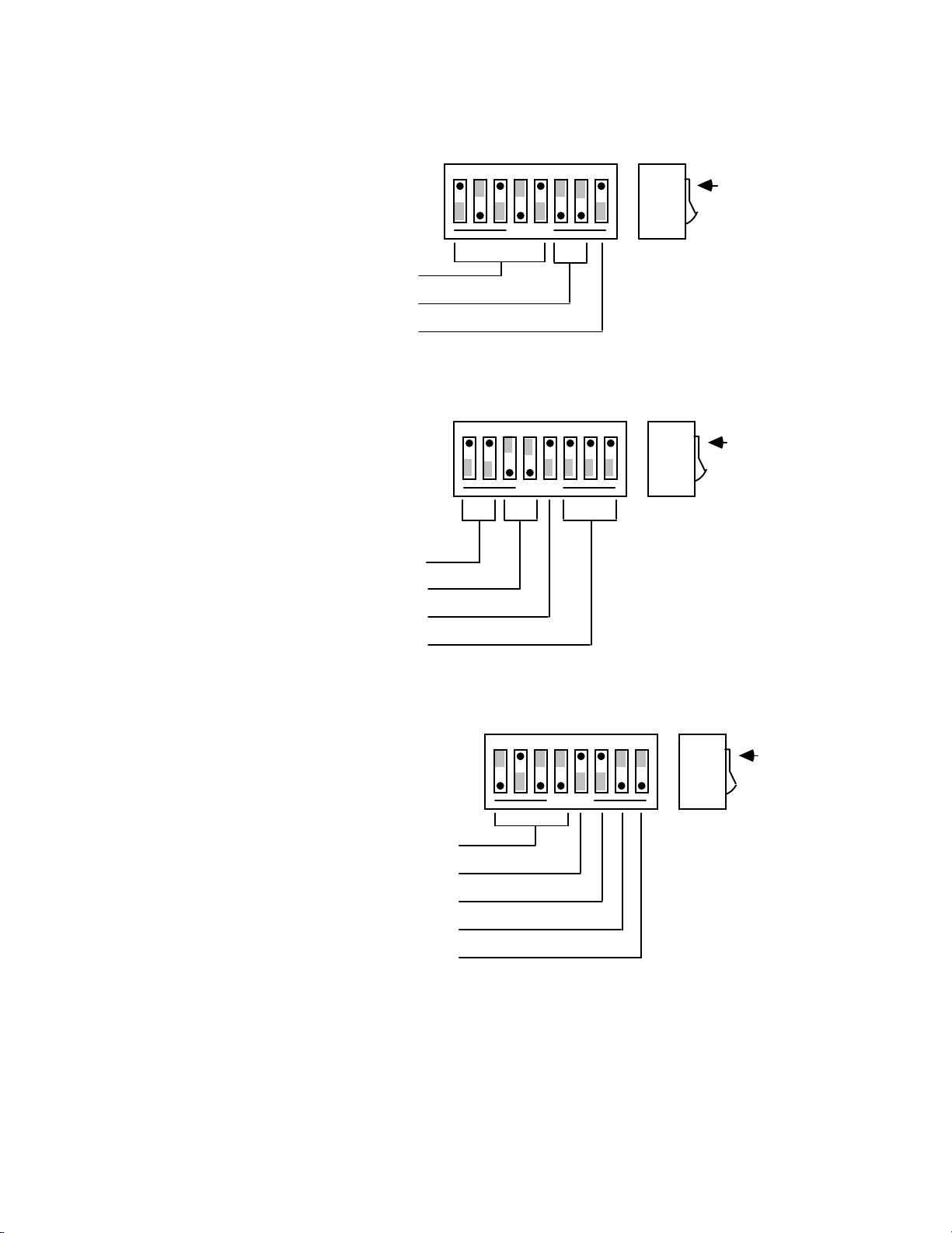
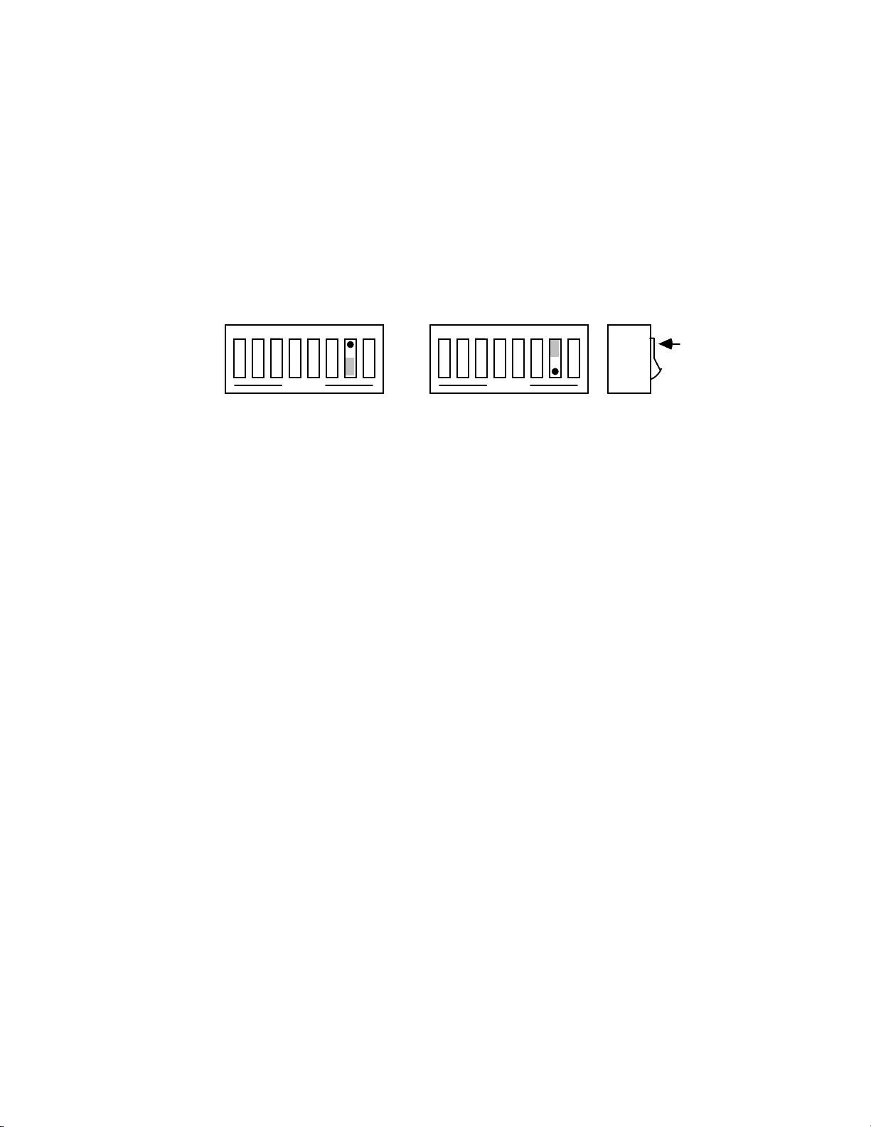
2.2 Configuration
Three DIP switches internal to the Micro488/EX set the configuration of the
interface. NOTE: Selectable functions are read ONLY at power-on and should only be
set prior to applying power to the interface. The following figures illustrate the factory
default conditions which are:
Serial Port: IEEE:
9600 Baud Mode = System Controller
8 Data Bits Address = 10
2 Stop Bits Bus Terminator = CR-LF; EOI Disabled
No Parity Talk-back E nabled
Serial Terminator = CR-LF
Echo Disabled
RTS/CTS Handshake
2.1
Page 16
Section 2 Getting Started
SW3 Factory Default Settings
IEEE Addr
IEEE Term
EOI
SW2 Factory Default Settings
Mode
Serial Term
Echo
Parity
12345678
SW3
OPEN
10
CR-LF
Disabled
12345678
SW2
SC
CR-LF
No Echo
No Parity
OPEN
Switch
Side
View
Switch
Side
View
DOT
DOT
SW1 Factory Default Settings
Baud Rate
Handshake
Word Length
Pass Thru Feature
Stop Bits
12345678
SW1
9600
RTS/CTS
8 Data Bits
Enabled
2 Stop Bits
OPEN
Switch
Side
View
DOT
2.2
Page 17

Section 2 Getting Started
Note that the Micro488/EX comes configured as an IEEE controller. In this mode
the Micro488/EX is designed to allow a serial host computer to control up to 14 IEEE
488 devices. This mode of operation is described in detail, along with its command
descriptions, in Sections 3, 4 and 5. Theses sections also cover the peripheral mode of
operation.
The Micro488/EX can be configured to transparently communicate with a single
IEEE peripheral, such as a plotter. This Controller Pass-Thru mode is described in
detail in Section 6.
The Micro488/EX may also be configured as a transparent IEEE Pass-Thru
Peripheral. As a Pass-Thru Peripheral, the Micro488/EX allows an IEEE controller to
communicate with a serial device. The Peripheral Pass-Thru mode of operation is
described in detail in Section 7.
To modify any of these defaults, follow this simple procedure: Disconnect the
power supply from the AC line and from the interface. Disconnect any IEEE or serial
cables prior to disassembly.
WARNING
Never open the Micro488/EX case while it is
connected to the AC line. Failure to observe this
warning may result in equipment failure, personal
injury or death.
Remove the four screws located in each corner of the rear panel. Hold the case
firmly and pull the rear panel outward, noting the slot location of the main circuit
board. Modify those parameters which are appropriate for your installation and
reassemble the unit. Slide the main circuit board into the previously noted slot and
finish reassembly by tightening the four screws into the rear panel.
2.3 Serial Port Settings
The first parameters to configure are those that correspond to the RS-232/RS-422
port. These include baud rate, word length, number of stop bits, parity selection and
type of serial handshake. Each of these are described in the following sections.
2.3
Page 18
Section 2 Getting Started
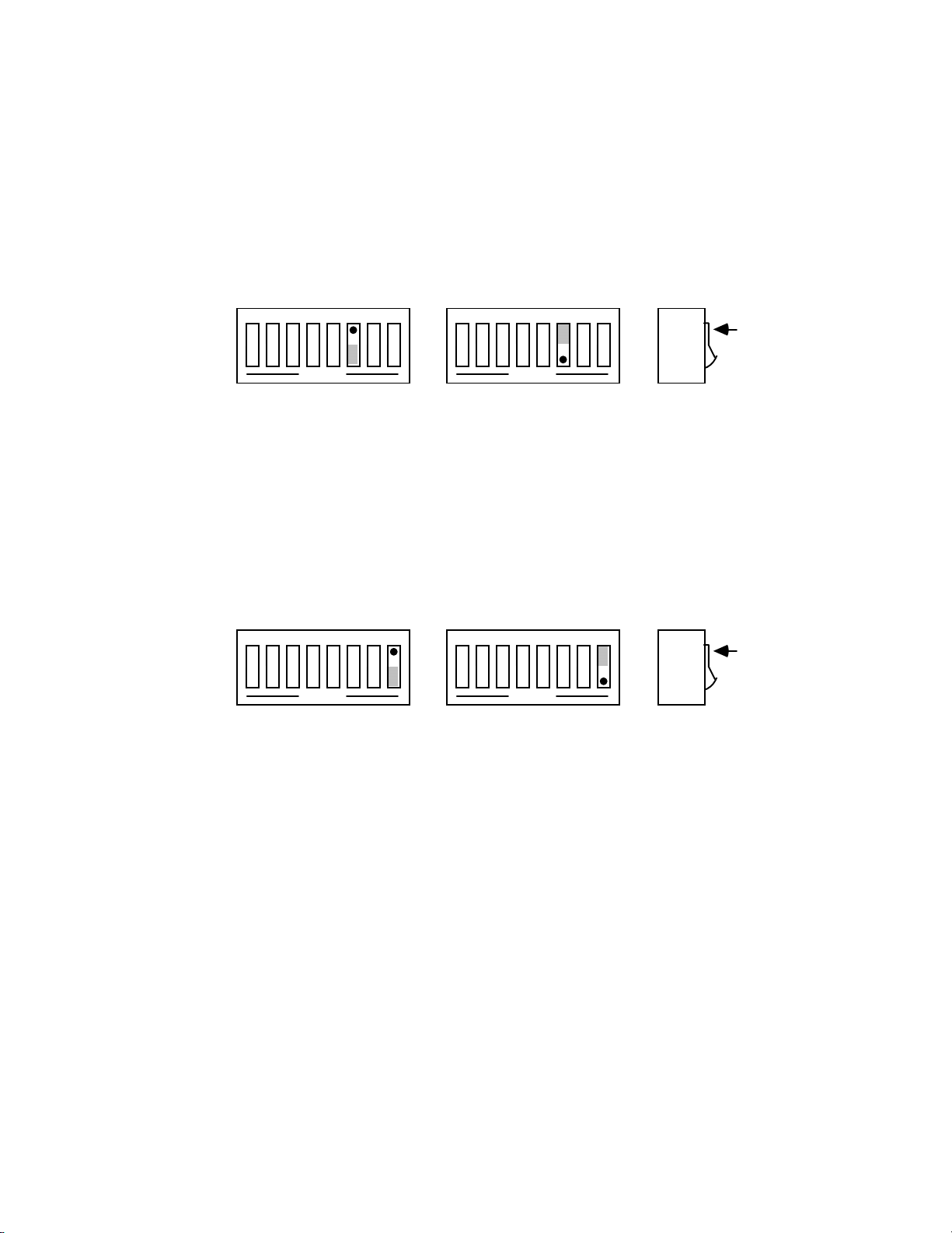
2.3.1 Serial Baud Rate Selection
Baud rate defines the number of serial bits per second transferred into
and out of the serial interface. SW1-1 through SW1-4 determine the serial
baud rate. The factory default baud rate is 9600 baud. Baud rates may be
selected from 110 to 19200 baud. Refer to the following diagram for
specific baud rates.
SW1 View for Serial Baud Rate Selection
12345678
110 1800
OPEN
12345678
110 2400
OPEN
12345678
110 3600
OPEN
12345678
135 4800
OPEN
12345678
150 7200
OPEN
12345678
12345678
OPEN
12345678
OPEN
12345678
OPEN
12345678
OPEN
12345678
OPEN
12345678
Switch
Side
View
DOT
300 9600
OPEN
12345678
600 19200
OPEN
12345678
1200 19200
OPEN
OPEN
12345678
OPEN
12345678
OPEN
2.4
Page 19
Section 2 Getting Started
2.3.2 Serial Word Length Selection - Data Bits
SW1-6 determines the number of data bits, often referred to as word
length, for each serial character transmitted or received. The factory default
is 8 data bits.
SW1 View of Serial Word Length (Data Bits) Selection
12345678
OPEN
12345678
OPEN
Switch
Side
View
DOT
8 Data Bits 7 Data Bits
2.3.3 Serial Stop Bit Selection
Switch SW1-8 determines the number of stop bits contained in each
serial character transmitted and received. The factory default is 2 stop bits.
SW1 View for Serial Stop Bit Selection
12345678
OPEN
12345678
1 Stop Bit 2 Stop Bits
Switch
Side
View
OPEN
DOT
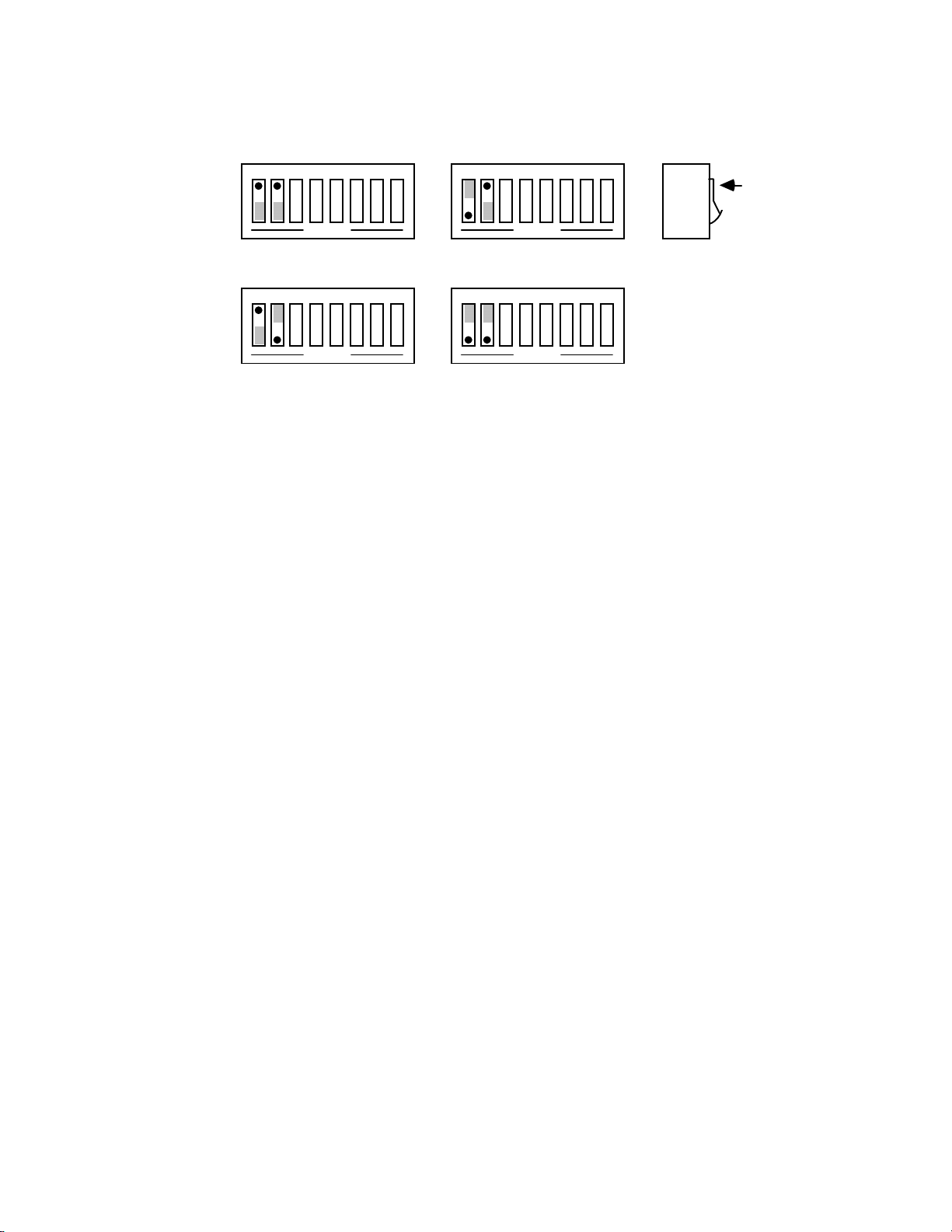
2.3.4 Serial Parity Selection
Serial Parity is selected with S2-6 through S2-8. The Micro488/EX
generates the selected parity during serial transmissions but it does not
check parity on data that is received. The factory default is parity disabled.
2.5
Page 20
Section 2 Getting Started
12345678
12345678
SW2 View for Serial Parity Selection
12345678
OPEN
Odd Parity Mark Parity
12345678
OPEN
Even Parity Space Parity
12345678
OPEN
Parity Disabled
OPEN
OPEN
Switch
DOT
Side
View
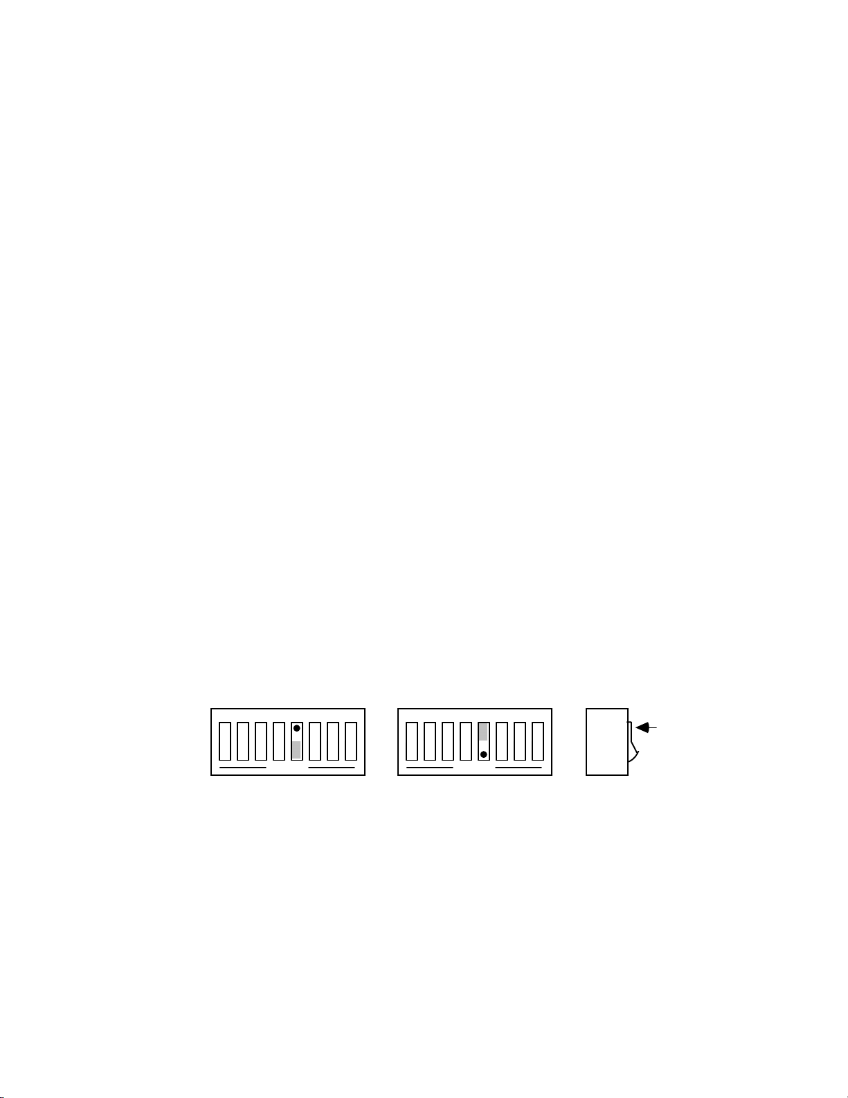
2.3.5 Serial Echo Selection
Serial data sent to the Micro488/EX will be echoed back to the serial
host if SW2-5 is set to the open position. Factory default is Echo Disabled.
12345678
OPEN
Echo Disabled Echo Enabled
SW2 View for Echo Selection
12345678
OPEN
Switch
DOT
Side
View
2.6
Page 21
Section 2 Getting Started
2.3.6 Serial Handshake Selection
Switch SW1-5 is used to select between hardware [
software [
With
value of
&H13
XON/XOFF
XON/XOFF
] when its buffer memory is near full. When issued, there are
] serial handshake control.
, the Micro488/EX issues an
XOFF
RTS/CTS
character [ASCII
] or
greater than 1000 character locations remaining to protect against buffer
overrun. When it is able to accept more information it issues an
character [ASCII value of
issues an
accepts
with.
XON/XOFF
RTS/CTS
enabled. The
character at reset or power-on. The Micro488/EX also
XON
on transmit from the serial host it is communicating
serial control becomes inactive when
output is, however, set to an active high state. The
RTS
&H11
]. With this handshake, the Micro488/EX
XON/XOFF
XON
is
CTS
input is not used for this handshake and may be left floating (unconnected).
With
RTS/CTS
, the Micro488/EX un-asserts
(low) when its
RTS
buffer memory is near full. When un-asserted, there are greater than 1000
character locations remaining to protect against buffer overrun. When it is
able to accept more information it asserts (high)
will not transmit data to the serial host if it detects the
. The Micro488/EX
RTS
input un-
CTS
asserted (low) when configured for this hardware handshake.
The factory default serial control is hardware,
SW1 View for Serial Handshake Selection
12345678
OPEN
RTS/CTS Xon/Xoff
12345678
OPEN
RTS/CTS
Switch
Side
View
.
DOT
2.7
Page 22

Section 2 Getting Started
2.4 Terminator Selection
In the Controller and Peripheral Modes, the Micro488/EX is not sensitive as to
whether CR or LF is used as a serial input terminator to a command. In general, it
requires only one of either to cause command execution. The IEEE input terminator is
fixed to LF. The switches that allow terminator selection, shown in the following
diagrams, set only the serial output and IEEE output terminators for these modes of
operation.
In the transparent Pass-Thru modes, the Micro488/EX can be configured to
provide RS-232 to IEEE 488 and IEEE 488 to RS-232 terminator substitution. This is
useful when interfacing an RS-232 device which only issues carriage return [CR] as an
output terminato r to an IEEE control ler which expects a carriage return followed b y a
line feed [CR-LF].
In the above case, the serial terminator should be selected for CR Only while the
IEEE terminator is set to CR-LF. When a serial CR ch aract er i s recei v ed , it i s d i s carde d
and substituted with an IEEE CR-LF. In the IEEE to RS-232 direction, the IEEE CR is
unconditionally discarded. Upon receipt of the IEEE LF, a serial CR is substituted.
The Micro488/EX can be made totally data transparent in the Pass-Thru modes
by setting both the serial and IEEE terminators to be CR Only or LF Only.
2.4.1 Serial Terminator Selection
SW2-3 and SW2-4 select the serial terminators for the serial input
(Pass-Thru Modes Only) and output. The factory default is CR-LF.
2.8
Page 23

Section 2 Getting Started
SW2 View for Serial Terminator Selection
12345678
OPEN
12345678
OPEN
Switch
Side
View
DOT
CR Only LF-CR
12345678
OPEN
12345678
OPEN
LF Only CR-LF
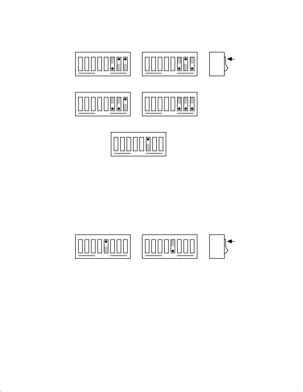
2.4.2 IEEE Bus Terminator Selection
SW3-6 through SW3-8 set the IEEE bus terminators used for data sent
or received (Pass-Thru modes only) by the Micro488/EX. EOI, a line used
to signal the end of a multiple character bus transfer, may also be enabled.
If enabled, EOI is asserted when the last selected bus terminator is sent.
Factory default is CR-LF with EOI disabled.
SW3 View for IEEE Bus Terminator Selection
12345678
OPEN
CR Only LF-CR
12345678
OPEN
LF Only CR-LF
12345678
OPEN
EOI Disabled EOI Enabled
12345678
OPEN
12345678
OPEN
12345678
OPEN
Switch
DOT
Side
View
2.9
Page 24

Section 2 Getting Started
2.5 Mode Selection
SW2-1 and SW2-2 set the major operating mode of the Micro488/EX. There are
four distinct modes of operation.
1. System Controller
2. Peripheral
3. Controller Pass-Thru
4. Peripheral Pass-Thru
As a System Controller, the Micro488/EX accepts simple high-level ASCII
commands from a serial host. It interprets these commands and performs the required
bus action to bi-directionally communicate with up to 14 IEEE devices. As a
Peripheral, the Micro488/EX becomes a bus device. It accepts simple high-level
ASCII commands from a serial host and interprets these commands and status to
communicate with anot her IEEE controller. Applications incl ude computer controlled
automatic test systems. These modes of operation are discussed in Sections 3, 4 and 5.
The IEEE Controller Pass-Thru (RS-232 to IEEE Converter) mode allows a serial
host device to send data to a single IEEE bus peripheral. Applications include
interfacing a listen-only or addressable IEEE printer/plotter to a serial printer port.
Refer to Section 6 for more detailed information on the Controller Pass-Thru mode of
operation.
The Peripheral Pass-Thru mode is used when interfacing a serial device to an
IEEE controller. Data which is sent by the IEEE controller to the Micro488/EX is
transmitted out its serial port. Data received from the serial device is buffered by the
Micro488/EX until read by the IEEE controller. Refer to Section 7 for more detailed
information on the Peripheral Pass-Thru mode of operation.
The factory default is the System Controller mode.
2.10
Page 25
Section 2 Getting Started
SW2 View for Mode Selection
12345678
OPEN
System Controller
12345678
OPEN
Controller Pass-Thru
12345678
OPEN
Peripheral
12345678
OPEN
Peripheral Pass-Thru
Switch
Side
View
DOT
2.6 IEEE Address Selection
SW3-1 through SW3-5 select the IEEE bus address of the Micro488/EX when in
the System Controller, Peripheral and Peripheral Pass-Thru modes. These same
switches are used in the Controller Pass-Thru mode to select the address of the device
that will be controlled. [Refer to Section 6 for additional information]. The address is
selected by simple binary weighting with SW3-1 being the least significant bit and
SW3-5 the most significant. The factory default is address 10.
2.11
Page 26

Section 2 Getting Started
SW3 View for IEEE Address Selection
12345678
0
1
OPEN
0 x 16
1 x 8
0 x 4
1 x 2
0 x 1
+
Switch
Side
View
= 0
= 8
= 0
= 2
= 0
DOT
IEEE Address = 10
2.7 Feature Selections
The functions of the remaining switches are dependent on the mode selected. A
brief description of each of these features follows. You should refer to the listed
sections for additional information.
2.7.1 Controller Pass-Thru Features
In the IEEE Controller (RS-232 to IEEE 488 Converter) mode, SW1-7
is used to determine whether the interface should, after sending the IEEE
bus terminators, address the attached bus device to talk. The factory default
is Talk-back On Terminator enabled.
Refer to Section 6 for complete details on these features.
SW1 View for Controller Talk-Back on Terminator Selection
12345678
OPEN
Talk Back on
Terminator Disabled
12345678
OPEN
Talk Back on
Terminator Enabled
Switch
Side
View
DOT
2.12
Page 27
Section 2 Getting Started
2.7.2 Peripheral Pass-Thru Features
In the Peripheral Pass-Thru (IEEE 488 to RS-232 converter) mode, SW1-7
enables the interface t o assert the SRQ IEEE bus interface lin e to indicate
that it has received the last switch selected serial terminator character from
the serial device. Refer to Section 7 for more information.
SW1 View for Peripheral SRQ on Last Serial Terminator
12345678
OPEN
SRQ on Last
Terminator Disabled
12345678
OPEN
SRQ on Last
Terminator Enabled
Switch
Side
View
DOT
2.8 Serial Interface
The Micro488/EX has the ability to output signal levels that are compatible with
either RS-232 or RS-422. An internal DIP shorting plug determines which electrical
specification is chosen. If the interface is to be connected to an IBM PC/XT/AT/PS2 or
compatible, the RS-232 level should be selected. If it will be connected to a Macintosh
512K/Plus/SE/II, the RS-422 level should be used. For connection to other computers,
refer to the manufacturer's manual to determine which levels are supported.
2.8.1 RS-232/RS-422 Signal Level Selection
The Micro488/EX's factory default signal levels are compatible with
RS-232. To select RS-422 levels, carefully remove the 8 position shorting
plug with a small flat blade screwdriver from J106. Install the DIP jumper
into J205 making certain that all of the pins on the shorting plug are
inserted correctly.
2.13
Page 28
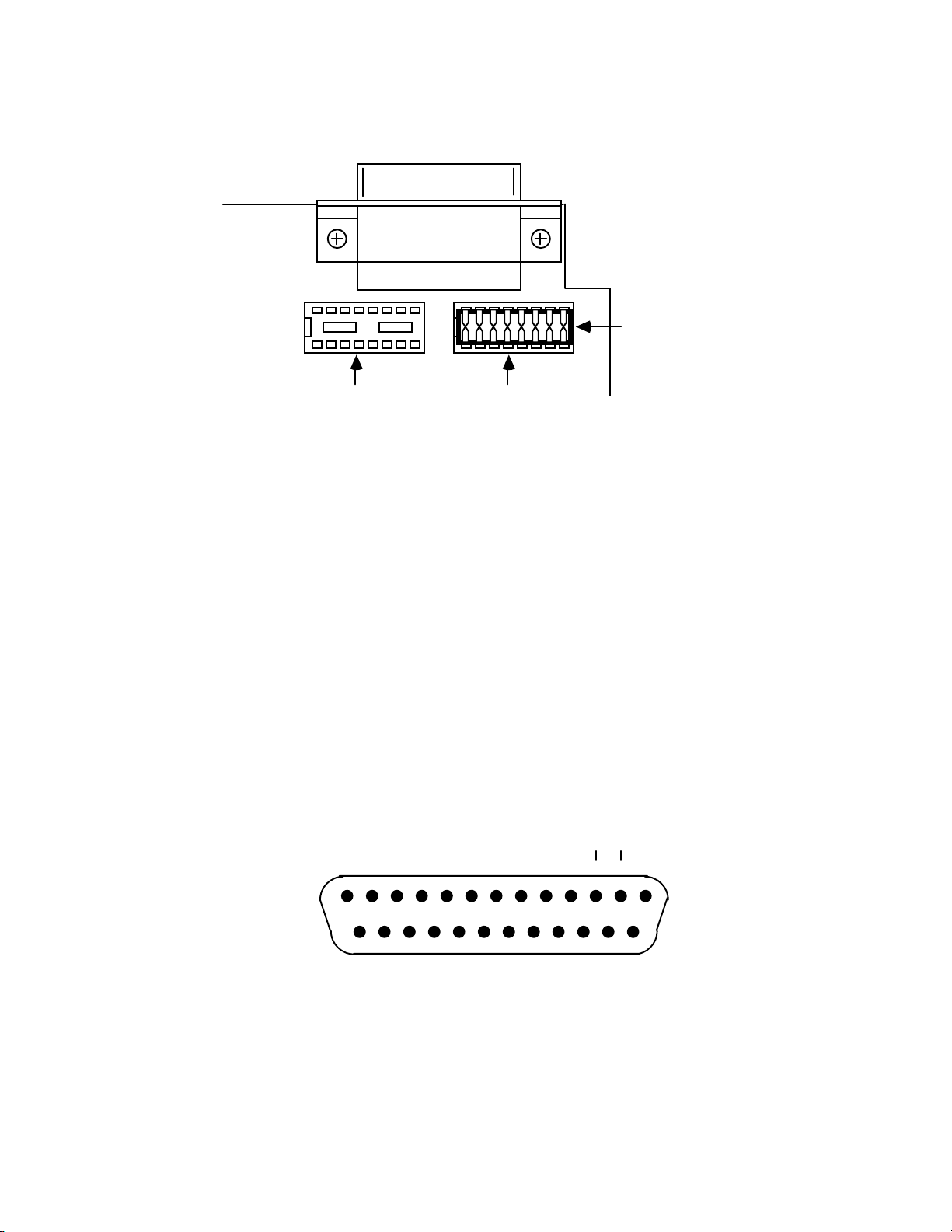
Section 2 Getting Started
Selecting RS-232 or RS-422 Signal Levels
Shorting Plug
J205
RS-422 RS-232
J206
2.8.2 Serial Signal Descriptions
The Micro488/EX is equipped with a standard DB-25S connector on
its rear panel and requires a standard DB-25P mating connector. The
Micro488/EX's connector is configured as DCE type equipment for RS-232
communications, which means the Micro488/EX always transmits data on
Pin 3 and receives data on Pin 2. The following lists and describes the RS232 and RS-422 signals provided on the Micro488/EX.
Rear View of the Micro488/EX's Serial Connector
CTS
+VTEST
GND
13
25
RTS
+VTEST
-RXD
-TXD
1
14
2.14
+TXD
+RXD
Page 29

Section 2 Getting Started
-RxD
-TxD
CTS
Receive Data - Input - Pin 2
This pin accepts serial data sent by the RS-232 or RS-422 host. The
serial data is expected with the word length, baud rate, stop bits and
parity selected by the internal switches. The signal level is low true.
Transmit Data - Output - Pin 3
This pin transmits serial data to the RS-232 or RS-422 host. The
serial data is sent with the word length, baud rate, stop bits and parity
selected by the internal switches. The signal level is low true.
Clear To Send - Input - Pin 4
The
input is used as a hardware handshake line to prevent the
CTS
Micro488/EX from transmitting serial data when the RS-232 host is
not ready to accept it. When
RTS/CTS
internal switches, the Micro488/EX will not transmit data out
handshake is selected on the
-TxD
while this line is un-asserted (low). If the RS-232 host is not capable
of driving this line it can be connected to the
the Micro488/EX. If
XON/XOFF
handshake is selected, the
Vtest
output (Pin 6) of
line
CTS
is not tested to determine if it can transmit data.
RTS
Vtest
Gnd
Request To Send - Output - Pin 5
The
output is used as a hardware handshake line to prevent the
RTS
RS-232/RS-422 host from transmitting serial data if the Micro488/EX
is not ready to accept it. When
RTS/CTS
the internal switches, the Micro488/EX will drive the
handshake is selected on
output
RTS
high when there are greater than 1000 character locations available in
its internal buffer. If the number of available locations drops to less
than 1000, the Micro488/EX will un-assert (low) this output. If
XON/XOFF
handshake is selected, the
line will be permanently
RTS
driven active high.
Test Voltage - Output - Pin 6
This pin is connected to +5 volts through a 1KΩ resistor. It is also
common to
Vtest
on pin 9.
Ground - Pin 7
This pin sets the ground reference point for the other RS-232 inputs
and outputs.
2.15
Page 30
Section 2 Getting Started
Vtest
+RxD
+TxD
Test Voltage - Output - Pin 9
This pin is connected to 5 volts through a 1KΩ resistor. It is also
common to
Vtest
on pin 6.
Receive Data Plus - Input - Pin 14
This pin accepts serial data sent by the RS-422 host. The serial data
is expected with the word length, baud rate, stop bits and parity
selected by the internal switches. The signal level is high true and
only connected to this pin when RS-422 operation is selected. It is
180° out of phase with
-RxD
.
Transmit Data Plus - Output - Pin 16
This pin transmits serial data to the RS-422 host. The serial data is
sent with the word length, baud rate, stop bits and parity selected by
the internal switches. The signal level is high true and only connected
to this pin when RS-422 operation is selected. It is 180° out of phase
with
-TxD
.
2.8.3 Serial Cable Wiring Diagrams
If a cable was not purchased with the interface, the following diagrams
will be helpful in making your own cable. Simple soldering skills and an
attention to detail will ensure successful construction.
Macintosh to Micro488/EX Wiring Diagram (RS-422)
Macintosh to Micro488/EX
DB-9 Male DB-25 Male
RTS
CTS
-TxD
Gnd
-RxD
+TxD
+RxD
6
7
5
3
9
4 14 +Rxd
8 16 +Txd
4
5
2
7
3
CTS
RTS
-RxD
Gnd
-Txd
2.16
Page 31

Section 2 Getting Started
Macintosh II/SE/Plus to Micro488/EX Wiring Diagram
(RS-422)
Macintosh II/SE/Plus to Micro488/EX
Mini DIN8 Male DB-25 Male
RTS
CTS
-TxD
Gnd
-RxD
+TxD
+RxD
1
2
3
4
5
4
CTS
5
RTS
2
-RxD
7
Gnd
3
-Txd
6 14 +Rxd
8 16 +Txd
IBM PC/XT/PS2 to Micro488/EX Wiring Diagram
(RS-232)
IBM PC/XT/PS2 to Micro488/EX
DB-25 Female DB-25 Male
-TxD
2
2
-RxD
-RxD
RTS
CTS
DSR
Gnd
3
4
5
6
3
4
5
6
-TxD
CTS
RTS
Vtest
7 7 Gnd
2.17
Page 32

Section 2 Getting Started
IBM AT to Micro488/EX Wiring Diagram (RS-232)
IBM AT to Micro488/EX
DB-9 Female DB-25 Male
DCD
-RxD
-TxD
DTR
Gnd
DSR
RTS
CTS
Note: Standard AT 9 Pin to 25 Pin adapter cables are not wired as shown above and will not
work with the Micro488/EX. Order IOtech PN CA-23.
1
2
3
4
5
6
7
8
3
-TxD
2
-RxD
7
Gnd
4 CTS
5 RTS
2.9 General Operation
Refer to the following sections for specific operational modes. This sub-section
gives a general test of functionality. After setting the power on defaults and
reassembling the Micro488/EX, plug the power supply connector into the rear jack on
the interface.
CAUTION
Never install the power supply into the interface
while it is connected to AC line power. Failure to
observe this caution may result in damage to the
Micro488/EX.
WARNING
The power supply provided with the interface is
intended for INDOOR USE ONLY. Failure to
observe this warning could result in equipment
failure, personal injury or death.
2.18
Page 33

Section 2 Getting Started
After installing the power supply connector into the interface, plug the power
supply into AC line power. Place the rear panel power switch in the ON [1] position.
All the front panel indicators should light momentarily while the Micro488/EX
performs an internal ROM and RAM self check. At the end of this self check all
indicators except POWER should turn off.
If there is an error in the ROM checksum, all of the LEDs will remain on.
Flashing LEDs indicates a RAM failure. Should such an error occur, turn the rear
panel switch to the OFF [0] position and retry the above procedure.
If the front panel indicators do not flash and the POWER indicator does not
remain lit there may not be any power supplied to the interface. In this event, check the
AC line and the rear panel connection of the power supply for proper installation. If the
problem is unresolved, refer to the Service Information section of this manual.
If proper operation is obtained, connect an interface cable to the rear of the
Micro488/EX [ 25-Pin Sub-D ]. Connect the other end to the host's serial port. Except
for connecting IEEE bus instruments, the Micro488/EX is installed and ready to use.
WARNING
The Micro488/EX makes its earth ground
connection through the serial interface cable. It
should only be connected to IEEE bus devices after
being first connected to the host. Failure to do so
may allow the Micro488/EX to float to a bus
device test voltage. This could result in damage to
the interface, personal injury or death.
2.19
Page 34

Section 2 Getting Started
2.10 Is Anyone Out There?
Before connecting any IEEE bus devices to the Micro488/EX, try this simple
operational check. The Micro488/EX must be configured for either System Controller
of Peripheral mode operation. This test will not work in either of the Pass-Thru modes.
Running BASIC on the host, or any programming language which supports the
serial ports, type the following (or its equivalent).
OPEN "COM1:9600,N,8,2,cd,ds" AS 1 [Return]
PRINT #1,"HELLO" [Return]
LINE INPUT #1,A$ [Return]
PRINT A$ [Return]
The Micro488/EX will respond with (and the host will display):
Micro488/EX Revision N.N Copyright (C) 1988 IOtech Inc.
where
is the release and revision number of the firmware.
N.N
If you obtain the above response then your Micro488/EX is alive and well and
ready to connect your host to the powerful IEEE-488 General Purpose Interface Bus. If
you did not receive the above message, check for proper connection and fit of the
interface cable. If, after reviewing the interface for proper installation, you do not
obtain the desired results then refer to the Service Information section of this manual.
2.20
Page 35

Section 3 IEEE Operating Modes
IEEE Operating Modes
3.1 Introduction
There are four types of IEEE b us devices: Activ e Controllers, Peri pherals, Talkonly devices, and Listen-always devices. Talk-only and Listen-always devices are
usually used together, in simple systems, such as a Talk-only digitizer sending results
to a Listen-always plotter. In these simple systems no controller is needed because the
talker assumes that it is the only talker on the bus, and the listener(s) assume that they
are all supposed to receive all the data send over the bus. This is a simple and effective
method of transferring data from one device and another, but is not adequate for more
complex systems where, for example, one computer is controlling many different bus
devices.
In more complex systems, the Active Controller sends commands to the various
bus Peripherals telling them what to do. Commands such as Unlisten, Listen Address
Group, Untalk, and Talk Address Group are sent by the controller to specify which
device is to send data, and which are to receive it. For more details about the IEEE bus
protocols see the section 'IEEE 488 Primer'.
When an IEEE bus system is first turned on, some device must be the Active
Controller. This device is the System Controller and always keeps some control of the
bus. In particular, the System Controller controls the Interface Clear (IFC) and Remote
Enable (REN) bus management lines. By asserting Interface Clear, the System
Controller forces all the other bus devices to stop their bus operations, and regains
control as the Active Controller.
3.2 Operating Mode Transitions
The System Controller is initially the Active Controller. It can, if desired, Pass
Control to another device and thereby make that device the Active Controller. Note
that the System Controller remains the System Controller, even when it is not the
Active Controller. Of course, the device to which control is passed must be capable of
taking on the role of Active Controller. It would make no sense to try to pass control to
a printer. Control should only be passed to other computers that are capable, and
ready, to become the Active Controller. Further, note that there must be exactly one
System Controller o n the IEEE bus. Al l other po tential con trollers mus t be config ured
as Peripherals when they power up.
3.1
Page 36

Section 3 IEEE Operating Modes
The state diagram below shows the relationships between the various operating
modes. The top half of the state diagram shows the two operating states of a System
Controller. At power on, it is the active controller. It directs the bus transfers by
sending the bus commands mentioned previously. It also has control of the Interface
Clear and Remote Enable bus lines. The System Controller can pulse Interface Clear to
reset all of the other bus devices.
As shown in the diagram, the System Controller can pass control to some other
bus device and thereby become a Peripheral to the new Active Controller. If the
System Controller receives control from the new Active Controller, then it will once
again become the Active Controller. The System Controller can also force the Active
Controller to relinquish control by asserting the Interface Clear signal.
System Controller (SC)
Active
System
Controller
SC•CA
Power On
Controller Active (CA) Peripheral (*CA)
Active
Controller,
Not System
Controller
*SC•CA
Passes Control
Controller,
Not Active
Receives Control or
Asserts Interface Clear
Passes Control or
Detects Interface Clear
Not System
Receives Control
Not System Controller (*SC)
System
SC•*CA
Power On
Peripheral,
Controller
*SC•*CA
IEEE Bus Operating Modes State Diagram
3.2
Page 37

Section 3 IEEE Operating Modes
The bottom half of the state diagram shows the two operating states of a Not
System Controller device. At power on, it is a Peripheral to the System Controller
which is the Active Controller. If it receives control from the Active Controller, it
becomes the new Active Controller. Even though it is the Active Controller, it is still
not the System Controller. The System Controller can force the Active Controller to
give up control by asserting Interface Clear. The Active Controller can also give up
control by Passing Control to another device, which may or may not be the System
Controller.
In summary, a bus device is set in hardware as either the sole System Controller
in the system, or as a non-System Controller. At power on, the System Controller is
the Active Controller, and the other devices are Peripherals. The System Controller
can give up control by Passing Control, and can regain control by asserting Interface
Clear, or by receiving control. A Peripheral can become the Active Controller by
receiving control, and can give up control by Passing Control, or upon detecting
Interface Clear.
3.3 System Controller Mode
The most common the Micro488/EX configuration is as the System Controller,
controlling several IEEE bus instruments. In this mode, the Micro488/EX can perform
all of the various IEEE bus protocols necessary control and communicate with any
IEEE 488 bus devices. As the System Controller in the Active Controller mode, the
Micro488/EX can use all of the commands available for the Active Controller state,
plus control the Interface Clear and Remote Enable lines. The allowed bus commands
and their actions are as follows:
ABORT
LOCAL
Pulse Interface Clear.
Unassert Remote Enable, or send Go To Local to selected
devices.
REMOTE
Assert Remote Enable, optionally setting devices to
Remote.
LOCAL LOCKOUT
Prevent local (front-panel) control of bus devices.
CLEAR
TRIGGER
Clear all or selected devices.
Trigger selected devices.
3.3
Page 38

Section 3 IEEE Operating Modes
ENTER
OUTPUT
PASS CONTROL
Receive data from a bus device.
Send data to bus devices.
Give up control to another device which becomes the Active
Controller.
SPOLL
PPOLL
PPOLL CONFIG
PPOLL DISABLE
PPOLL UNCONFIG
Serial Poll a bus device, or check the Service Request state.
Parallel Poll the bus.
Configure Parallel Poll responses.
Disable the Parallel Poll response of selected bus devices.
Disable the Parallel Poll response of all bus devices.
SEND Send low-level bus sequences.
RESUME
Unassert Attention. Used to allow Peripheral-to- Peripheral
transfers.
3.4 System Controller, Not Active Controller Mode
After Passing Control to another device, the System Controller is no longer the
Active Controller. It acts as a Peripheral to the new Active Controller, and the allowed
bus commands and their actions are modified accordingly. However, it still maintains
control of the Interface Clear and Remote Enable lines. The available bus commands
and their actions are:
ABORT
Pulse Interface Clear.
LOCAL Unassert Remote Enable.
REMOTE
ENTER
Assert Remote Enable.
Receive data from a bus device as directed by the Active
Controller.
OUTPUT
Send data to bus devices as directed by the Active
Controller.
REQUEST Set own Serial Poll request (including Service Request)
status.
SPOLL
Get own Serial Poll request status.
3.4
Page 39

Section 3 IEEE Operating Modes
As a bus Peripheral, the Micro488/EX must respond to the commands issued by
the Active Controller. The controller can, for example, address the Micro488/EX to
listen in preparation for sending data. There are two ways of detecting our being
addressed to listen: through the
or ON <
ARM
event> DOMACRO
STATUS
commands.
command, or by detecting an event with the
The
STATUS 1
command can be used to watch for commands from the Active
Controller. The Operating Mode, which is a "P" while the Micro488/EX is a
Peripheral, will change to a "C" if the Active Controller Passes Control to the
Micro488/EX. The Addressed State will go from Idle ("I") to Listener ("L") or Talker
("T") if the Micro488/EX is addressed to listen or to talk, and will go back to Idle ("I")
when the Active Controller issues Unlisten (UNL), Untalk (UNT), or specifies another
talker (TAG). The Triggered ("T1") and Cleared ("C1") indicators will be set when the
Micro488/EX is triggered or cleared, and reset when
STATUS 1
is read. The Address
Change indicator will be set ("G1") when the address state changes. These indicators
allow the program to sense the commands issued to the Micro488/EX by the Active
Controller. The following BASIC program fragment illustrates the use of the Address
Change and Addressed State indicators to communicate with the Active Controller:
First we check
STATUS
until it indicates that there has been an address change:
200 PRINT#1,"STATUS1"
210 INPUT#2 ST$
220 'Has there been no Address Change?
230 IF MID$(ST$,7,1)="0" THEN 200
240 'Are will still in the idle state?
250 STATE$=MID$(ST$,9,1)
260 IF STATE$="I" THEN 200
270 'Are we addressed to listen?
280 IF STATE$="L" THEN 400
290 'Are we addressed to talk?
300 IF STATE$="T" THEN 500
310 PRINT "BAD ADDRESSED STATE VALUE: ";ST$: STOP
3.5
Page 40

Section 3 IEEE Operating Modes
If we are addressed to listen then we
ENTER
a line from the controller and print it
out.
400 'Listen state
410 PRINT#1,"ENTER"
420 LINE INPUT#1,A$
430 PRINT A$
440 GOTO 200
If we are addressed to talk then we
INPUT
a line from the keyboard and
it to the controller.
500 'Talk state
510 LINE INPUT A$
520 PRINT#1,"OUTPUT;";A$
530 GOTO 200
It is also possible to detect these conditions with the
DOMACRO
commands and handle them in an exception as described in Section 5. The
various arm conditions and their meanings are as follows:
or ON <
ARM
OUTPUT
event
>
SRQ
PERIPHERAL
CONTROLLER
TRIGGER
CLEAR
TALK
LISTEN
IDLE
The internal Service Request state is set. See the
SPOLL
command in Section 5.
the Micro488/EX is in the Peripheral (*CA) operating
mode.
the Micro488/EX is the Active Controller (CA).
the Micro488/EX, as a Peripheral, has received a Trigger
bus command.
the Micro488/EX, as a Peripheral, has received a Clear bus
command.
the Micro488/EX is in the Talk state and can
OUTPUT
to the
bus.
the Micro488/EX is in the Listen state and can
ENTER
from
the bus.
the Micro488/EX is in neither the Talk nor Listen state.
3.6
Page 41

Section 3 IEEE Operating Modes
CHANGE An Address Change has occurred, i.e. a change between
Peripheral and Controller, or among Talk, Listen, and Idle
has occurred.
ERROR
An error, either command or bus, has been detected by the
Micro488/EX.
STARTUP
The non-volatile Macro capability provides the stand-alone
controller feature by allowing the Micro488/EX to execute a
Macro at
STARTUP
.
3.5 Not System Controller Mode
If the Micro488/EX is configured as not the System Controller then, at power on,
it will be a bus Peripheral. It might use a program like the one described previously to
communicate with the Active Controller. The bus commands available to the
Micro488/EX when it is not the System Controller and not the Active Controller
(*SC•*CA) are:
ENTER
Receive data from a bus device as directed by the Active
Controller.
OUTPUT
Send data to bus devices as directed by the Active
Controller.
REQUEST Set own Serial Poll request (including Service Request)
status.
SPOLL
Get own Serial Poll request status.
3.6 Active Controller, Not System Controller Mode
If the Active Controller Passes Control to the Micro488/EX then it will become
the new Active Controller. This can be detected by the
ed event. As an Active Controller, but not the System Controller, the following
ARM
STATUS
command or as an
bus commands are available:
*ABORT
Assert Attention and send My Talk Address to stop any bus
transfers.
3.7
Page 42

Section 3 IEEE Operating Modes
LOCAL
LOCAL LOCKOUT
CLEAR
TRIGGER
ENTER
OUTPUT
PASS CONTROL
SPOLL
PPOLL
PPOLL CONFIG
PPOLL DISABLE
PPOLL UNCONFIG
SEND
RESUME
Send Go To Local to selected devices.
Prevent local (front-panel) control of bus devices.
Clear all or selected devices.
Trigger selected devices.
Receive data from a bus device.
Send data to bus devices.
Give up control to another device which becomes the Active
Controller.
Serial Poll a bus device, or check the Service Request state.
Parallel Poll the bus.
Configure Parallel Poll responses.
Disable the Parallel Poll response of selected bus devices.
Disable the Parallel Poll response of all bus devices.
Send low-level bus sequences.
Unassert Attention. Used to allow Peripheral-to- Peripheral
transfers.
3.7 Controller Pass-Thru Mode
This mode is intended to provide bi-directional data transparent conversion
between an RS-232/RS-422 host computer and an IEEE 488 peripheral, such as a
printer or a HPIB™ plotter. The operation of this mode is covered in Section 6 of this
manual.
3.8 Peripheral Pass-Thru Mode
This mode is intended to provide bi-directional data transparent conversion
between an IEEE 488 controller and a serial device. This Peripheral Pass-Thru mode
does not require the serial device to control data to it. The is no command line parser
and, therefore, requires no serial commands. This mode of operation is described in
Section 7 of this manual.
3.8
Page 43

Section 4 General Programming
General Programming
4.1 Introduction
This section provides example information for programming the Micro488/EX in
the Controller and Peripheral modes using the MACRO and clock features. The
concentration is placed on Micro488/EX commands and not specifically on the
programming language. All the examples shown use one of the TERMINAL programs
listed in Appendix D. Other languages may be used as long as they provide similar
functionality. Using this type of terminal program is recommended to become familiar
with the Micro488/EX and any new bus device as it allows direct human-device
interaction.
4.2 Memory Usage
To better understand MACRO programming on the Micro488/EX, a description of
how the system allocates memory for different functions will allow the user to tailor
programming for the most effective use.
Memory in the Micro488/EX is dynamically allocated for the serial input, serial
output, MACRO and LOG buffers. This allows for the most efficient partitioning of
memory for any given application. This memory is kept in the USER 'heap' (a
vernacular for 'heap of memory') until required by the system. A MEMORY command
has been included in the Micro488/EX to report the available memory in the USER
heap.
4.2.1 Serial I/O Buffers
At power on, each serial buffer is allocated an empty 127 byte minibuffer or queue. When the serial input [or output] requires more buffer
space, additional queues are allocated. When a queue is empty, it is released
from the buffer so that it may be re-allocated when, and where, required.
There are approximately 240 available queues for a total of 29,000
bytes of buffer (character) space. Queues are continually allocated and
released as required. Of the 240 available queues, 230 are assigned to the
4.1
Page 44

Section 4 General Programming
USER heap and issued without regard to controlling the receipt and
buffering of additional data.
When the serial input buffer requests one of the last 10 queues (1270
character locations left), it signals the serial host that it should stop sending
data. This is accomplished by either un-asserting the serial hardware
handshake
line or issuing an
RTS
XOFF
character (
&h13
), depending on
which serial handshake control has been switch selected. When more than
10 queues become available, it asserts
(
&h11
).
or issues an
RTS
XON
character
4.2.2 Log Buffer
The
buffer is similar to the serial output buffer. It can, under
LOG
program control, accept the data which would normally go to the serial
output buffer. It differs from the serial output buffer in that the data in the
buffer is maintained when the power is off. The
LOG
buffer is initially
LOG
allocated a 127 byte queue and, if required, acquires additional memory
from the USER heap. It retains these queues until
ERASE
d by the user
under program control.
4.2.3 Macro Buffers
MACRO
ERASE
MACRO
queues are not allocated until a macro is defined. If a
d, all the memory allocated to it is returned to the USER heap. The
text is stored into this queue exactly the way it was received from
the serial input. Syntax error checking is not performed when the
created. If the length of the
MACRO
is longer than the 127 bytes allocated,
MACRO
MACRO
is
is
additional memory is allocated as required in 127 byte lengths. A single
MACRO
could be defined to consume the entire available USER heap.
When a
MACRO
is executed, a copy of the
MACRO
buffer is made and
placed at the start of the serial input buffer. If there is no available memory
in the USER heap, an
OUT OF MEMORY
error is generated which will cause
the front panel error LED to flash.
4.2
Page 45

Section 4 General Programming
4.2.4 Changing Operational Modes
If memory is allocated from the USER heap for
LOG
and
MACRO
buffers in the Controller or Peripheral modes, and the operational mode is
changed to one of the Pass-Thru modes, this memory remains allocated and
is not available to the Pass-Thru mode. Pass-Thru modes will function as
described but will not have the full memory available to them. Upon
returning to the Controller or Peripheral mode, the
LOG
and
MACRO
buffers
will be un-modified.
4.3 Clock and Timer Functions
The Micro488/EX has a built in time of day, day of week and date clock. Most
timer features, with the exception of
this hardware.
TIME OUT
and
DELAY
TIME OUT
are functions of the Micro488/EX's firmware
and
DELAY
, are directly a function of
operating system. As a result, some time skew may be observed between these
commands with respect to the clock.
Both 12 and 24 hour time output formats are available from the clock. The
relationship between the 12 and 24 hour operations are…
24 Hour 12 Hour
Midnight 00:00:00 12:00:00 AM
01:00:00 01:00:00 AM
……
11:59:59 11:59:59 AM
Noon (Midday) 12:00:00 12:00:00 PM
13:00:00 01:00:00 PM
……
23:59:59 11:59:59 PM
4.3.1 Time
While running one of the TERMINAL programs in Appendix D, type
the following on the PC's keyboard…
HELLO
<return>
4.3
Page 46

Section 4 General Programming
The Micro488/EX will respond with…
Micro488/EX Revision 1.0 Copyright (C) 1988 IOtech
Inc.
Now type…
SET TIME 1:00 PM
TIME
<return>
<return>
The Micro488/EX will respond with…
01:00:02 PM
The actual time returned will depend, of course, on how long an interval
passes between typing the
SET TIME
and
TIME
commands.
Now type the following to change the
TIME FORMAT HH:MM:SS
TIME
TIME
output to a 24 hour format.
<return>
<return>
The Micro488/EX will respond with…
13:00:15
To test the functionality of the WAIT command, type…
SET TIME 1:00 PM
WAIT TIME 1:01 PM
TIME
<return>
<return>
<return>
There will be a one minute delay at which time the Micro488/EX will
respond with…
13:01:00
For more information, refer to the following TIME related commands.
SET TIME
TIME
TIME FORMAT
WAIT
4.4
Page 47

Section 4 General Programming
4.3.2 Date
While running one of the TERMINAL programs in Appendix D, type
the following on the PC's keyboard…
SET DATE JULY 4, 1988
DATE
<return>
<return>
The Micro488/EX will respond with…
July 4, 1988
To test the functionality of the CASE command, type…
CASE UPPER
DATE
<return>
<return>
The Micro488/EX will respond with…
JULY 4, 1988
Now type the following to change the
DATE FORMAT MM-DD-YY
DATE
DATE
output to a numeric format.
<return>
<return>
The Micro488/EX will respond with…
07-04-88
For more information, refer to the following DATE related commands.
SET DATE
DATE
DATE FORMAT
WAIT
4.5
Page 48

Section 4 General Programming
4.3.3 Day of Week
While running one of the TERMINAL programs in Appendix D, type
the following on the PC's keyboard…
SET DAY MONDAY
DAY
<return>
<return>
The Micro488/EX will respond with…
MONDAY
Now type the following to change the
DAY FORMAT D
DAY
output to a numeric format.
DAY
<return>
<return>
The Micro488/EX will respond with…
2
For more information, refer to the following DAY related commands.
SET DAY
DAY
DAY FORMAT
WAIT
4.3.4 Combinations
The DATE, DAY and TIME commands may be sent within a single
command line in any order, as long as each command appears only once.
Type the following on the PC's keyboard…
DAY FORMAT DAY
DATE FORMAT MONTH DD, YYYY
TIME FORMAT HH:MM:SS AM
DAY DATE TIME
<return>
<return>
<return>
<return>
The Micro488/EX will respond with…
MONDAY JULY 4, 1988 1:05:00 PM
4.6
Page 49

Section 4 General Programming
4.4 MACRO Programming
The
MACRO
commands and execute them with a single
capable of storing up to 100 different
Defining a
command allows the user to build a file of sequential Micro488/EX
command. The Micro488/EX is
MACRO
command. Each subsequent
MACRO
DOMACRO
MACRO
s.
is initiated by issuing the
character following this command, including terminators and intervening spaces, is
saved in a buffer up to, and including, the
appends the
MACRO
number to the
MACRO
macro can then be executed by issuing a
are included within the
If a
MACRO
USER heap. If a
has not been defined, it does not consume any memory from the
MACRO
MACRO
has been defined, any
are not checked until the
ENDM
buffer as a two digit decimal number. The
DOMACRO
returned to the USER heap prior to requesting memory to re-define the
initial size of an allocated
MACRO
than 127 bytes are required to store the
buffer is 127 character locations (bytes). If more
MACRO
byte increments. If there is no available memory in the USER heap, an '
MEMORY
' error occurs and any memory allocated to that
. After the
ENDM
, the Micro488/EX
command. Any syntax errors that
is executed.
MACRO
. The
MACRO
MACRO
buffer previously allocated is
, additional memory is allocated in 127
OUT OF
MACRO
is returned to the heap.
4.4.1 Creating a MACRO
The user defines a macro by the following command sequence:
MACRO 1
list of valid Micro488/EX commands
<
>
ENDM
Type the following on the PC's keyboard to create a simple macro…
MACRO 1
DAY
DATE
ENDM
<return>
<return>
<return>
<return>
4.7
Page 50

Section 4 General Programming
Any of the
the host with the
MACRO
READ
command buffers can be reported, or sent, back to
command. This command will output the data in the
respective buffer but will not delete the information contained in the buffer.
To have the Micro488/EX report the contents of this macro buffer type…
READ 1
<return>
The Micro488/EX will respond with…
DAY
DATE
ENDM01
4.4.2 Executing a MACRO
Macros are executed by the DOMACRO command. This command
specifies the macro number to execute. Type the following…
DOMACRO 1
<return>
The Micro488/EX will respond with…
MONDAY
JULY 4, 1988
Optionally, the
execute the
MACRO
DOMACRO
(loop). The number of times a single
command can specify the number of times to
execute is 255. Type the following…
DOMACRO 1,3
The Micro488/EX will respond with…
MONDAY
JULY 4, 1988
MONDAY
JULY 4, 1988
MONDAY
JULY 4, 1988
<return>
MACRO
can
4.8
Page 51

Section 4 General Programming
If it is desired to execute a MACRO more than the allowed 255 times,
another MACRO can be created to invoke the first. For example…
MACRO 2
DOMACRO 1,200
DOMACRO 1,200
DOMACRO 1,200
ENDM
<return>
<return>
<return>
<return>
<return>
DOMACRO 2 <return>
will execute MACRO 1 a total of 600 (200+200+200) times while…
DOMACRO 2,100 <return>
will execute MACRO 1 a total of 60000 (100*[200+200+200]) times.
An additional time interval specifier, in seconds, can be included with
the number of times specifier, to set a precise delay from the start of one
execution to the start of the next. Only one interval timer is provided.
Having two
IN USE
error. Type the following…
MACRO
s trying to use it at the same time will cause a
TIMER
MACRO 1 <return>
TIME
ENDM
<return>
<return>
MACRO 2 <return>
SET TIME 12:00 PM
DOMACRO 1,3,5
TIME
ENDM
DOMACRO 2
<return>
<return>
<return>
<return>
<return>
4.9
Page 52

Section 4 General Programming
The Micro488/EX will respond with…
12:00:00
< 5 Second Delay>
12:00:05
< 5 Second Delay>
12:00:10
12:00:10
MACRO
executing
MACRO
, a '
s can execute other
MACRO
. If a
MACRO
MACRO RECURSION
MACRO
tries to invoke itself or an already executing
' error will be generated.
s but can not execute already
A method has been provide to determine the loop number of the
MACRO
MACRO 1
COUNT
TIME
ENDM
DOMACRO 2
being executed. Type…
<return>
<return>
<return>
<return>
<return>
The Micro488/EX will respond with…
3
12:00:00
< 5 Second Delay>
2
12:00:05
< 5 Second Delay>
1
12:00:10
12:00:10
4.10
Page 53

Section 4 General Programming
4.4.3 Debugging a MACRO
The
TRACE ON
command allows the embedded macro commands
within the macro buffer to be echoed out the serial port to the host computer
as the Macro is executed. This allows trace debugging during Macro
execution. This feature is disabled with the
TRACE OFF
command.
Type…
TRACE ON
DOMACRO 2
<return>
<return>
The Micro488/EX will respond with…
SET TIME 12:00 PM
DOMACRO 1,3,5
COUNT
3
TIME
12:00:00
ENDM01
< 5 Second Delay>
COUNT
2
TIME
12:00:05
ENDM01
< 5 Second Delay>
COUNT
1
TIME
12:00:10
ENDM01
TIME
12:00:10
ENDM02
Type the following to disable the TRACE feature…
TRACE OFF
4.11
Page 54

Section 4 General Programming
4.4.4 Logging MACRO Data
The Micro488/EX includes a non-volatile
during
MACRO
execution can be forced to this buffer rather than the serial
buffer. Data generated
LOG
output buffer. Type the following…
LOG ON
DOMACRO 2
HELLO
<return>
<return>
<return>
After a period of approximately 10 seconds the Micro488/EX will respond
with…
Micro488/EX Revision 1.0 Copyright (C) 1988 IOtech
Inc.
Notice that the output from
MACRO 2
not appear. This data went into the
LOG MEMORY
The Micro488/EX will respond with the number of bytes in the
which was previously displayed did
buffer. Type the following…
LOG
<return>
LOG
buffer
of…
54
Now type…
READ LOG
The Micro488/EX will respond data in the
3
12:00:00 PM
2
12:00:05 PM
1
12:00:10 PM
12:00:10 PM
<return>
buffer of…
LOG
4.12
Page 55

Section 4 General Programming
Even though the data in the LOG buffer has been read, it has not been
deleted. If logging continues, the new data will be appended to the old. You
can read this data as many times as you want.
To delete the data in the LOG buffer type the following…
ERASE LOG
LOG MEMORY
<return>
<return>
The Micro488/EX will respond with …
0
4.4.5 Event Driven MACRO Execution
The ON <
event> DOMACRO
automatically execute a
MACRO
command allows the Micro488/EX to
when one or more of the specified events
occur. The events are polled between commands and when one of the events
is detected as true, its assigned
MACRO
is executed. Once executed, the
event is disabled from further execution and must be re-enabled with
another ON <
event> DOMACRO
command.
There are two types of events, level sensitive and edge sensitive. Level
sensitive events, such as
, will cause
SRQ
MACRO
execution every time they
are enabled while the event condition persists. Usually, some action must be
taken (eg SPOLL) to clear the condition prior to re-issuing the
<
event> DOMACRO
are cleared when the
command. Edge sensitive events, such as
MACRO
executes.
TRIGGER
ON
,
Regardless of the event sensitivity, the ON <
command must be re-sent after the
MACRO
executes to re-activate the event
condition. The optional events include…
SRQ
This event is level sensitive. If the condition exists at the
time the ON
SRQ DOMACRO
Micro488/EX will execute the assigned
immediately.
4.13
event> DOMACRO
command is issued, the
MACRO
Page 56

Section 4 General Programming
PERIPHERAL
CONTROLLER
TRIGGER
This event occurs when the Micro488/EX is force from the
Controller Active State (*SC•CA) to the Peripheral State
(*SC•*CA) by receipt of IFC from the System Controller.
This can be useful in detecting receipt of IFC when in the
*SC•CA state. This event is edge sensitive.
This event occurs when the Micro488/EX receives control
of the bus and transitions from the Peripheral State
(*SC•*CA) to the Controller Active State (*SC•CA). This
occurs when the Take Control interface message is
received by the Micro488/EX. This event is edge
sensitive.
This event occurs when the Micro488/EX, as a Peripheral
(*CA), receives a Group Execute Trigger (GET) command
from the Active Controller. This event is edge sensitive.
When the
by the
STATUS 1
MACRO
is executed, the internal status, as read
command, is cleared.
CLEAR
TALK
LISTEN
This event occurs when the Micro488/EX, as a Peripheral
(*CA), receives a Device Clear (DCL) or a Selected
Device Clear (SDC) command from the Active Controller.
This event is edge sensitive. When the
the internal status, as read by the
STATUS 1
MACRO
is executed,
command, is
cleared.
This event occurs when the Micro488/EX, as a Peripheral
(*CA), detects its My Talk Address (MTA) command
from the Active Controller. It indicates that the controller
has requested information from the Micro488/EX. This
event is edge sensitive.
This event occurs when the Micro488/EX, as a Peripheral
(*CA), detects its My Listen Address (MLA) command
from the Active Controller. It indicates that the controller
has information it wants to send to the Micro488/EX. This
event is edge sensitive.
4.14
Page 57

Section 4 General Programming
IDLE
CHANGE
This event occurs when the Micro488/EX, as a Peripheral
(*CA), transitions from a Talker or Listener state to an idle
state (neither talker or listener). It indicates that the
controller has unaddressed the Micro488/EX with either
an UNT or UNL command. This event is edge sensitive.
When the
by the
MACRO
STATUS 1
tested prior to the
internal
CHANGE
is executed, the internal status, as read
command, is cleared. This event is
CHANGE
event and will clear the
status only when the addressed to un-
addressed transition occurs.
This event occurs when the Micro488/EX, as a Peripheral
(*CA), detects an addressed state change. This occurs on
transitions from a Talker or Listener state to an idle state
(neither talker or listener), or from an idle state to a talker
or listener state. This event is edge sensitive. When the
MACRO
STATUS 1
the
is executed, the internal status, as read by the
command, is cleared. This event is tested after
IDLE
event. If
IDLE
is enabled, the
CHANGE
event's
Macro will only execute when an un-addressed to an
addressed transition occurs.
ERROR
STARTUP
This event occurs when the Micro488/EX detects an error
condition. The error condition may be an un-recognized
command from the serial host, an invalid parameter or a
bus error. Refer to Appendix B for a listing of the error
conditions which can be detected by the Micro488/EX.
This event is level sensitive. When the
MACRO
the error status, as read by any of the
executes,
STATUS
commands, must be read prior to enabling this event
again.
This edge sensitive event occurs when the Micro488/EX is
powered on, upon the receipt of an ID character, double
characters or
ID
RESET
assigned as a STARTUP macro, it sets
command. If a
MACRO
LOG ON
has been
and
executes. This is the only event which cannot be reenabled within a
MACRO
condition within the
. Although
command, it does not
ARM
STARTUP
is a valid
.
ARM
4.15
Page 58

Section 4 General Programming
Once a condition is enabled it remains enabled until it is
the event specified has occurred or until the Micro488/EX is reset. The
<
event> DOMACRO
and
commands are mutually exclusive. The last
ARM
DISARMed
ON
command issued takes precedence.
The program which we have been using for the preceding examples,
refer to Appendix D, is a good example of event driven
uses the
ERROR
command to print a
event to execute MACRO 4. It also uses the
BELL
character (
&H07
) to the screen.
MACRO
execution. It
COMMENT
4.4.6 Defining a STARTUP MACRO
One of the major features of the Micro488/EX is the ability to define a
MACRO
which will execute at
STARTUP
(power-on). This allows the
Micro488/EX to be locally programmed and moved to a remote location for
stand-alone data collection from IEEE bus instruments.
A simple example of this
STARTUP
feature would be a test system used
to monitor the power that a device consumes after Sunday at 12:30 AM
over-night. Two instruments are used, one to measure the voltage and the
other to measure the current.
,
The desired output format is one in which the data could be placed into
a spreadsheet for plotting or analysis. As such, the serial terminator is
disabled and an embedded
COMMENT
commands. This will cause the spreadsheet to place the data in
character is placed between data fields using
TAB
sequential columns. The serial output terminator is set to CR to force the
next execution of
The defined
MACRO 1
MACRO
to place data on a new row.
s would appear as…
MACRO 1
STERM NONE
TIME
COMMENT ''
ENTER 16
COMMENT ''
STERM CR
ENTER 12
Serial Output Terminator set to none
Time Stamp
Embedded TAB character to next column
Get voltage reading
Embedded TAB character to next column
Serial Output Terminator set to CR to next row
Get current reading
ENDM
4.16
Page 59

Section 4 General Programming
MACRO 2
REMOTE 12/16
OUTPUT 12;F2R5X
OUTPUT 12;F0R4X
COMMENT 'Power Test'
Visual indication that all is working
Device Dependent Command for Device 12
Device Dependent Command for Device 16
Title
DATE FORMAT MONTH DD,YYYY
TIME FORMAT HH:MM
DATE
COMMENT ' '
WAIT DAY SUNDAY
WAIT TIME 12:30 AM
DOMACRO 1,100,600
Date Stamp
Blank Line
Wait until Sunday to begin test
Wait until 12:30 AM
Do #1, 100 times at 10 minute intervals
ENDM
Now, define the
STARTUP MACRO
as 2…
ON STARTUP DOMACRO 2
After the
MACRO
s have been defined, power is removed from the
Micro488/EX and it is located at the site of the test equipment. Apply power
to the instruments first. After connecting the IEEE cables, apply power to the
Micro488/EX. It is always a good practice to provide some visual indication
that the
command in
STARTUP MACRO
MACRO 2
It was not necessary to issue the
STARTUP MACRO. STARTUP
STARTUP MACRO
.
has executed. This is the reason for the
.
command within the
prior to invoking the
executes
LOG ON
LOG ON
REMOTE
After the data has been collected, the power is removed from the
Micro488/EX and returned to the local site. The data can now be
the
LOG
buffer.
READ
from
4.17
Page 60

Section 4 General Programming
4.4.7 Deleting a MACRO
The
ERASE
re-defined as a new
command is included to delete a
MACRO
with null commands. This method, however,
MACRO
. It can simply be
will still require the 127 byte memory allocation. A better way is to ERASE
it from memory. This un-allocates memory assigned to the
ERASE
command without parameters will clear all
MACRO
buffers. Type the
MACRO
. An
following…
READ 1
<return>
The Micro488/EX will respond with…
TIME
ENDM01
Type…
ERASE 1
READ 1
The Micro488/EX will respond with, as a result of the programs ON
DOMACRO
<return>
<return>
ERROR
command, the following error status…
C 10 G0 I S0 E06 T0 C0 NO MACRO
4.4.8 Saving the LOG Buffer to Disk
The following program example reads the Micro488/EX's log buffer
and sends the information it contains to a disk file. The example is written in
PC basic and utilizes software,
Xon/Xoff
, serial handshaking.
Read Log Buffer Program
100 '
110 ' Program to read the Micro488/EX's log buffer
120 ' and save it to a disk file.
130 ' Serial control is set to Xon/Xoff
140 ' IOtech, Inc.
150 '
160 ' Open the serial port for communications
170 OPEN "com1:9600,n,8,2" AS 1
180 PRINT#1,"@@"; ' reset the Micro488/EX
4.18
Page 61

Section 4 General Programming
190 GOSUB 570 ' get the output file name
200 PRINT:PRINT "Enter File Comment => ";: LINE INPUT C$
210 ' loop until serial input buffer is empty
220 WHILE NOT EOF(1) : A$ = INPUT$(1,1) : WEND
230 '
240 ' set up file header
250 '
260 PRINT: PRINT : PRINT "Reading Log Buffer.";
270 PRINT#2,"*"
280 PRINT#1,"Hello"
290 LINE INPUT #1,H$
300 PRINT#2,"* ";H$ ' send the Macro488's Hello Message to
the file
310 PRINT#1,"Day Date Time"
320 LINE INPUT#1, D$ ' send Day, Date and Time to the file
330 PRINT#2,"* ";D$
340 PRINT#2,"* ";C$ ' send the User's comment to the file
350 PRINT#2,"*" : PRINT#2,""
360 '
370 ' get the amount of data in the log buffer
380 '
390 PRINT#1,"Log Memory"
400 INPUT #1,COUNT
410 IF COUNT = 0 THEN PRINT :PRINT:PRINT "Log Buffer Is
Empty" : END
420 PRINT#1,"Read Log"
430 IF LOC(1) > 50 THEN GOSUB 480 ' get data
440 IF LOC(1) <> COUNT THEN GOTO 430
450 IF COUNT > 0 THEN GOSUB 480
460 PRINT:PRINT : PRINT "Operation Complete"
470 END
480 '
490 ' read data from Micro488/EX to disk file
500 '
510 PRINT "."; ' for visual indication
520 PRINT#1,CHR$(19); ' Send Xoff to avoid PC buffer overrun
530 A = LOC(1) : COUNT = COUNT - A
540 PRINT#2,INPUT$(A,1);
550 PRINT#1,CHR$(17); ' Send Xon
560 RETURN
570 '
580 ' get output file name
590 '
600 CLS
610 PRINT : PRINT"Send Log data to what file? => ";
620 LINE INPUT F$
630 IF F$ = "" THEN PRINT CHR$(7) : GOTO 600 ' try again
640 ' add extension if not included
650 IF INSTR(F$,".") THEN GOTO 660 ELSE F$ = F$ + ".log"
660 ' check if file already exists
670 ON ERROR GOTO 790
4.19
Page 62

Section 4 General Programming
680 OPEN F$ FOR INPUT AS #2
690 CLOSE #2
700 PRINT: PRINT CHR$(7);"Replace existing ";F$;" File?
(Y/N) ";
710 K$ = INKEY$ : PRINT K$;
720 IF K$ = "y" OR K$ = "Y" THEN GOTO 750
730 IF K$ = "n" OR K$ = "N" THEN GOTO 610
740 GOTO 710 ' try agin for valid key press
750 ' open the disk file
760 ON ERROR GOTO 0 ' turn error off
770 OPEN F$ FOR OUTPUT AS #2
780 RETURN
790 ' file does not exist error
800 RESUME 750
The program can be modified to utilize
CTS/RTS
hardware serial
handshaking by including and substituting the follow program lines.
Hardware handshake is implemented by writing directly to the
COM
port
hardware. The hardware address shown below is for the Modem Control
Register of the 8250 UART in COM1. For COM2, refer to your hardware
manual.
Add the following program lines…
175 MCR = &H03FE ' Modem control register of 8250 UART
176 ON = INP(MCR) OR &H02
177 OFF = IMP(MCR) AND &HFD
and substitute the following program lines…
520 OUT MCR,OFF ' Un-Assert RTS
550 OUT MCR,ON ' Assert RTS
The following describes the functionality of the Read Log program on a
line by line basis.
Line
170
Line
180
Line
190 GOSUB
Line
200
Opens the
COM1
port on the PC for serial
communications with the Micro488/EX.
Sends the ID command to the Micro488/EX to reset it to
known power-on conditions. It utilizes the time delay
provided by line
; get the output file name.
190
s to a subroutine to get the output file name and
open it.
Provides a method to include a user comment in the log
4.20
Page 63

Section 4 General Programming
file.
Lines
Lines
Lines
230-350
390-400
430-470
Sets up the file header with comments. These comments
include the
HELLO
the user's comment line from Line
Determines the log buffer size or character
response, the
DAY TIME DATE
.
200
COUNT
.
and
The main program loop. Tests to determine if the number
of serial characters received is >50 or equal to
COUNT
.
If either is true, the subroutine at Line 480 is called.
Lines
480-560
Transfers the characters from the PC's serial input to the
disk output file. Before it transfers the characters, it
issues an
Xoff
character to the Micro488/EX to prevent
the PC's serial buffer from being overrun. It adjusts
COUNT
issues the
by the number of characters transferred and
character before returning to the main
Xon
loop.
Lines
570-800
Gets the output file name from the user. If a file
extension is not specified, the extension '
LOG
' is used.
After the user enters the file name, it tests to determine if
the file already exists by opening the file for input. If the
file does not exist, an error is generated and the program
vectors to Line
resume at the Line
790
750
. Line
causes the program to
800
which opens the new output file.
4.4.9 Saving the MACRO Buffers to Disk
The following program example reads and records all of the
Micro488/EX's macro buffers and sends the information they contain to an
ASCII text disk file for later recall or edit. The example is written in PC
basic. Serial handshaking has not been implemented in this program. Basic
maintains a 255 character buffer and most macros will contain less than 127
characters. Since the macro is completely transfered to disk prior to
requesting a
READ
of another macro, serial input buffer overrun on the PC
is unlikely. Only defined macros contained in the Micro488/EX are sent to
the disk file.
4.21
Page 64

Section 4 General Programming
100 '
110 ' Program to read and record all of the Micro488/EX's
120 ' macro buffers and save them to a disk file.
130 ' Serial control is set to Xon/Xoff
140 ' IOtech, Inc.
150 '
160 ' Open the serial port for communications
170 OPEN "com1:9600,n,8,2" AS 1
180 PRINT#1,"@@"; ' reset the Micro488/EX
190 ' get file name
200 GOSUB 580 ' get the output file name
210 PRINT:PRINT "Enter File Comment => ";: LINE INPUT C$
220 ' loop until serial input buffer is empty
230 WHILE NOT EOF(1) : A$ = INPUT$(1,1) : WEND
240 '
250 ' set up file header
260 '
270 WHILE NOT EOF(1) : A$ = INPUT$(1,1) : WEND ' empty
serial input
280 PRINT#2,"*"
290 PRINT#2,"* Macro Backup "
300 PRINT#1,"Hello"
310 LINE INPUT #1,H$
320 PRINT#2,"* ";H$
330 PRINT#1,"Day Date Time"
340 LINE INPUT#1, D$
350 PRINT#2,"* ";D$
360 PRINT#2,"* ";C$
370 PRINT#2,"*": PRINT#2,""
380 '
390 ' get macro programs
400 '
410 PRINT:PRINT"Reading Macros"
420 PRINT#1,"Error Number"
430 INPUT #1,A$ ' get initial error number
440 FOR MACRO = 0 TO 99
450 PRINT "."; ' for visual indication
460 PRINT#1,"read ";MACRO
470 LINE INPUT #1,A$
480 IF A$ = "6" THEN GOTO 550 ' No Macro error number
490 PRINT#2," ": PRINT#2,"* Macro";MACRO ' comment line
495 PRINT#2,"Macro";MACRO : PRINT#2,A$
500 WHILE NOT EOF(1)
510 LINE INPUT #1,A$
520 IF A$ = "0" THEN GOTO 550 ' got the completed macro
530 PRINT#2,A$
540 WEND
550 NEXT MACRO
Read Macro Buffers Program
4.22
Page 65

Section 4 General Programming
560 PRINT:PRINT:PRINT"Macro Backup Completed"
570 END
580 '
590 ' get output file name
600 '
610 CLS
620 PRINT : PRINT"Send Macro Buffer data to what file? => ";
630 LINE INPUT F$
640 IF F$ = "" THEN PRINT CHR$(7) : GOTO 610 ' try again
650 ' add extension if not included
660 IF INSTR(F$,".") THEN GOTO 670 ELSE F$ = F$ + ".mcr"
670 ' check if file already exists
680 ON ERROR GOTO 800
690 OPEN F$ FOR INPUT AS #2
700 CLOSE #2
710 PRINT: PRINT CHR$(7);"Replace existing ";F$;" File?
(Y/N) ";
720 K$ = INKEY$ : PRINT K$;
730 IF K$ = "y" OR K$ = "Y" THEN GOTO 760
740 IF K$ = "n" OR K$ = "N" THEN GOTO 620
750 GOTO 720 ' try agin for valid key press
760 ' open the disk file
770 ON ERROR GOTO 0 ' turn error off
780 OPEN F$ FOR OUTPUT AS #2
790 RETURN
800 ' file does not exist error
810 RESUME 760
The following describes the functionality of the Read Macro program
on a line by line basis.
Line
170
Opens the
COM1
port on the PC for serial communications
with the Micro488/EX.
Line
180
Sends the ID command to the Micro488/EX to reset it to
known power-on conditions. It utilizes the time delay
Line
200 GOSUB
provided by line
s to Line
; get the output file name.
190
to get the output file name and open
580
it.
Line
Line
210
230
Provides a method to include a user comment in the file.
Removes the power-on Xon character from the PC's serial
input.
Lines
Lines
240-370
420-430
Sets up the file header with comments. These comments
include the
HELLO
user's comment line from Line
Sets the
ERROR
response, the
DAY TIME DATE
.
210
reporting feature of the Micro488/EX to
and the
4.23
Page 66

Section 4 General Programming
Lines
Lines
440-570
580-810
NUMBER
. This causes the interface to respond at the
conculsion of each command with an error number. Line
accepts the error number reported as a result of the
430
command in Line
The main program loop. Requests a
420
.
READ
of all the
available macro buffers in the Micro488/EX. If a macro
does not exist, an error of 6, NO
MACRO
, is reported and
the program continues to the next macro buffer number.
Otherwise, a comment line is sent to the disk file along
with each command line of the macro. This continues until
an error code of 0, NO
ERROR
, is detected.
Gets the output file name from the user. If a file extension
is not specified, the extension '
' is used. After the user
MCR
enters the file name, it tests to determine if the file already
exists by opening the file for input. If the file does not
exist, an error is generated and the program vectors to
Line
Line
. Line
800
which opens the new output file.
760
causes the program to resume at the
810
The following shows a sample of a file that this program would
generate. Maintaining macros in this format is a convenient method of
editing and programming macros. Using this method, any text editor could
be used to program macros.
Macro File Example
*
* Macro Backup
* Micro488/EX Revision 1.0 Copyright 1988 (C) IOtech Inc.
* Friday July 29, 1988 12:35:04 PM
* This is a comment line
*
* Macro 4
Macro 4
Sterm None
Date
Comment ','
Time
Comment ','
Sterm CR
Enter 16
Endm04
4.24
Page 67

Section 4 General Programming
* Macro 10
Macro 10
Date Format MM/DD/YY
Time Format HH:MM:SS
Wait 2:00 PM
Domacro 4,10,5
Endm10
4.4.10 Restoring the MACRO Buffers From Disk
Once a read macro file has been created, it can be used to program the
macros in the Micro488/EX. The next program example,
resets the interface to
FACTORY
conditions and programs the macros from a
RESTORE.BAS
,
file specified by the user. All lines of text included in the file which do not
begin with a "*" comment marker are sent to the Micro488/EX. Comment
Lines are printed to the PC's screen.
By re-setting the Micro488/EX to FACTORY, all data in the log buffer
and any previously defined macros within the Micro488/EX are destroyed.
Restore Macro Program
100 '
110 ' Program to restore the Micro488/EX's macro buffers
120 ' to what was saved with the READMACRO.BAS program.
130 ' Serial control is set to Xon/Xoff
140 ' IOtech, Inc.
150 '
160 ' Open the serial port for communications
170 OPEN "com1:9600,n,8,2" AS 1
180 PRINT#1,"@@"; ' reset the Micro488/EX
190 ' get restoration file name
200 GOSUB 480
210 PRINT:PRINT:PRINT TAB(10) CHR$(7);"CAUTION: If you
continue with this"
220 PRINT TAB(10) "program the Macro488's log buffer and any
previous macros"
230 PRINT TAB(10) " WILL BE LOST!!!!"
240 PRINT:PRINT:PRINT chr$(7) ; "Do you want to continue?
(Y/N) ";
250 K$ = INKEY$ : PRINT K$;
260 IF K$ = "y" OR K$ = "Y" THEN GOTO 330
270 IF K$ = "n" OR K$ = "N" THEN GOTO 290
280 GOTO 250 ' try again for valid key press
290 ' abort the program
300 CLOSE
4.25
Page 68

Section 4 General Programming
310 PRINT:PRINT TAB(10) "Program Aborted"
320 END
330 PRINT:PRINT:PRINT"Resetting Micro488/EX Memory"
340 PRINT#1,"Factory"
350 FOR N = 1 TO 10000 : NEXT N
360 PRINT#1,"Save"
370 '
380 ' restore macros
390 '
400 PRINT: PRINT:PRINT"Restoring Macros"
410 WHILE NOT EOF(2)
420 LINE INPUT #2,A$
430 IF LEFT$(A$,1) = "*" THEN PRINT A$ : GOTO 450 ' skip
comments
440 PRINT#1,A$ : PRINT".";
450 WEND
460 PRINT:PRINT:PRINT"Macro Restoration Completed"
470 END
480 '
490 ' get file name
500 '
510 CLS
520 PRINT:PRINT"Restore Macros from what file? => ";
530 LINE INPUT F$
540 IF F$ = "" THEN PRINT : PRINT CHR$(7) : FILES : GOTO 520
550 IF INSTR(F$,".") THEN GOTO 560 ELSE F$ = F$ + ".mcr"
560 ' check if file already exists
570 ON ERROR GOTO 610
580 OPEN F$ FOR INPUT AS #2
590 ON ERROR GOTO 0 ' turn error off
600 RETURN
610 PRINT:PRINT CHR$(7);F$;" File Not Found " : PRINT
620 FILES
630 RESUME 520
The following describes the functionality of the Restore Macro program
on a line by line basis.
Line
170
Opens the
COM1
port on the PC for serial
communications with the Micro488/EX.
Line
180
Sends the ID command to the Micro488/EX to reset it to
known power-on conditions. It utilizes the time delay
Line
200 GOSUB
provided by line
s to Line
; get the output file name.
200
to get the output file name and
480
open it.
4.26
Page 69

Section 4 General Programming
Line
Lines
Line
Line
Line
Lines
Lines
210
290-320
340
350
360
370-470
480-630
Cautions that all previous macros and log buffer data
will be destroyed.
Executes if the user selects 'NO' to the caution.
Issues the
FACTORY
command to reset all buffers.
Delays to allow the Micro488/EX to become ready for
more commands.
Issues the
SAVE
condition caused by the
command to clear the
FACTORY
command.
NVRAM ERROR
The main program loop. Outputs to the Micro488/EX
every text line in the input file except those lines which
begin with a comment character (*). Comments are
printed to the PC's screen.
Gets the input file name from the user. If a file extension
is not specified, the extension '
' is used. If the file
MCR
specified does not exist, an error is generated and the
program vectors to Line
program to resume at the Line
610
. Line
which request a new
520
causes the
630
input file.
4.5 Restoring Lost Memory
If, during program development, you notice that the USER heap is shrinking and it
is not due to new
MACRO
definitions or
ed data, the
LOG
FACTORY
command can be
used to restore all memory.
In the unlikely event that the
FACTORY
command does not work, remove the top
cover following the directions and cautions in Section 2. With a small flat blade screw
driver, un-seat the RAM IC (
U103
) from the battery socket (
U100
). Carefully, re-
install the RAM IC.
4.27
Page 70

Page 71

Section 5 Command Descriptions
Command Descriptions
5.1 Introduction
This section contains a detailed description of each of the high-level commands
available for the Micro488/EX. There are two types of commands: bus commands and
system commands. Bus commands communicate with the IEEE 488 bus. System
commands configure or request information from the Micro488/EX.
Bus Commands:
ABORT PASS CONTROL REQUEST
CLEAR PPOLL RESUME
ENTER PPOLL CONFIG SEND
LOCAL PPOLL DISABLE SPOLL
LOCAL LOCKOUT PPOLL UNCONFIG TRIGGER
OUTPUT REMOTE
System Commands:
ARM ERROR SAVE
CASE FACTORY SET DATE
COMMENT HELLO SET DAY
COUNT ID SET TIME
DATE LOG STATUS
DATE FORMAT LOG MEMORY STERM
DAY MACRO…ENDM TERM
DAY FORMAT MASK TIME
DELAY MEMORY TIME FORMAT
DISARM ON <event> DOMACRO TIME OUT
DOMACRO READ TRACE
ERASE READ LOG WAIT
ERASE LOG RESET
5.1
Page 72

Section 5 Command Descriptions
5.2 Command Description Format
Each command description is divided into several areas:
5.2.1 Syntax
The syntax section of the command description describes the proper
command syntax which must be sent to the Micro488/EX using the IBM
BASIC
PRINT#
command, or its equivalent in other languages, to the
COM port. The following conventions are used in the syntax descriptions:
No command, along with its options, may be more than 127 characters
long. The
data
part of the
OUTPUT
command is not constrained by this
length. It is, however, limited to the available USER MEMORY. The
OUTPUT #count;data
the
OUTPUT
command for more information on this.
may contain be as long as necessary. Refer to
Items in capital letters, such as
ENTER
or
OUTPUT
must be used
exactly as stated. Abbreviations may be used with some commands to
reduce serial transmission traffic.
Items in lower case, such as
addr
or
count
represent parameters
which must be substituted with an appropriate value.
Blank spaces in commands are generally ignored. Thus,
LOCK OUT
places: the
SEND
(
command, after an apostrophe (') in a terminator specification
term
), and after the semi-colon following the ID command.
is the same as
data
part of an
LOCALLOCKOUT
OUTPUT
command, within quoted strings in a
. Spaces are not ignored in four
LOCAL
The number sign character (#) and the semi-colon (;) must be present
exactly as shown. A comma (,) represents an address separator. The
oblique or slash character (/) or period (.) may be used in its place as the
address separator.
Optional semicolons (
) may be used, if desired, for consistency
[;]
with other IOtech products.
5.2
Page 73

Section 5 Command Descriptions
Items enclosed in square brackets (
[item]
) are optional. Multiple
items enclosed in square brackets separated by vertical lines
(
[item1|item2|item3]
) are optional, any one or none may be chosen.
No more than one item may be selected.
Ellipses (…) within square brackets mean that the items in the brackets
may be repeated as many times as desired. For example
[,addr…]
means
that any number, to a maximum of 15, of address separator-address
combinations may be used.
Braces, or curly brackets, (
{item1|item2}
) mean that exactly one
of the enclosed items is required.
Combinations of brackets are possible. For example,
{term[term][EOI]|EOI}
term term, term term EOI
allows the choice of
, or just
, but does not allow the choice
EOI
term, term EOI
of "nothing."
Numeric parameters (those that are given as numbers) are decimal
unless preceded by &H in which case they considered to be hexadecimal.
Thus
100, &HFF
is decimal
100
100, &H64
is decimal
255
is hexadecimal 64 which equals decimal
, and
is invalid because F is not a valid
0FF
decimal digit. The only exception to this rule is that bus addresses, both
primary and secondary, must be specified as two-digit decimal numbers.
Hexadecimal bus addresses are not allowed.
,
Several of the commands require additional or optional parameters.
These are further described with each command, but discussion of the more
common ones follow.
5.2.1.1 Bus Addressing
pri-addr
A two-digit primary device address in the
range of 00 to 30.
sec-addr
An optional two-digit secondary device
address in the range of 00 to 31.
5.3
Page 74

Section 5 Command Descriptions
addr
[,addr…]
An IEEE bus address. A numeric primary
address optionally followed by a secondary
address. Thus addr is of the form…
{pri-addr[sec-addr]}
where
pri-addr
is a two-digit primary
address in the range from 00 through 30 and
sec-addr
from
00
must be given as two-digit numbers, e.g.
for address 5, and
is a two-digit secondary address
through 31. Numeric addresses
05
1601
for primary address
16, secondary address 1
An optional list of bus addresses, each one
preceded by an address separator; either a
comma (,) , a slash (/) or a period (.).
No more than 15 bus addresses are allowed in
any single command.
5.2.1.2 Character Count
#count
The number of characters to be transferred. A
pound sign (#) followed by an integer in the
range of 1 to 65535 (2
in hexadecimal by preceding it with &H. The
hexadecimal range is &H1 to &HFFFF. A
character count of zero is invalid.
5.2.1.3 ASCII Characters
$char
A single character whose ASCII value is the
number
char
of 0 to 255 or a hexadecimal number in the
range of &H0 to &HFF. For example, $65 is
the letter "A", as is &H41.
16
-1). May be specified
, a decimal number in the range
5.4
Page 75

Section 5 Command Descriptions
CR
LF
'X
The carriage return character ($13, &H0D).
The line feed character ($10, &H0A).
Any printable character. The apostrophe is
immediately followed, without any
intervening spaces, by a single character
which is taken to be the character specified.
5.2.1.4 ASCII Character Strings
data
An arbitrary string of characters. None of the
special forms given above (
or 'X) are used. For example, CRLF as
is taken as the letters, "C", "R", "L", and "F",
not as carriage return line feed.
'data'
An arbitrary string of characters enclosed in
apostrophes (') or quotes(").
$char, CR, LF
data
,
5.2.1.5 Terminators
term
Any single character, specified as CR,
, or
'X
of terminator sequence used to mark the end
of lines of data and commands.
[term]
An optional term character.
means that one or two terminators may be
specified.
EOI
The IEEE bus End-Or-Iden tify signal. Wh en
asserted during the transfer of a character,
EOI signals that that character is the last in
the transfer. On input, EOI, if specified,
causes the input to stop. On output, EOI
causes the bus EOI signal to be asserted
$char
LF
as described previously. Part
term[term]
,
5.5
Page 76

Section 5 Command Descriptions
during transmission of the last character
transferred.
NONE
The no end-of-line character indicator. When
STERM NONE
is specified, Micro488/EX
does not append any serial output
terminator(s) to serially transmitted data.
5.2.2 Response
The response section of the command description describes the
response that the user's program should read from the serial host's COM
port after sending the command. If a response is provided, it must be read
to maintain proper program sequence.
The
ERROR
commands listed as
command may be used to provide responses for the
NONE
. Refer to the
ERROR
command description for
details.
5.2.3 Mode
This section of the command description specifies the operating modes
in which the command is valid. The Micro488/EX may be configured as
the System Controller, in which case it will initially be the Active
Controller, or as a Not System Controller, in which case it will initially be
in the Peripheral state. The Micro488/EX configuration as System
Controller or Not System Controller is fixed by a hardware switch setting
and cannot be changed by software, but the Micro488/EX can change
between Active Controller and Peripheral as required (see Section 3).
The modes are referred to by their names and states, as given in the
table below:
Description State
System Controller SC
Not System Controller *SC
5.6
Page 77

Section 5 Command Descriptions
Active Controller CA
Peripheral (Not Active Controller) *CA
Active System Controller SC•CA
System Controller, Not Active Controller SC•*CA
Not System Controller, Not Active Controller *SC•*CA
Not System Controller, Active Controller *SC•CA
5.2.4 Bus States
This section describes the bus command and data transfers using IEEE
bus mnemonics abbreviated as follows:
DIO lines
87 65 43 21
ATN Attention
data Data String
DCL Device Clear x 0 0 1 0 1 0 0
GET Group Execute Trigger x 0 0 0 1 0 0 0
GTL Go To Local x0 00 00 01
IFC Interface Clear
LAG Listen Address Group x 0 1 a d d r n
LLO Local Lock Out x 0 0 1 0 0 0 1
MLA My Listen Address x 0 1 a d d r n
MTA My Talk Address x 1 0 a d d r n
PPC Parallel Poll Configure x 0 0 0 0 1 0 1
PPD Parallel Poll Disable x 1 1 1 0 0 0 0
PPE Parallel Poll Enable x 1 1 0 S P3 P2 P1
PPU Parallel Poll Unconfigure x 0 0 1 0 1 0 1
REN Remote Enable
SDC Selected Device Clear x 0 0 0 0 1 0 0
SPD Serial Poll Disable x 0 0 1 1 0 0 1
SPE Serial Poll Enable x0 01 10 00
SRQ Service Request
TAG Talker A ddress Group x 1 0 a d d r n
TCT Take Control x 0 0 0 1 0 0 1
UNL Unlisten x 0 1 1 1 1 1 1
UNT Untalk x1 01 11 11
(x = "don't care")
5.7
Page 78

Section 5 Command Descriptions
If a command is preceded by an asterisk then that command is
unasserted. For example, *REN states that the remote enable line is
unasserted. Conversely, REN without the asterisk states that the line
becomes asserted.
5.2.5 Examples
This section gives programming examples written in the BASIC
language.
5.3 The Commands
The commands provided in the Micro488/EX, in alphabetical order, are
described on the following pages.
5.8
Page 79

Section 5 Command Descriptions
@
The system command @, followed by a CR and/or LF, is used to unlock the
Micro488/EX from an inappropriate command. An example of such a command would
be requesting data from a nonexistent device with time outs disabled. It is not
recommended for use but is provide in the Micro488/EX for upward compatability
with other IOtech serial to IEEE controllers. Timeouts are a better method of signaling
bus faults.
When the @ command is received, the serial handshake line (RTS) is un-asserted.
It is asserted when the Micro488/EX is capable of buffering commands. If XON/XOFF
handshake is selected, the software handshake state is not modified.
Issuing the @ command installs the power-on formats for
CASE
Macro and log buffer data is not effected. If a macro has been defined as the
STARTUP
using the ID command. If it is anticipated that the ID character may be part of the
data
recommended that the ID character not be involked within a macro.
SYNTAX @
RESPONSE None
MODE Any
and software programmable terminators are returned to the power-on conditions.
, it will execute. It also is equivalent to issuing the following commands…
DISARM MASK OFF
ERROR OFF REQUEST 0 (with *SRQ)
ID;@ TIME OUT 0
LOG OFF TRACE OFF
The @ character, referred to as the 'ID' character, can be changed or disabled by
within an
OUTPUT
or
SEND
command, it should be disabled. It is also
DATE, DAY, TIME
and
BUS STATES None
EXAMPLE PRINT #1,"@"
5.9
Page 80

Section 5 Command Descriptions
@@
Sending the system command @@ causes the Micro488/EX to return to power-on
conditions. Serial input (pending commands) and serial output (pending data) are
cleared, and any software programmable terminators are returned to the power-on
conditions. If a macro has been assigned as the
upon command completion. Macro and log buffers are not effected by this command.
This is the only command which does not require a serial terminator to execute.
Reset is executed upon receipt of the second @.
When the @@ command is received, the serial handshake line (
asserted. It is asserted when the Micro488/EX is capable of buffering commands. If
XON/XOFF
character is transmitted when the Micro488/EX is capable of buffering commands.
The @ character, referred to as the 'ID' character, can be changed or disabled by
using the ID command. If it is anticipated that the ID character may be part of the
data
handshake is selected, the software handshake state is reset and an
within an
OUTPUT
or
SEND
command, it should be disabled.
STARTUP
, it will execute immediately
) is un-
RTS
XON
SYNTAX @@
RESPONSE None
MODE Any
BUS STATES: IFC,*IFC (SC)
EXAMPLE: PRINT #1,"@@"
5.10
Page 81

Section 5 Command Descriptions
ABORT
As the System Controller (SC), whether the Micro488/EX is the Active
Controller or not, the
management line to be asserted for at least 500 microseconds. By asserting IFC, the
Micro488/EX regains control of the bus even if one of the devices has locked it up
during a data transfer. Asserting IFC also makes the Micro488/EX the Active
Controller. If a Non-System Controller was the Active Controller, it will be forced to
relinquish control to the Micro488/EX.
into a quiescent idle state.
If the Micro488/EX is a Non System Controller in the Active Controller state
(*SC•CA), it asserts attention (ATN), which halts any bus transactions, and sends its
talk address to "untalk" any other talkers on the bus. It does not (and cannot) assert
IFC if in the *SC state.
ABORT
command causes the Interface Clear (IFC) bus
ABORT
forces all IEEE bus device in terfaces
SYNTAX ABORT
or
AB
RESPONSE None
MODE SC or *SC•CA
BUS STATES IFC, *IFC (SC)
ATN•MTA (*SC•CA)
EXAMPLES PRINT#1,"ABORT"
PRINT#1,"AB" Using abbreviated form
5.11
Page 82

Section 5 Command Descriptions
ARM
The
messages to the serial host when one or more of the specified events occur. The event
messages that are returned are the same non-abbreviated strings as those used to
program the events.
There are two types of events, level sensitive and edge sensitive. Level sensitive
events, such as
condition persists. Usually, some action must be taken (eg SPOLL) to clear the
condition prior to re-issuing the
cleared when reported.
Regardless of the event sensitivity, the
event message is reported to re-activate the
include…
SRQ
command allows the Micro488/EX to automatically send event
ARM
, will be reported every time they are
SRQ
. Edge sensitive events, such as
ARM
command must be re-sent after the
ARM
ed condition. The optional events
ARM
The event message '
of the Service Request Bus Line is detected in the asserted state.
This event is level sensitive. If the condition exists at the time the
ARM SRQ
message immediately. If the
specified events, the SRQ event is assumed. This provides upward
compatibility with the Micro488/EX in previous Micro488 systems.
command is issued, the Micro488/EX will return the event
' is returned to the serial host when the state
SRQ
command is issued without any
ARM
ed while the event
ARM
TRIGGER
, are
PERIPHERAL
CONTROLLER
The event message '
when the Micro488/EX is forced from the Controller Active State
(*SC•CA) to the Peripheral State (*SC•*CA) by receipt of IFC from
the System Controller. This can be useful in detecting receipt of IFC
when in the *SC•CA state. This event is edge sensitive.
The event message '
when the Micro488/EX receives control of the bus and transitions
from the Peripheral State (*SC•*CA) to the Controller Active State
(*SC•CA). This occurs when the Take Control interface message is
received by the Micro488/EX. This event is edge sensitive.
PERIPHERAL
CONTROLLER
5.12
' is returned to the serial host
' is returned to the serial host
Page 83

Section 5 Command Descriptions
TRIGGER
CLEAR
TALK
The event message '
TRIGGER
' is returned to the serial host when the
Micro488/EX, as a Peripheral (*CA), receives a Group Execute
Trigger (GET) command from the Active Controller. This event is
edge sensitive. When the event message is sent, the internal status, as
read by the
STATUS 1
The event message '
command, is cleared.
CLEAR
' is returned to the serial host when the
Micro488/EX, as a Peripheral (*CA), receives a Device Clear (DCL)
or a Selected Device Clear (SDC) command from the Active
Controller. This event is edge sensitive. When the event message is
sent, the internal status, as read by the
STATUS 1
command, is
cleared.
The event message '
TALK
' is returned to the serial host when the
Micro488/EX, as a Peripheral (*CA), detects its My Talk Address
(MTA) command from the Active Controller. It indicates that the
controller has requested information from the Micro488/EX. This
event is edge sensitive.
LISTEN
IDLE
CHANGE
The event message '
LISTEN
' is returned to the serial host when the
Micro488/EX, as a Peripheral (*CA), detects its My Listen Address
(MLA) command from the Active Controller. It indicates that the
controller has information it wants to send to the Micro488/EX. This
event is edge sensitive.
The event message '
IDLE
' is returned to the serial host when the
Micro488/EX, as a Peripheral (*CA), transitions from a Talker or
Listener state to an idle state (neither talker or listener). It indicates
that the controller has unaddressed the Micro488/EX with either an
UNT or UNL command. This event is edge sensitive. When the
event message is sent, the internal address change status, as read by
the
STATUS 1
CHANGE
event and will clear the internal
command, is cleared. This event is tested prior to the
CHANGE
status only when
the addressed to un-addressed transition occurs.
The event message '
CHANGE
' is returned to the serial host when the
Micro488/EX, as a Peripheral (*CA), detects an addressed state
change. This occurs on transitions from a Talker or Listener state to
an idle state (neither talker or listener), or from an idle state to a
talker or listener state. This event is edge sensitive. When the event
5.13
Page 84

Section 5 Command Descriptions
message is sent, the internal status, as read by the
command, is cleared. This event is tested after the
IDLE
is
ARM
ed, the
CHANGE
event will only be reported when an
un-addressed to an addressed transition occurs.
ERROR
The event message '
ERROR
' is returned to the serial host when the
Micro488/EX detects an error condition. The error condition may be
an un-recognized command from the serial host, an invalid
parameter or a bus error. Refer to Appendix B for a listing of the
error conditions which can be detected and reported by the
Micro488/EX. This event is level sensitive. When the event message
is sent, the error status, as read by any of the
must be read prior to
Once a condition is
ARMed
it remains
ing this event again.
ARM
ARMed
until it is
specified has occurred or until the Micro488/EX is reset.
The
and ON <
ARM
event> DOMACRO
commands are mutually exclusive. The
last command issued takes precedence.
STATUS 1
IDLE
STATUS
commands,
DISARMed
event. If
, the event
SYNTAX ARM [;] [event[event…]]
or
AR [;] [event[event…]]
where
event…
may include…
Event Abbr Form
SRQ
PERIPHERAL PE
CONTROLLER CO
TRIGGER TR
CLEAR CL
TALK T
LISTEN L
IDLE I
CHANGE CH
ERROR ER
If no event is specified,
ARM SRQ
compatibility with other IOtech products.
SRQ
is assumed for upward
5.14
Page 85

Section 5 Command Descriptions
RESPONSE Event string sent when event occurs
MODE
any
BUS STATES None
EXAMPLE
10 PRINT#1,"ARM TALK"
20 INPUT#1,A$
30 PRINT#1,"OUTPUT;This is a test"
40 GOTO 10 Output data and try again
Enable Talk Condition
Input '
TALK
' Status Message
5.15
Page 86

Section 5 Command Descriptions
CASE
The
CASE
or capitalized
on default can be modified with the
details.
SYNTAX
RESPONSE None
MODE Any
BUS STATES None
EXAMPLES PRINT#1,"DAY"
command sets whether the
LOWER
case. The power-on factory default is
CASE [;]{UPPER
UPPER
LOWER
lower case.
INPUT #1,D$
PRINT D$
Monday
specifies all
specifies all
or
DAY
SAVE
LOWER
|
command. Refer to the
}
and
DAY
DAY
Read the day string
Printed to the screen
DATE
and
DATE
DATE
text is output in
LOWER
text to be output in upper case.
text to be output in capitalized
case. This power-
SAVE
UPPER
command for
case
PRINT#1,"CASE UPPER"
PRINT#1,"DAY"
INPUT #1,D$
PRINT D$
MONDAY
Read the day string
Printed to the screen
5.16
Page 87

Section 5 Command Descriptions
CLEAR
The
CLEAR
by the Micro488/EX. If the optional addresses are included, the Selected Device Clear
(SDC) command is issued to all specified devices. IEEE 488 bus devices which receive
a Device Clear or Selected Device Clear command normally reset to their power-on
state.
SYNTAX CLEAR [addr[,addr…]]
RESPONSE None
MODE CA
BUS STATES ATN•DCL (all devices)
command causes the Device Clear (DCL) bus command to be issued
or
CL [addr[,addr…]]
addr
,
[.].
ATN•UNL,MTA,LAG,SDC (selected devices)
is a device address (primary with optional secondary).
is the address separator, either a comma, a slash [/] or a period
EXAMPLES
PRINT #1,"CLEAR"
PRINT #1,"CL 12,18"
Issue a Device Clear to all
devices.
Issue a Selected Device Clear to
devices 12 and 18.
5.17
Page 88

Section 5 Command Descriptions
COMMENT
The
COMMENT
a Macro buffer. The
marks ("). When the Macro is executed, the
or if
LOG ON
terminators. The serial output terminators may be suppressed by including a back-slash
[\] as the last character of the
SYNTAX
RESPONSE
MODE Any
BUS STATES None
is in effect it is sent to the
command is provided to allow the user to place comment lines in
COMMENT
COMMENT [;] 'data'
or
COM
'data'
marks.
data
[;] 'data'
is returned to the serial host
string is enclosed in either apostrophes (') or quotation
COMMENT
Buffer, appended with the serial output
LOG
COMMENT
is an ASCII string delimited by apostrophes or quotation
string.
string is sent to the serial host,
EXAMPLES PRINT #1,"COMMENT 'This is a test comment'"
INPUT #1, C$
PRINT C$
This is a test comment
PRINT #1,"COMMENT 'Available Memory = \'"
PRINT #1,"MEMORY"
INPUT #1, C$
PRINT C$
Available Memory = 29782
Read the comment string
Print it to the screen
Read the comment string with suppressed
serial output terminators and appended
memory value
Print it to the screen
5.18
Page 89

Section 5 Command Descriptions
COUNT
The
COUNT
terminator(s), of the last invoked Macro buffer. The number returned is the remaining
number of loops left to execute. It, therefore, is a decrementing count. If Macro 1
requests a
1 will return the Macro 0 loop
should illustrate this…
loop counts will be reported as described. This is due to the fact that looping is a reinvocation of the looped Macro. This command is only valid when contained within a
Macro. Execution outside of a Macro will generate an '
COUNT
MACRO 1
COUNT
DOMACRO 0
COUNT
ENDM01
If Macro #1, in the previous example, was invoked multiple times, each time the
command returns the loop count, appended with the serial output
then calls Macro 0, any subsequent
COUNT
. The following contents of Macro 1's buffer
Creates Macro Buffer #1
This will return Macro #1's loop count
This command executes Macro #0
This will return Macro #0's loop count since it
was the last Macro to be invoked
COUNT
INVALID COMMAND
requests made by Macro
' error.
SYNTAX COUNT
RESPONSE numeric loop count (1 to
MODE Any
BUS STATES None
EXAMPLE
10 PRINT #1,"MACRO"
20 PRINT #1,"COMMENT 'Loop Number =\'"
30 PRINT #1,"COUNT"
40 PRINT #1,"ENDM"
50 PRINT #1,"DOMACRO0, 5" Execute the Macro five times
60 FOR N = 1 TO 5
70 INPUT #1,L$:PRINT L$
80 NEXT N
) of last invoked Macro buffer.
255
Build Macro #0
Read Comment & Count
5.19
Page 90

Section 5 Command Descriptions
DATE
The
DATE
the
DATE FORMAT
Refer to the
date string can also include optional
information is requested, they are appended to the
delimited by spaces.
SYNTAX
RESPONSE Returns date and optionally day of week and time information
command outputs the internal clock date in the format determined by
command, followed by the programmed serial output terminators.
DATE FORMAT
DATE
DATE
FORMAT
The optional
determined by the
The optional
the
[
returns the date in the format determined by the
TIME FORMAT
command for a list of the available format options. This
DAY
command.
TIME
|
DAY
TIME
and
DAY
DAY TIME
|
returns the day of the week in the format
DAY FORMAT
returns the time in the format determined by
command.
TIME
command.
information. If
DATE
information in the same order,
TIME DAY
|
]
DAY
or
TIME
DATE
MODE Any
BUS STATES None
EXAMPLES PRINT#1,"DATE"
INPUT #1,D$
PRINT D$
11-04-52
PRINT#1,"DATE DAY TIME"
INPUT #1,D$
PRINT D$
11-04-52 Monday 12:31 PM
Read the date string
Printed to the screen
Output is format dependent
Read the date, day and time string
Printed to the screen
Output is format dependent
5.20
Page 91

Section 5 Command Descriptions
DATE FORMAT
The
DATE FORMAT
command allows the user to select the format of the
DATE
command response. Several different formats are provide, including both American
and European.
DATE FORMAT
be interpreted when the date is set with the
DATE
command definition for more details. The month text can be sent as upper or
capitalized lower case, as determined by the
The power-on factory default is
modified with the
SYNTAX
SAVE
DATE FORMAT [;
command. Refer to the
option
option
Example Output
MM/DD/YY 12/04/76
MM-DD-YY 12-04-76
MM/DD/YYYY 12/04/1976
MM-DD-YYYY 12-04-1976
MON DD YYYY DEC 04 1976
MON DD, YYYY DEC 04, 1976
MONTH DD YYYY DECEMBER 4 1976
MONTH DD, YYYY DECEMBER 4, 1976
is also used to determine how the date information will
command. Refer to the
. This default can be
command for details.
option
] {
SET DATE
CASE
command.
MONTH DD, YYYY
SAVE
}
includes at one of the following format specifiers…
Length† Style
8 bytes fixed American
8 bytes fixed American
10 bytes fixed American
10 bytes fixed American
11 bytes fixed American
12 bytes fixed American
variable American
variable American
SET
DD/MM/YY 04/12/76
DD-MM-YY 04-12-76
DD/MM/YYYY 04/12/1976
DD-MM-YYYY 04-12-1976
DD MON YYYY 04 DEC 1976
DD MONTH YYYY 4 DECEMBER 1976
8 bytes fixed European
8 bytes fixed European
10 bytes fixed European
10 bytes fixed European
11 bytes fixed European
variable European
† Length does not include programmable serial output terminators.
5.21
Page 92

Section 5 Command Descriptions
RESPONSE None
MODE Any
BUS STATES None
EXAMPLES
PRINT#1,"DATE FORMAT MONTH DD, YYYY"
PRINT#1,"DATE"
INPUT #1,D$
PRINT D$
November 4, 1952
Read the date string
Printed to the screen
Date output is date dependent
PRINT#1,"DATE FORMAT MON DD, YYYY"
PRINT#1,"DATE"
INPUT #1,D$
PRINT D$
Nov 04, 1952
Read the date string
Printed to the screen
Date output is date dependent
PRINT#1,"DATE FORMAT MM/DD/YY"
PRINT#1,"DATE"
INPUT #1,D$
PRINT D$
11/04/52
Read the date string
Printed to the screen
Date output is date dependent
5.22
Page 93

Section 5 Command Descriptions
DAY
The
determined by the
terminators. Refer to the
options. This day of week string can also include optional
information. If
information in the same order, delimited by spaces.
SYNTAX
RESPONSE Returns day of week and optionally date and time information
command outputs the internal clock day of week in the format
DAY
DAY FORMAT
DAY FORMAT
DATE
or
TIME
DAY [DATE
returns the day of the week in the format determined by the
DAY
DAY FORMAT
The optional
DATE FORMAT
The optional
the
TIME FORMAT
command, followed by the programmed serial output
command for a list of the available format
DATE
information is requested, they are appended to the
TIME
|
command.
DATE
TIME
DATE TIME
|
returns the date in the format determined by the
command.
returns the time in the format determined by
command.
TIME DATE
|
]
and
TIME
DAY
MODE Any
BUS STATES None
EXAMPLES PRINT#1,"DAY"
INPUT #1, D$
PRINT D$
Monday
PRINT#1,"DAY TIME DATE"
INPUT #1, D$
PRINT D$
Monday 12:31 PM 11-04-52
Read the date string
Printed to the screen
Output is format dependent
Read the date, day and time string
Printed to the screen
Output is format dependent
5.23
Page 94

Section 5 Command Descriptions
DAY FORMAT
The
DAY FORMAT
command allows the user to select the format of the
DAY
command response. Several different formats are provide including numeric,
abbreviated text and un-abbreviated text. The power-on factory default is unabbreviated text. This default can be modified with the
SAVE
lower case, as determined by the
SYNTAX
command for details. The day of week text can be sent as upper or capitalized
CASE
DAY FORMAT [;
command.
D
] {
|
DA
|
DAY
}
SAVE
command. Refer to the
The option specifies one of the following formats…
options= D
DA DAY
1 SUN SUNDAY
2 MON MONDAY
3 TUE TUESDAY
4 WED WEDNESDAY
5 THU THURSDAY
6 FRI FRIDAY
7 SAT SATURDAY
RESPONSE None
MODE Any
BUS STATES None
EXAMPLES
PRINT#1,"DAY FORMAT D"
PRINT#1,"DAY"
INPUT #1,D$
PRINT D$
3
Read the day string
Printed to the screen
Output is day dependent
5.24
Page 95

Section 5 Command Descriptions
PRINT#1,"DAY FORMAT DA"
PRINT#1,"DAY"
INPUT #1,D$
PRINT D$
TUE
Read the day string
Printed to the screen
Output is day dependent
PRINT#1,"DAY FORMAT DAY"
PRINT#1,"DAY"
INPUT #1,D$
PRINT D$
TUESDAY
Read the day string
Printed to the screen
Output is day dependent
5.25
Page 96

Section 5 Command Descriptions
DELAY
The
DELAY
command is provided to allow the user to place time delays in the
execution of a Macro. The amount of time delayed is specified in seconds in the range
16
of 0 to 65535 (2
) seconds. Although the DELAY interval is accurate to 0.01% ± 5
milliseconds, it is not a function of the internal clock on the Micro488/EX. Therefore,
for delays of 65,000 seconds a shift of up to 6.5 seconds may be noticed relative to the
internal clock.
SYNTAX
DELAY [;] time
time
is specified in seconds,0 to 65535 (2
16
)
RESPONSE None
MODE Any
BUS STATES None
EXAMPLE PRINT#1,"DELAY 20"
PRINT #1,"COMMENT 'I am back'"
INPUT #1, C$
PRINT C$
Read the comment string
Printed to the screen 20 seconds later
5.26
Page 97

Section 5 Command Descriptions
DISARM
The
DISARM
status message to the serial host, even when the specified conditions occur. It is also
used to disable the ON <
check for the events by using the
If the
events will be disabled.
The
event responses.
SYNTAX DISARM
RESPONSE None
DISARM
ARM
command prevents the Micro488/EX from sending the event's
event> DOMACRO
STATUS 1
command is invoked without specifying any events, then all
or ON <
or
DI
event
CLEAR, TALK, LISTEN, IDLE, CHANGE, ERROR
event> DOMACRO
[;] [event[event…]]
[;] [event[event…]]
is one of
SRQ, PERIPHERAL, CONTROLLER, TRIGGER
response. The user's program can still
command.
commands may be used to re-enable the
or
STARTUP
.
,
MODE
BUS STATES None
EXAMPLES
Any
PRINT#1,"DISARM"
PRINT#1,"DISARM SRQ"
Disable all conditions
Do not respond to SRQ
5.27
Page 98

Section 5 Command Descriptions
DOMACRO
This command is used to execute the contents of a Macro buffer. A 'NO
error will occur if the specified Macro buffer is empty. If the optional macro buffer
number is omitted, Macro 0 is assumed.
By specifying an optional
of times, up to
count number of times with
start of each invocation. If macro execution is longer than the
macro will execute immediately. Only one interval timer is available. If it is already
committed to one macro and another DOMACRO command is issued with an
interval
determined by the internal clock.
Macros can execute other Macros but can not execute already executing Macros.
If a Macro tries to invoke itself or an already executing Macro, a '
error will be generated.
Refer to the Macro command for a description of the Macro features.
specified, a 'TIMER IN USE' error will occur. The interval time is
. If the optional
255
count
interval
, the same Macro will execute
interval
seconds (up to
is specified, the macro will execute
65535
seconds) between the
interval
MACRO RECURSION
count
MACRO
number
time, the
'
'
SYNTAX
RESPONSE Dependent on the contents of the Macro buffer.
MODE any
BUS STATES Defined within the specified Macro buffer commands
DOMACRO [;
or
DO [;
number
#0 is assumed.
count
interval
start of successive
number
] [
is a Macro buffer number, from 0 to 99. If omitted, buffer
is the number of times to execute the Macro from 1 to
number
] [
is the time interval, 1 to 65535, in seconds between the
,
count
[
count
,
count
[
[,
interval
macro invocations.
[,
interval
]
] ]
]
] ]
255
.
5.28
Page 99

Section 5 Command Descriptions
EXAMPLES
PRINT #1;"DOMACRO"
PRINT #1;"DO20"
Macro20
PRINT #1;"DO6,30"
PRINT #1;"DO6,30,3600"
Execute the commands in Macro0
Buffer.
Execute the commands in
Buffer.
Execute the commands in Macro6
Buffer 30 times.
Execute the commands in Macro6
Buffer 30 times at 1 hour intervals
5.29
Page 100

Section 5 Command Descriptions
ENTER (Controller mode)
The
ENTER
command reads data from the IEEE bus. If a device address (with
optional secondary address) is specified, that device will be addressed to talk. If no
address is specified, the Micro488/EX must already be configured to receive data,
either as a result of an immediately preceding
SEND
sub-command. A time-out error will occur (if enabled) if the Micro488/EX does
ENTER
not receive a data byte within the time out period after issuing the
If the character count,
count
, is specified, then exactly that number of characters
command, or as a result of a
ENTER
command.
will be read from the device with the serial output terminators appended. Otherwise,
ENTER
terminates reception on detection of the line feed (LF) character, which may be
overridden by specifying the terminator in the ENTER command.
If a terminator,
term
, option is specified, all CR and LF characters in the input
data are unconditionally discarded. When the specified terminator is detected, it is
discarded and replaced with the serial terminator(s) before being returned to the serial
host. The optional terminator applies ONLY to the
The terminator returns to a Line Feed on subsequent
ENTER
ENTER
command it is sent with.
commands.
If the
line is detected. The character sent with
option is specified, all characters are returned to the host until the
EOI
asserted is also returned followed by the
EOI
serial output terminator(s).
SYNTAX ENTER[addr][#count|term|EOI|;count|;term|;EOI]
or
EN[addr][#count|term|EOI|;count|;term|;EOI]
addr
count
term
RESPONSE Device-dependent data. If
is the IEEE bus device address.
is the number of characters to
and
override the normal IEEE bus input LF terminator.
EOI
count
is specified, then
ENTER
.
count
characters
will be returned followed by the serial output terminators. Otherwise
the response ends when the IEEE bus input terminator is detected and
the serial output terminators are appended to the returned data.
EOI
5.30
 Loading...