

Page 1
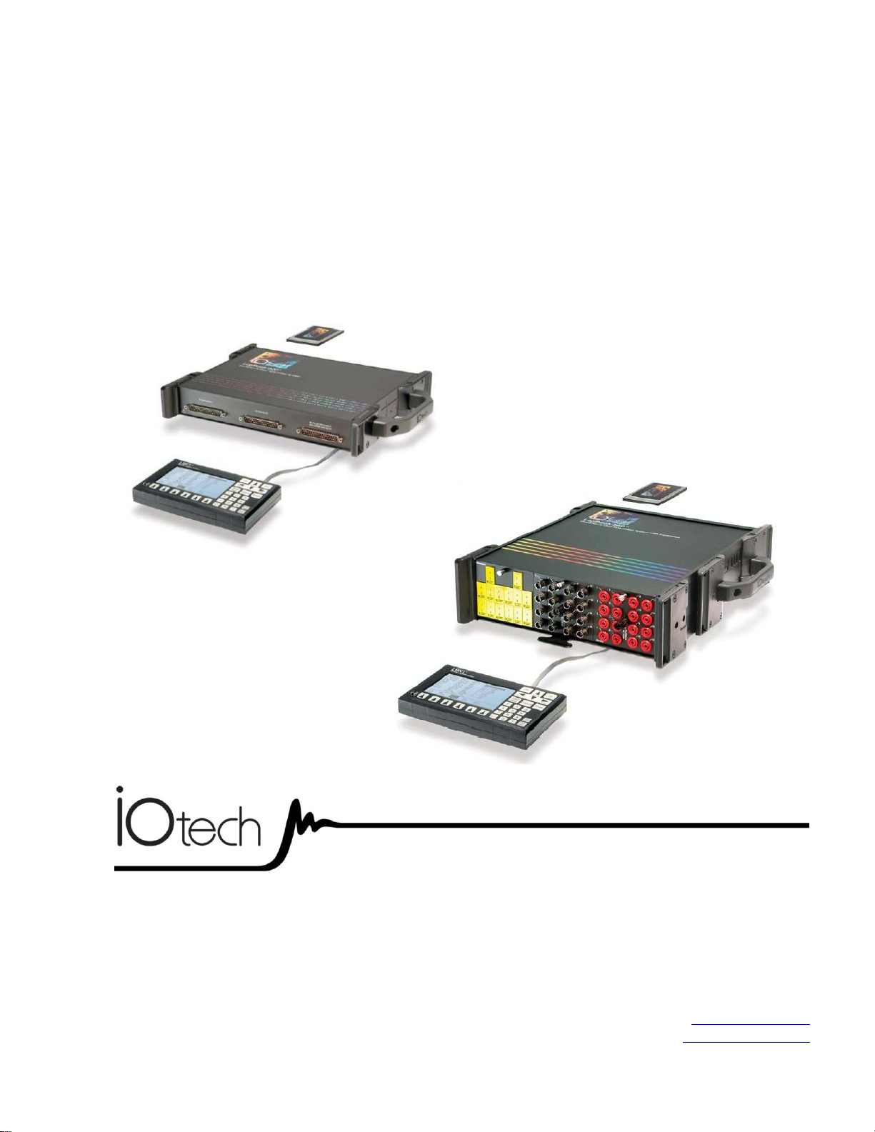
LogBook/300 & 360
p/n 461-0901 rev 7.0
*372180C-01*
372180C-01
Measurement Computing
10 Commerce Way
Norton, MA 02766
(508) 946-5100
Fax: (508) 946-9500
info@mccdaq.com
www.mccdaq.com
LogBook/300 & /360
Stand-alone, Intelligent PC-Based
Data Acquisition Systems
USER’S MANUAL
Page 2

This page is intentionally blank.
Page 3
Warranty Information
Contact Measurement Computing by phone, fax, or e-mail in regard to warranty-related issues:
Phone: (508) 946-5100, fax: (508) 946-9500, e-mail: info@mccdaq.com
Many Measurement Computing products carry the CE marker indicating they comply with the safety and emissions
standards of the European Community. When applicable these products have a Declaration of Conformity stating which
specifications and operating conditions apply. You can view the Declarations of Conformity at
www.mccdaq.com/legal.aspx (CE Information page).
Refer all service to qualified personnel. This caution symbol warns of possible personal injury or equipment damage
under noted conditions. Follow all safety standards of professional practice and the recommendations in this manual.
Using this equipment in ways other than described in this manual can present serious safety hazards or cause equipment
damage.
This warning symbol is used in this manual or on the equipment to warn of possible injury or death from electrical
shock under noted conditions.
This ESD caution symbol urges proper handling of equipment or components sensitive to damage from electrostatic
discharge. Proper handling guidelines include the use of grounded anti-static mats and wrist straps, ESD-protective bags
and cartons, and related procedures.
This symbol indicates the message is important, but is not of a Warning or Caution category. These notes can be of great
benefit to the user, and should be read.
In this manual, the book symbol always precedes the words “Reference Note.” This type of note identifies the location
of additional information that may prove helpful. References may be made to other chapters or other documentation.
Tips provide advice that may save time during a procedure, or help to clarify an issue. Tips may include additional
reference.
Limitation of Liability
Measurement Computing cannot be held liable for any damages resulting from the use or misuse of this product.
Copyright, Trademark, and Licensing Notice
All Measurement Computing documentation, software, and hardware are copyright with all rights reserved. No part of
this product may be copied, reproduced or transmitted by any mechanical, photographic, electronic, or other method
without Measurement Computing’s prior written consent. IOtech product names are trademarked; other product names, as
applicable, are trademarks of their respective holders. All supplied IOtech software (including miscellaneous support
files, drivers, and sample programs) may only be used on one installation. You may make archival backup copies.
CE Notice
Warnings, Cautions, Notes, and Tips
Specifications and Calibration
Specifications are subject to change without notice. Significant changes will be addressed in an addendum or revision to
the manual. As applicable, the hardware is calibrated to published specifications. Periodic hardware calibration is not
covered under the warranty and must be performed by qualified personnel as specified in this manual. Improper
calibration procedures may void the warranty.
Page 4
CAUTION
Using this equipment in ways other than described in this manual can cause
personal injury or equipment damage. Before setting up and using your
equipment, you should read all documentation that covers your system.
Pay special attention to Warnings and Cautions.
Note:
During software installation, Adobe
®
PDF versions of user manuals will automatically
install onto your hard drive as a part of product support. The default location is in the
Programs group, which can be accessed from the Windows Desktop. Initial
navigation is as follows:
Start [Desktop “Start” pull-down menu]
⇒ Programs
⇒ IOtech LogBook Software
You can also access the PDF documents directly from the data acquisition CD by using
the <View PDFs> button located on the opening screen.
Refer to the PDF documentation for details regarding both hardware and software.
®
A copy of the Adobe Acrobat Reader
is included on your CD. The Reader provides
a means of reading and printing the PDF documents. Note that hardcopy versions of
the manuals can be ordered from the factory.
Your order was carefully inspected prior to shipment. When you receive your system, carefully
unpack all items from the shipping carton and check for physical signs of damage that may have
occurred during shipment. Promptly report any damage to the shipping agent and your sales
representative. Retain all shipping materials in case the unit needs returned to the factory.
iv
929196 LogBook User’s Manual
Page 5

Manual Layout
Chapter 1 – An Introduction to LogBook discusses LogBook basics and highlights operational features.
The last part of the chapter contains product specifications.
QS300 – LogBook/300 Quick Start Guide
QS360 – LogBook/360 Quick Start Guide
(Includes Installation Procedure)
(Includes Installation Procedure)
Chapter 4 – System Expansion discusses the expansion of LogBook systems in regard to LBK and
DBK options. Power considerations and pinouts for P1, P2, and P3 DB37 connectors are also
included.
DBK Basics – discusses option cards and modules (DBKs) that can be used to enhance and expand data
acquisition systems. Note that DBK Basics is not a chapter, but an independent document that is
applicable to this user’s manual, as well as others.
Chapter 5 – LBK and other non-DBK Options discusses the RS-422/485 Communications Card,
memory expansion, remote LogBook Terminal, four-channel Digital-to-Analog Output card, and
three options regarding a remote on/off switch and LED indicator.
Chapter 6 – GPS and Serial Device Data Collection discusses the LogBook/360 support for the Global
Positioning System (GPS).
Chapter 7 – Using Modems and the Upload Scheduler provides instruction for communicating with
remote LogBooks via modem. The chapter also discusses the independent Upload Scheduler
application which can be used to configure events to initiate data uploads for one or more LogBooks.
Chapter 8 - CE Compliance pertains to CE standards and conditions relevant to LogBook systems.
LogView
- is a reference document for the “out-of-the-box” data acquisition software.
Appendix A – A Supplement to the HopNet 10 Series Wireless Modems User’s Manual. This appendix
only applies to users of Cirronet’s HopNet 10 Series Wireless Modems. In regard to using other
modems with LogBook refer to chapter 7.
Error Codes – two lists of error codes, one for LogView software and another for LogBook hardware.
Dimensional Drawings – Contains basic dimensional drawings that apply to several data acquisition
products, including LogBook/300, LogBook/360, and DBK options.
Glossary
Reference Notes:
During software installation, Adobe
installed onto your hard drive as a part of product support. The default location is in the
Programs directory, which can be accessed from the Windows Desktop.
®
PDF versions of user manuals are automatically
For detailed information regarding specific DBKs, refer to the DBK Option Cards and
Modules User’s Manual PDF. Each DBK section includes device-specific hardware and
software information. The document includes a chapter on power management.
Check the README.TXT file for information that may not have been available at the
time this manual went to press.
LogBook User’s Manual 989492 v
Page 6

This page is intentionally blank.
vi 989492 LogBook User’s Manual
Page 7

Table of Contents
Chapter 1 – An Introduction to LogBook
LogBook Basics……1-1
What are LogBooks? ….. 1-1
Front and Rear Panels……1-2
Highlight of Features …… 1-3
LogBook/300 Block Diagram …… 1-4
LogBook/360 Block Diagram …… 1-5
The Use of PC-Cards with LogBook…..1-6
System Software……1-7
Operational Features……1-9
Data Acquisition, An Overview……1-9
LogBook System File [Must be on the PC-Card!] ……1-10
Communications……1-10
Triggering and Scan Timing……1-11
Scan Rate Limitations……1-11
Use of Outputs to Alarm and Control……1-13
Acquisition……1-13
Data Storage and Retrieval……1-13
Specifications …. 1-15
QS300 – LogBook/300 Quick Start Guide (Includes Installation Procedure)
QS360 – LogBook/360 Quick Start Guide (Includes Installation Procedure)
Chapter 4 – System Expansion
Expansion and Enhancement Options…..4-1
What are LBK Options?……4-1
What are DBK Options?……4-2
Power Options …… 4-3
Other Options …… 4-3
Considerations …… 4-4
DBK Configuration ….. 4-4
Dimensional and Environmental Factors……4-4
Mechanical Setup Options……4-5
P1, P2, P3 Port Connectors……4-6
LogBook User’s Manual 989492 vii
Page 8

DBK Basics
Chapter 5 – LBK and other non-DBK Options
LBK Options, Location Reference …… 5-1
LBK/COM/422/485 …… 5-2
LBK/MEM1-U, Expanded Memory (16 MB Upgrade) ……5-3
LBK1, Remote LogBook Terminal …… 5-4
LBK2, Four Channel, Digital-to-Analog Output …… 5-9
Remote On/Off Switch and LED Indicator Options …… 5-11
Chapter 6 – GPS and Serial Device Data Collection
Chapter 7 – Using Modems and the Upload Scheduler
Chapter 8 - CE-Compliance
Overview …… 8-1
CE Standards and Directives …… 8-1
Safety Conditions …… 8-2
Emissions/Immunity Conditions …… 8-3
CE Enhancements …… 8-3
Edge Guards for DBK5, DBK8, & DBK44 …… 8-3
DBK41/CE …… 8-4
BNC Connectors for CE Compliance …… 8-4
LogView
Understanding LogView…… LV-1
Modes of LogView Operation…… LV-2
LogView Features and Capabilities… LV-5
Software User-Interface…… LV-5
File Management...... LV-8
Procedures…… LV-12
Flowchart of a Simple Acquisition..…. LV-13
Using an Attached LogBook…… LV-13
Using LogBook “Unattached”…… LV-15
Simple Data Logging…… LV-15
Setting Up DBK Cards…… LV-17
Using Multiple Timebases…… LV-18
Using Digital 2-Point Calibration…… LV-21
Using Digital Outputs As Alarms…… LV-22
Using Exception Capturing…… LV-24
Menu Descriptions…… LV-25
File Menu…… LV-25
View Menu…… LV-30
Hardware Configuration…… LV-30
Analog Input Channel Configuration…… LV-31
Digital and Counter Input Channel Configuration…… LV-35
Output Channels Configuration…… LV-36
Serial / GPS Channels (LogBook/360 Only)…… LV-37
Calculated-Channel Configuration…… LV-37
Acquisition Configuration…… LV-43
Preferences…… LV-46
Note: Use of the following
Authorization Code will enable
complete LogView functionality:
ED7B55484273
viii 989492 LogBook User’s Manual
Page 9

Device Menu…… LV-48
Select PC-Card...... LV-48
Select LogBook…… LV-48
Attach…… LV-48
Break…… LV-48
Arm Acquisition…… LV-48
Stop Acquisition…… LV-48
LogBook Monitor …… LV-49
Explorer…… LV-50
Tools Menu…… LV-51
Convert Binary Data…… LV-51
Merging Binary Data…… LV-53
View Data …… LV-54
Indicators Menu…… LV-55
Bar Graph Meters…… LV-55
Analog Meters…… LV-55
Digital Meters…… LV-56
Meters Configuration…… LV-56
Enable Input Reading Column…… LV-58
Start (or Stop) All Indicators…… LV-58
Appendix A – Supplement to the HopNet 10 Series
Wireless Modems User’s Manual
Error Codes
Dimensional Drawings
Glossary
LogBook User’s Manual 989492 ix
Page 10

This page is intentionally blank.
x 989492 LogBook User’s Manual
Page 11
An Introduction to LogBook 1
LogBook Basics……1-1
What are LogBooks? ….. 1-1
Front and Rear Panels……1-2
Highlight of Features …… 1-3
LogBook/300 Block Diagram …… 1-4
LogBook/360 Block Diagram …… 1-5
The Use of PC-Cards with LogBook …. 1-6
System Software……1-8
Operational Features……1-8
Data Acquisition Overview……1-8
LogBook System File [Must be on the PC-Card!] ……1-9
Communications……1-10
Triggering and Scan Timing……1-11
Scan Rate Limitations……1-11
Use of Outputs to Alarm and Control……1-13
Acquisition……1-13
Data Storage and Retrieval……1-13
Specifications …… 1-15
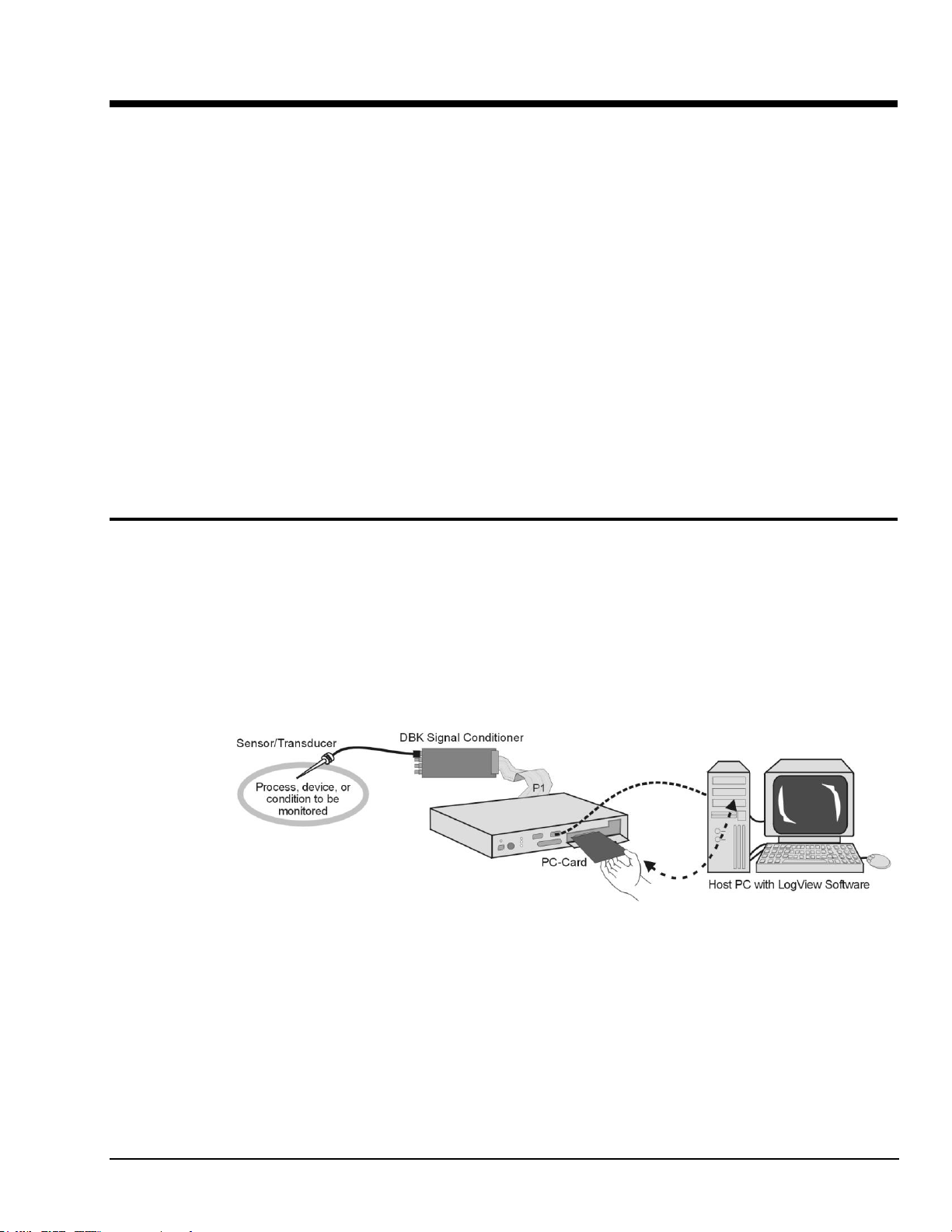
LogBook/300, Simple System Setup
LogBook Basics
What are LogBooks?
LogBook/300 and LogBook/360 are PC-based data acquisition systems that can work in a stand-alone
mode (no PC present), or linked to a PC. They combine onboard intelligence with a removable PC-Card
that stores the configuration file and the collected data. LogBooks have many options, most of which are
detailed in the LBK chapter, and in the DBK Option Cards and Modules document. Note that the PC link
can be by serial or parallel port.
LogBook User’s Manual 969591 An Introduction to LogBook 1-1
The PC-Card holds the configuration file [created by LogView]. The file tells LogBook how to perform a
particular acquisition. The PC-Card also holds the acquired data files. The PC can upload to or download
from the PC-Card by cable if the PC is attached to LogBook, or by physical transport of the PC-Card from
one unit to the other. Multiple configuration files and multiple PC-Cards allow the system to handle
complex data acquisition environments with a large number of data-files.
Page 12
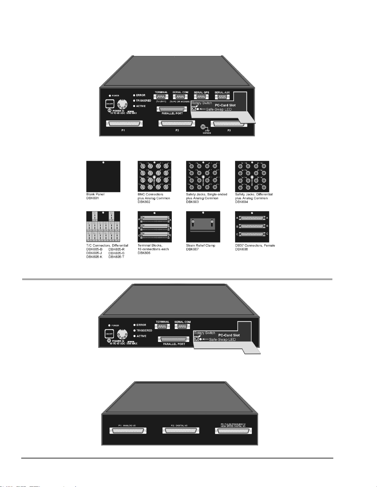
Front and Rear Panels
LogBook/360, Front Panel
LogBook/360, Terminal Panels (A combination of 3 make up the rear panel)
LogBook/300, Front Panel
Note: In earlier models, the PC-Card Door has a right-edge hinge (not shown).
LogBook/300, Rear Panel
Note: Descriptions of panel items appear on the following page.
1-2 An Introduction to LogBook 969591 LogBook User’s Manual
Page 13

LogBook/360 panel items are listed in the following table. Note that LogBook/300 panel items are the same as those on
the 360, except as called out in the following bulleted list:
Slight differences in the overlay.
P1, P2, and P3 appear on LogBook/300’s rear panel.
LogBook/300 has no SERIAL GPS connection.
LogBook/300 has no SERIAL AUX connection.
LogBook/300 has no CHASSIS grounding post.
LogBook/300 does not make use of Terminal Panels.
Switches
ON/OFF
Depressing the push-button switch turns the power on.
(interior rotary switch)
PC-Card door provides access to a rotary switch to set device address when used in an RS-485 network.
Connectors
POWER IN
This locking DIN5 input connector accepts +10 to +45 VDC.
PARALLEL PORT
This DB-25 plug is a parallel port connector to a host PC (set to ECP mode)
TERMINAL PORT (TO LBK1)
This DB-9 socket is a serial port connector for the LBK1 remote control panel (user-interface terminal).
SERIAL COMM
(TO PC OR MODEM)
This DB-9 male serial COM port connects to a host PC or modem.
SERIAL GPS
(LogBook/360 Only)
LogBook/360 only. This DB-9 male serial port option connects to a Global Positioning System.
SERIAL AUX
(LogBook/360 Only)
LogBook/360 only. This DB-9 male serial port option connects to optional auxiliary devices.
P1 - ANALOG I/O
Provides 16 analog input channels, 3 TTL inputs, and various signals for driving expansion cards.
P2 - DIGITAL I/O
Provides 3 8-bit TTL programmable I/O ports and external interrupt input.
P3 - PULSE FREQUENCY /
HIGH-SPEED DIGITAL I/O
Provides 4 16-bit counters, 4 analog outputs, and 16 high-speed digital I/O.
(PC-Card door, no label)
Door provides access to PCMCIA connector—for removable PC-Card memory devices.
Indicator LEDs
POWER
LED lights when power is applied to LogBook and the power switch is depressed into the ON position.
ERROR
LED lights steady ON when a routine error occurs (e.g. disk full).
LED flashes for fatal errors; refer to Hardware Errors near the end of the manual.
No data can be acquired until the error is cleared.
TRIGGERED
LED lights after trigger event and during an A/D scan sequence.
ACTIVE
LED lights to show that LogBook is ready to begin a scan at the next trigger event.
Safe-Swap Light
(interior green LED)
LED lights when it is safe to swap PC-Cards.
Highlight of Features
LogBooks can be left unattended for long testing periods and used in environments not suitable for PCs.
With the use of PC-Cards, one PC can support several LogBooks. Other LogBook features include:
Onboard processor capable of real-time data reduction and system control in stand-alone mode
Non-volatile storage of configuration files and samples via removable, transportable PC-Cards
4 MB RAM onboard, expandable to 16 MB
100 kHz 16-bit Analog-to-Digital Conversion
8 differential, 16 single-ended inputs; expandable to 256 input channels via DBK cards
7 gain/input ranges, unipolar and bipolar
40 digital I/O lines, expandable to 208
4 pulse-counting inputs
Gain and unipolar/bipolar settings are programmed in real time (10 µs max)
Scan-sequence memory (1024 analog channels plus 128 digital channels)
for any combination of channels/gains
Input power: 10 to 45 VDC (AC adapter included)
LBK options
DBK options
LogBook User’s Manual 969591 An Introduction to LogBook 1-3
Page 14
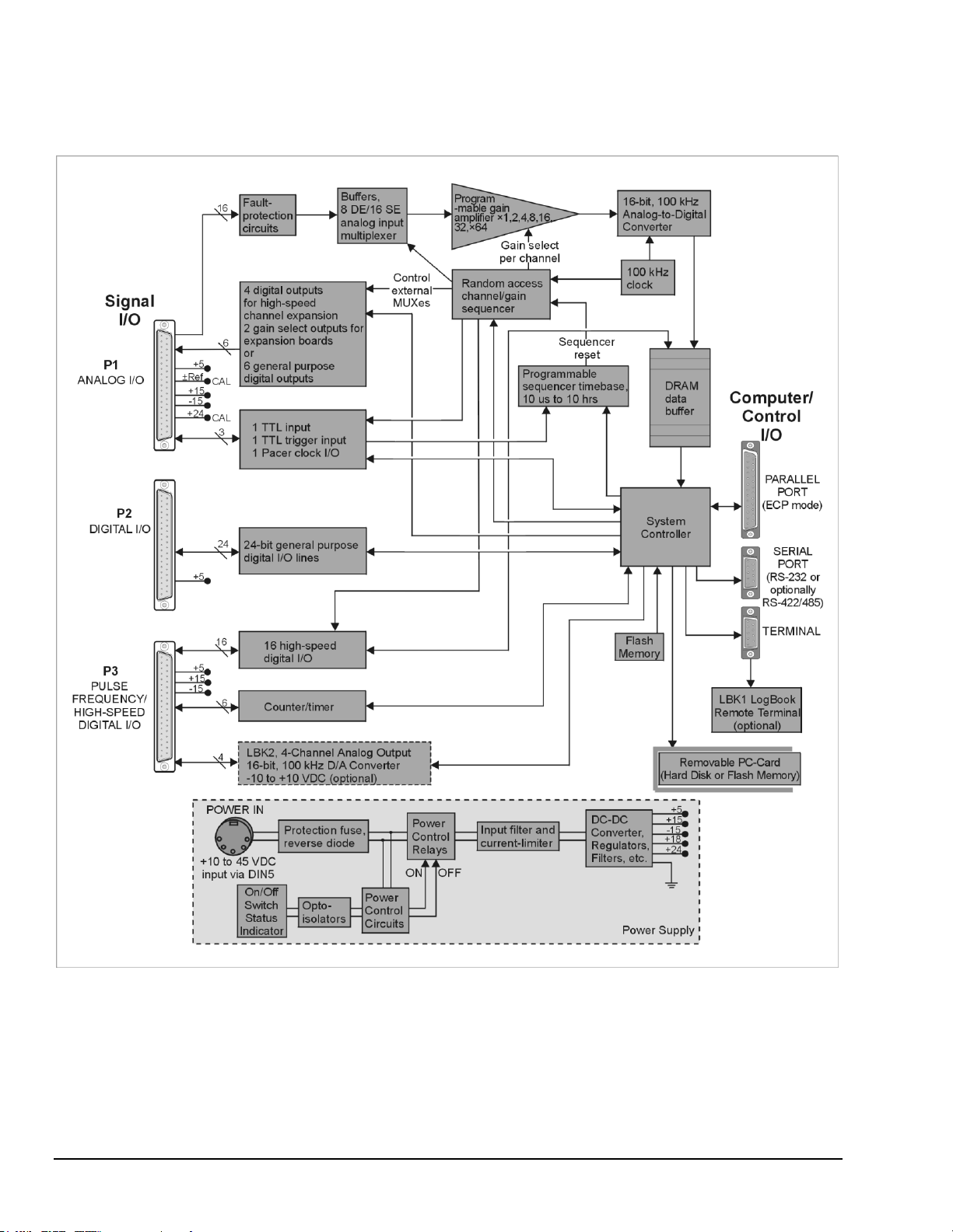
LogBook/300 Block Diagram
1-4 An Introduction to LogBook 969591 LogBook User’s Manual
Page 15
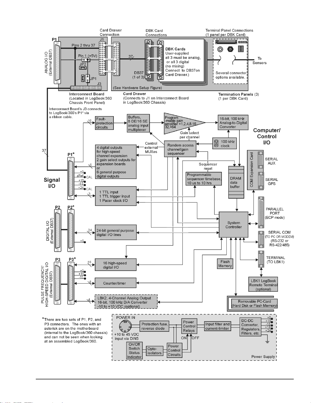
LogBook/360 Block Diagram
LogBook User’s Manual 969591 An Introduction to LogBook 1-5
Page 16

The following components are represented in the previous block diagrams. Certain items apply only to
LogBook/360, as noted.
Removable PC-Card. A 12-520 MB capacity holds the software, operating system, user
configurations and the acquired data. The PC-Card is at the center of LogBook operations.
A PC-Card [pre-programmed by LogView] ensures an unattached LogBook comes up properly.
Power Supply. The internal power supply accepts an input of 10 to 45 VDC and supplies filtered
regulated voltages to its internal circuits and to accessories connected via P1/2/3. An external
AC to-DC adapter for all standard voltages is included with the system.
System Controller. A microprocessor chip is used within LogBook with either 4 MB (standard) of
RAM or 16 MB (optional). A field-upgradeable 512 KB Flash memory is used to store the system
startup code, self-diagnostics, and Field Programmable Gate Array (FPGA) configuration. The
FPGA controls every LogBook operation, including real-time control. By using Internal flash
memory instead of EPROMs, field upgrades of virtually all functions [including FPGA circuitry] are
possible. Most software will be read from the disk drive.
Analog Input via P1. 16 main channels that can each accommodate 16 sub-channels via
multiplexing for a total of 256 analog input channels. Fault protection and buffer circuits prevent
overloads and cross-channel noise due to impedance mismatch.
A/D Converter. The A/D converter uses 16-bit resolution @ 100 kHz sample rate.
Digital I/O. 16 high-speed digital inputs via P3, three 8-bit TTL programmable I/O ports via P2,
three TTL inputs via P1. Note that LogBook/360 has P1, P2, and P3 connectors on the motherboard
that are connected [by ribbon cable] to secondary P1, P2, and P3 connectors [located on the chassis
front panel]. LogBook/300’s P1, P2, and P3 are located on the rear panel.
LBK2 Analog Output (optional): This option provides four channels of analog output,
16-bit @ 100 kHz @ ±10 VDC.
LogBook/360 only, Interconnect Board, Card Drawer (for three DBK cards), and
three Terminal Panels.
Computer/Control/I/O – Includes: PARALLEL PORT (ECP Mode), SERIAL PORT (for RS-232
or RS-422/485), TERMINAL PORT (for LBK1 LogBook Remote Terminal option). In addition, for
LogBook/360 only, there is a COM Expansion Card with two serial ports (SERIAL AUX and
SERIAL GPS). These two ports are for connecting auxiliary serial devices, such as a Global
Positioning System.
The Use of PC-Cards with LogBook
After the initial setup, you can interact with LogBook via PC-Cards. A safe-swap LED (inside the PC-Card
access door) lights when it is safe to change PC-Cards. You can also interact with LogBook using the
LBK1 Remote Terminal Panel option (discussed in the LBK chapter). The LBK1 option provides limited
LogBook control without use of the LogView program. As can be seen from the following PC-Card
Compatibility information, some PC-Cards should be avoided in regard to use with LogBook.
Note: during operation, LogView is the primary system interface for control and configuration.
PC-Card Compatibility with LogBook Operation
To work properly, the LogBook requires compatible PC-Card memory. You can purchase 100%
compatible cards through your LogBook sales representative. If you prefer to buy your card from another
source, make sure it is an ATA-style memory card. Also, make sure the card's memory capacity is sufficient
for your purpose.
You can change PC-Cards to load setup files, replace full cards, or transport data to an unattached PC.
When the PC-Card door is opened, a detector starts a preparatory routine to clean up files on the installed
disk. Within a few seconds, a green LED indicates it is safe to swap PC-Cards. Swapping should be done
quickly to prevent gaps in the recorded data. 4 MB RAM provides about
10 seconds at 100 kHz and 1.75 minutes at 10 kHz. 16 MB RAM provides over a minute at 100 kHz and
about 12 minutes at 10 kHz for one-channel scans.
1-6 An Introduction to LogBook 969591 LogBook User’s Manual
Page 17
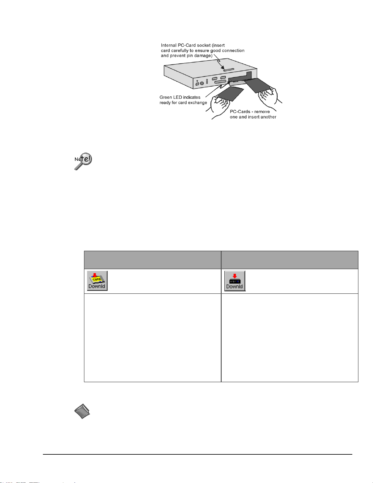
Swapping PC-Cards in a LogBook/300
Note: Some models have PC-Card doors with right-edge hinges (not shown).
Swapping time is measured from when the door opens. Keep door closed unless you are
in the process of swapping cards.
PC-Cards must be pre-configured by LogView—if anticipating the need for multiple cards,
download the exact SAME ACQUISITION SETUP FILE to each PC-Card.
The PCMCIA slot accepts a Type I, II, or III hard-disk card or ATA flash-memory
solid-state card.
Download Method I:
PC-Card in Computer’s PC-Card Slot
Download Method II:
PC-Card in LogBook’s PC-Card Slot
LogView’s <Download> button as it appears
when a PC-Card in the PC can accept a
download.
LogView’s <Download> button as it appears
when a PC-Card in the LogBook can accept a
download.
1. Insert a formatted PC-Card into the computer’s
PC-card slot.
2. Run LogView.
3. From LogView’s Device pull-down menu choose
―Select PC Card.‖
4. Select the applicable PC-Card drive from the
resulting pull-down list.
5. Click LogView’s <DownLoad> button.
For this method the LogBook must be connected to
the PC’s serial* or parallel port.
1. Insert a formatted PC-Card into LogBook’s
PC-Card slot.
2. Run LogView.
3. From LogView’s Device pull-down menu.
choose ―Select LogBook.‖
4. Click on the desired LogBook.
5. Click the <Attach> button.
6. Click LogView’s <DownLoad> button.
Reference Notes:
Additional information regarding PC-Cards can be found in the chapter sections entitled,
Data Acquisition Overview (page 1-8) and LogBook System File (page 1-9).
For information regarding LogView, refer to the independent LogView section of this manual.
How to Download a Configuration to a PC-Card
The download of a configuration to a PC-Card can be done in either of two ways, both of which make use
of LogView’s <Download> button. One method is to download the file to the PC-Card while it is installed
in a card slot on the PC. The second method is to download the file while the PC-Card is in a LogBook. In
that scenario the LogBook must be connected to the serial or parallel port of a PC. A brief description of
both methods follows. In both cases the filename will be the same as the LogView setup name.
*Note: For method II only, if downloading a modem configuration, LogBook’s communication cable must
connect to a parallel port on the PC. Otherwise parallel or serial communications will do.
LogBook User’s Manual 969591 An Introduction to LogBook 1-7
Page 18

System Software
Although LogBook can read volts directly, many sensor types still require signal
conditioning before they can be correctly interpreted.
LogBook software includes LogView, Upload Scheduler (optional) and a post acquisition data analysis
application such as eZ-PostView. A synopsis of each application follows.
LogView is a ready-to-use Windows-based program for data acquisition and logging. The program
Upload Scheduler is an application that exists as part of the LogBook/Modem option. Upload
Post Acquisition Data Analysis programs provide a means of viewing and analyzing data via
provides a means of selecting channels, gains, transducer types, and various parameters. After setting
up the configuration on the PC, you must download the configuration file to LogBook’s PC-Card.
LogBook then uses the PC-Card to start the pre-configured acquisition. During an acquisition,
LogView can display channel values on its Graphical User Interface in the form of a spreadsheet,
bargraph, analog meter, or digital indicator. LogBook data can be uploaded to your PC in various
data formats (Excel™, SnapMaster™, MATLAB™, DASYLab™, Lotus®, Quattro, and ASCII) for
compatibility with virtually all post-acquisition analysis software.
Scheduler allows you to configure upload events for one or more LogBooks. A scheduled event can
be configured to execute one time, or periodically, with no post-configuration intervention by the
user. The Upload Scheduler is detailed in chapter 7, Using Modems and the Upload Scheduler.
interactive graphics. Refer to the document module for detailed information. The post data analysis
programs are discussed in an independent document. PDF versions of the documents are loaded on
to your computer’s hard drive during software installation. The default location for the files is the
Programs group, which is accessible from the Windows Desktop.
Operational Features
Data Acquisition Overview
Note: Acquired data is signal-conditioned before it is logged (recorded by LogBook). The data can be
post-processed via analytical programs.
A Sensor/Transducer reacts to a physical quantity (such as stress, strain, frequency, temperature,
acceleration, light intensity, etc) and encodes that quantity into an analogous electrical signal. A wide
variety of transducers produce signals that vary in type and strength—some generate a voltage; others alter
an electrical property. As the measured condition changes, the analog sensor signal can vary directly or
inversely and in a linear or non-linear way.
The Signal Conditioner changes the raw transducer signal into a voltage for use by
LogBook’s Analog-to-Digital Converter (ADC). Depending on signal quality, several steps may be
involved (e.g., linearization, isolation of high voltages, amplification of weak signals, attenuation of strong
signals, filtering of noise and irrelevant frequencies, differential voltage measurement, simultaneous sampleand-hold, and pulse/current-to-voltage conversions). DBK option modules are designed for conditioning a
particular type of transducer signal. The signal conditioner’s output voltage range is ―normalized‖ to a
user-selected range for the measured values.
Note: Multi-channel DBKs can multiplex several input signals into one of LogBook’s 16 main inputs.
Multiplexing up to 16 analog channels for each LogBook main channel allows system expansion
up to 256 analog input channels.
1-8 An Introduction to LogBook 969591 LogBook User’s Manual
Page 19

LogBook’s onboard microprocessor and PC-Card allow it to operate independent of a host PC.
The file logbook.sys is LogBook’s operating system. Without it, LogBook will not work.
In fact, if the logbook.sys file is not on LogBook’s internal PC-Card, the LogBook will not
power-on.
Failure to upgrade to the current release version of logbook.sys can result in software
glitches. This problem can be resolved by reformatting the PC-Card using Windows
Explorer’s File/Format feature, and then reinitializing the PC-Card.
Functionally, LogBook can perform:
Analog-to-Digital Conversion. The ADC changes a conditioned analog signal to a corresponding
digital value. LogBook’s 16-bit ADC uses 65,536 numbers (216) to quantify values within the
specified range and gain. Each input channel’s buffer amplifier ensures constant input impedance.
The buffers also eliminate any noise effects from multiplexing of the input signals.
Acquisition Control. The microprocessor controls the data acquisition by managing trigger
conditions, gains, offsets, scan sequencing, and data formatting. LogBook can continuously collect
information, or be used for exception-capturing (with triggers). Pre-trigger and post-triggers allow
for capture of specific data, thus making more efficient use of memory.
Analog and Digital I/O. With the standard digital I/O, standard analog input, and the optional
analog output board, LogBook can perform virtually any data acquisition task as well as more
complex tasks for alarm and control systems.
Data Logging. Data can be saved in one of several formats and later downloaded to a PC.
Communication with PC. LogBook provides for serial and parallel port communication. In the
stand-alone mode, the PC-Card must be manually transported between the PC and LogBook.
The PC-Card is a memory device (rotating or flash, PCMCIA types I, II, or III)) that holds the system
software and the acquired data in multiple formats. System software includes the configuration file that
directs a specific acquisition and LogBook’s operating system. The PC-Card as programmed in LogView
allows LogBook to operate without PC intervention if so desired. LogView can configure a PC-Card in
LogBook if the PC and LogBook are electronically connected via serial or parallel port. In a stand-alone
mode, the PC-Card must be physically transported between a PC with LogView and one or more LogBooks
for uploading and downloading. Using a 500-Mbyte PC-Card, for example, you can store up to 250 million
samples in non-volatile memory; that equates to more than forty minutes of recording time on one channel
at the full 100 kHz acquisition rate. For continuous data collection, PC-Cards can be swapped while the
acquisition is taking place. As one card becomes nearly full, it can be removed and another card inserted
without causing a gap in the acquired data.
The user’s PC (typically a laptop or desktop) runs the supplied LogView software. LogView’s userinterface includes a virtual instrument panel with meters and controls to fit various applications. Through
LogView you can configure the system, apply further data processing, or manage multiple LogBooks.
LogView stores data in a conventional format so that other software can use the acquired data for analysis,
control, alarms, reporting, etc.
Note: The PC can be attached to LogBook via a serial or parallel connection; alternatively in the stand-
alone mode, the PC can be unattached and communicate with LogBook via a PC-Card that is
manually transferred between the PC and LogBook.
LogBook System File [ Must be on the PC-Card! ]
After software is installed [as discussed in the Quick Start sections] the 500-KB logbook.sys file will
reside in the LogView folder (on the hard drive of the host PC). To be used by a LogBook, logbook.sys
must have already been downloaded to the PC-Card, which resides inside LogBook.
Downloading. When LogView downloads the *.lvc acquisition setup file to a PC-Card, it checks to see if
the current release version of logbook.sys is already on the PC-Card. If so, fine; if not, logbook.sys
must also be downloaded to the PC-Card. Thus, downloading to a PC-Card that is being used for the first
time will take longer than subsequent downloads.
LogBook User’s Manual 969591 An Introduction to LogBook 1-9
Page 20

Due to the file size and relative transfer time, insert first-time PC-Cards into the PC’s card
socket rather than LogBook’s. Downloading via the PC’s socket takes only a few seconds;
however, using LogBook’s socket and a communications channel will take much longer
(about 7 minutes at 9600 bps).
Because LogBook needs the logbook.sys file to become operational after loosing power
(due to an outage or being turned off), keep the logbook.sys file on all PC-Cards that will
be used for data storage.
Regarding the logbook.sys file and Power Loss. After LogBook is started, it can store data to a
PC-Card that does not have the logbook.sys file. However, in this case if LogBook loses power it will
not be able to restart! LogBook will restart when powered-on with a PC-Card that does have the
logbook.sys file.
Communications
Protocols
LogBook uses only standard, supported, widely available communication channels to minimize devicedriver development. The messages transmitted over these channels are also standard: human-readable
ASCII for commands and status, and standard file-transfer protocols (such as X-modem) for block data
transfers. The messages and protocols are independent of the choice of communication channel, except
when a channel explicitly requires a different protocol (such as FTP over TCP/IP). The use of such
standards makes LogBook easier to use and extend.
To implement these standards, LogBook includes a command parser and conversion software to convert
measured voltages into physical measurements such as temperature, force, or acceleration. This software is
used for monitoring transducer measurements, both at the PC and the LBK1. LogBook can return all data
as physical quantities and/or raw voltage measurements.
Large blocks of raw or converted data (such as entire acquisitions or a set of consecutive scans) are
transferred as binary files, using file-transfer protocols. Smaller blocks (such as individual readings or
scans) are transferred in readable ASCII.
Parallel Port – ECP Mode
LogBook includes an ECP parallel port for high-speed local communication with a PC in the ECP mode
(the only supported protocol is ECP). Your PC mode may need to be changed in its BIOS or in the
Window Settings—consult your PC’s documentation or the PC’s manufacturer as needed.
Serial Port
LogBook includes an RS-232 (RS-422/485 optional, call factory for availability) serial port supporting both
point-to-point and multi-drop remote communication.
Other Communication Channels
The serial communication protocols are standard so non-PC hosts can communicate with LogBook. The
use of printable ASCII for commands and status and the use of standard file-transfer protocols make it
practical to add additional ports such as USB, IEEE 488, TCP/IP. Consult factory for availability of these
communication options.
1-10 An Introduction to LogBook 969591 LogBook User’s Manual
Page 21

Triggering and Scan Timing
Reference Note: For information on defining triggering conditions through LogView, refer
to the Acquisition Configuration text and screen shots, which are provided in the LogView
document module.
If data collection is desired only under specific conditions, you can specify appropriate trigger conditions.
By defining a trigger, pre-trigger, and post-trigger, you can collect data surrounding a specific event. This
event can be an absolute time or a defined condition such as a particular analog channel measuring a certain
quantity. If a calculated channel is chosen as the trigger source, you have greater flexibility in defining the
trigger based on multiple inputs and conditional logic. An auto re-arm feature allows many successive
acquisitions to take place automatically, with each acquisition using the same settings.
LogBook can be triggered by several types of sources, including analog and digital triggering, multi-step
triggering, multi-channel triggering, time-of-day triggering, and manual trigger. The manual trigger can be
implemented in the following ways:
With a computer attached, you can trigger LogBook from LogView’s LogBook Monitor window.
Without a computer, you can use a manual trigger switch by attaching it to the TTL trigger input
(pin 25, on P1).
With a logic device you can engage the TTL trigger on P1’s pin 25, as programmed.
Without a computer, you can use the LBK1’s manual trigger button.
LogBook time-of-day clock has 1/256-second resolution for data-logging applications where acquisitions
must be performed at specific times during the day. The time of occurrence of each acquisition and its
trigger are also recorded with the data. The scan-to-scan timing may be set by a fixed-frequency pacer
clock. Or, an external clock can start each scan individually to allow the scan rate to track a variable-speed
event (such as engine revolutions).
Note: Time-stamping is done in 1/256-second units; but the absolute trigger is in 1-second units.
For data acquisition applications that include both fast and slow signals, multiple sample rates can be
configured. In the acquisition setup dialog box, a primary acquisition rate and divisors for up to 3 more
rates can be configured. Using multiple sample rates, fast signals like vibration can be sampled at a high
rate while slow signals like thermocouples are sampled at lower rates, optimizing the system’s storage
capacity.
Scan Rate Limitations
LogBook’s internal clock runs at 100 kHz, and this is the fastest scan rate possible with just one input
channel in the scan list and no outputs. As input, calculated, and output channels are added to the scan list,
the usable scan rate is correspondingly reduced. The system does not automatically compute an optimum
scan rate for you. However, LogView will generate an error message in the LogBook Monitor window if
timing problems occur, and the following sections explain such problems and how to solve them.
External TTL Trigger and Stop Events
An external TTL trigger can repeat before the trigger block completes; extra trigger signals will be ignored.
Likewise, multiple stop signals received before restarting the next scan will be ignored. Such ignored
signals are noted in the LogBook Monitor window as ―Losing Trigger Events‖ and ―Losing Stop Events‖.
Problems Arising From Too Fast a Scan Rate
If the user-specified scan rate does not provide enough time to complete the necessary tasks of the entire
scan list, various problems can occur. Bear in mind that LogBook places the highest priority on reading
input channels—it is primarily a data logger. Also realize that calculated and output channels are based on
input channels and come typically at the end of the scan list. Thus, if the scan rate is too fast and the next
sequence begins before the first is completed, the outputs may suffer. When outputs can’t keep up with the
inputs, possible consequences include:
Missing/late Outputs. The outputs are not updated in a timely fashion and may not represent their
sources in real time (LogBook Monitor error message is ―Outputs Deteriorating‖).
Missed Alarms. Digital alarm outputs may not be initiated soon enough—important alarms might
never go off.
LogBook User’s Manual 969591 An Introduction to LogBook 1-11
Page 22

Faulty Control. Control systems based on digital outputs or a DBK25 could fail if dependent on a
After running the acquisition, check the LogBook Monitor screen for error messages.
A list of Software and Hardware-related error codes is included near the end of the manual.
Output Signal Deterioration
fast critical response time.
Distorted Outputs. Analog outputs may appear to be "jaggy" or other distortions such as aliasing-
type errors.
Ideally, each output signal is based on one input, resulting in
an accurate output waveform. Factors such as scan rate,
number of output channels and calculated channels can
overload the system, resulting in one output signal for
multiple input scans. The resulting signal deterioration can
increase over time and shows up as a distorted and/or lagging
output signal. Such output errors can resemble aliasing
errors where output signals are distorted from their input
signals because the effective sampling frequency was not
high enough (see figure).
Solutions To Scan Rate Problems
To confirm a suspected timing problem with your acquisition, run the acquisition and then check:
The LogBook Monitor window in LogView for a corresponding error message.
Actual deterioration of outputs as described in the previous section.
To solve timing problems you may need to perform one or more of the following, in order of effectiveness:
Choose a slower scan rate, or change the trigger parameters.
Reduce the number of output channels.
Reduce the number or complexity of calculated channels.
Reduce the number of input channels.
Estimating an Optimum Scan Rate
Note: The scan rate can be measured as a frequency in Hz or kHz or as a period in ms or µs. These
two measures are reciprocals of each other; e.g., 1/100 kHz = 10 µs.
Processing input channels is LogBook’s highest priority; each input channel is collected at 10 µs. After all
the inputs are collected, LogBook performs the necessary calculations and then updates the enabled outputs.
The time to perform calculations and outputs varies with the type of calculation, and this makes it difficult
to predict the exact length of time required. Simple calculations are done much faster than functions for
non-linear thermocouples and RTDs or the use of logical and bitwise calculated channels. Output channels
can take from 100 µs to 300 µs; so for very approximate results, we’ll use 200 µs.
To estimate the maximum scan rate, use the following formula:
approximate scan period = (number of inputs × 10 µs) + (number of outputs × 200 µs)
If only 5 input channels are enabled, the scan period equals 50 µs with a frequency of 20 kHz. If one output
channel is added, the period becomes 250 µs with a frequency of 4 kHz.
1-12 An Introduction to LogBook 969591 LogBook User’s Manual
Page 23

Use of Outputs to Alarm and Control
Reference Note: For information on how LogView allows you to set outputs
based on user-defined conditions, refer to the LogView document module’s section entitled,
Calculated-Channel Configuration.
Replacement PC-Cards for use with LogBook must be pre-configured in order to store
acquisition data.
By careful setup of LogBook’s analog and digital outputs, you can control external devices and/or stimulate
the unit-under-test. Using LogView’s calculated channels, equations can be derived that can be used to
stimulate digital outputs for use as alarms or for on/off control. For example, the equation:
DIG1 = (CH1 - CH2) < 2
turns on digital output ―1‖ if the difference between channels 1 and 2 is less than 2.
The system’s four 16-bit analog outputs can also be used for controlling or stimulating external devices.
Using channel data derived from input channels and equations or canned waveforms, the analog outputs can
be updated at rates as high as 100 kHz.
Acquisition
A selected acquisition can be armed:
on command from the keypad or PC
at power-on, or
After an acquisition, LogBook may continue the same or begin a new acquisition. The new acquisition can
begin immediately, after a specified time interval, or at a specified time.
Data Storage and Retrieval
The quantity of acquired data can be reduced by block averaging or by decimation (skipping samples
without averaging). Then, data is placed onto the DOS-compatible disk drive using a proprietary format in
a DOS-compatible file. The acquisition setup name and a time stamp are also written to disk.
Post-processing programs can thereby correctly interpret the related data.
The PC can retrieve the acquired data through the serial or parallel port, during or after the acquisition.
Upon command from the PC, LogBook can switch to storing data into a new file. After the PC retrieves
data [from the first file], it can erase that file and reuse the space.
Note: Data is never erased without a specific command from the PC.
Data can also be retrieved from a PC-Card. LogBook copies enough information from the old card to the
new (replacement) card to make sure the current acquisition can continue on the replacement PC-Card.
LogBook User’s Manual 969591 An Introduction to LogBook 1-13
Page 24

1-14 An Introduction to LogBook 969591 LogBook User’s Manual
Page 25

General
Supply Voltage Range: 10 to 45.0 VDC
Power Consumption: 0.9 A @ 15 VDC
Operating Temperature: -40° to 140°F (-40°C to 60°C)
Storage Temperature: -40° to 176°F (-40°C to 80°C)
Humidity: 0 to 95% RH, non-condensing
PC-Card Memory: Standard ATA Type
LogBook/300:
Size: 8½ × 11 × 1¾ in. (216 × 279 × 44 mm)
Weight: 3.3 lb (1.5 kg)
LogBook/360:
Size: 14 × 11 × 3.5 in. (356 x 279 × 89 mm)
Weight: 7.3 lb (3.3 kg)
A/D Specifications
Type: Successive approximation
Resolution: 16 bit
Conversion Time: 10 µs
Monotinicity: No missing codes
Linearity: ±1 bit
Analog Inputs
Channels: 16 single-ended, 8 differential,
expandable up to 256 differential; singleended or differential operation is software
programmable.
Connector: DB37 male, P1
Maximum Overvoltage: -35 V, +45 V
Input Current:
Differential: 0.4 µA typical, 0.7 µA max
Single-ended: 0.2 µA typical, 0.35 µA max
Input Impedance:
10 M differential in parallel with 20 pF
5 M single-ended in parallel with 30 pF
Calibration: Digital software calibration
Channel-to-channel Crosstalk: 100 dB
Ranges: Unipolar/Bipolar operation is software-programmable
on a per-channel basis.
BIPOLAR
±10V
±5V
±2.5V
±1.25V
±0.625V
±0.3125V
±0.15625V
±(% Reading + µV)
0.015 + 500
0.015 + 500
0.015 + 300
0.015 + 250
0.015 + 150
0.020 + 150
0.050 + 100
UNIPOLAR
0 to +20V
0 to +10V
0 to +5V
0 to +2.5V
0 to +1.25V
0 to +0.625V
0 to +0.3125V
±(% Reading + µV)
0.015 + 500
0.015 + 500
0.015 + 300
0.015 + 250
0.015 + 150
0.020 + 150
0.050 + 100
Triggering
Analog Trigger:
Programmable Level Range: full range of
specified channel
Trigger to A/D Latency: 10 µs max
Digital Trigger:
Logic Level Range: 0.8 V low/2.2 V high
Trigger to A/D Latency: 10 µs max
Software Trigger:
Trigger to A/D Latency: Dependent on PC
Pre-Trigger: Up to 4 gig scans, depends on
PC-card memory
LogBook Specifications Specifications are subject to change without notice.
LogBook User’s Manual 969591 An Introduction to LogBook 1-15
Page 26

Sequencer
Randomly programmable for channel and gain and for
unipolar/bipolar (where applicable)
Depth: 1024 analog channels plus 128 digital
channels
Channel to Channel Rate: 10 µs/channel, fixed
Maximum Rep Rate: 100 kHz
Minimum Rep Rate: 10 hours
Expansion Channel Sample Rate: Same as on-board
channels, 10 µs/channel
General Purpose Digital I/O
24 I/O channels, expandable up to 192
Connector: DB37 male, P2
Device: 82C55
Maximum Input and Update Rate: 100 kHz
Output Voltage Levels:
Minimum “1" Voltage: 3.0 @ 2.5 mA sourcing
Maximum ”0" Voltage: 0.4 @ 2.5 mA sinking
Output Current:
Maximum Source Current: 2.5 mA
Maximum Sink Current: -2.5 mA
Input Voltage Levels:
Minimum Required “1" Voltage Level: 2.0 V
Maximum Allowed ”0" Voltage Level: 0.8 V
Output Float Leakage Current: 10 µA
High-Speed Digital I/O
Channels: 16 input lines
Connector: DB37 male, P3
Maximum Sampling Rate: 100K words/s
Input Low Voltage: 0.8 V max
Input High Voltage: 2.0 V min
Input Low Current: 10 µA
Input High Current: -10 µA
Frequency/Pulse Counter
Channels: 4, 16 bits per channel, cascadeable
Connector: DBK37 male, P3
Maximum Pulse Count: 32-bit binary (2 channels
cascaded)
Maximum Input Rate: 1 MHz
Input Voltage: -15 to +15 V
Threshold Voltage (Low): 0.8 V typical, 0.5 V min
Threshold Voltage (High): 1.6 V typical, 2.1 V max
Hysteresis: 400 mV min
Pulse Width (High or Low): 520 ns min
Input Impedance: 27 K pull-up to +5 V in
parallel with 50 pF
Frequency/Pulse Generator
Channels: 2, 16 bits per channel
Connector: DB37 male, P3
Frequency/Pulse Generating Mode: Input frequency
divided by
1 to 65,535
Input Low Voltage: 0.8 V max
Input High Voltage: 2.0 V min
Input Low Current: -10.0 µA max
Input High Current: 10.0 µA max
Output High Voltage: 2.4 V min @ -8 mA
Output Low Voltage: 0.5V max @ 8 mA
1-16 An Introduction to LogBook 969591 LogBook User’s Manual
Page 27
LogBook/300 Quick Start
Software Installation …… QS300-2
Hardware Connection …… QS300-2
Hardware Configuration …… QS300-4
LogBook/300 Device Configuration …… QS300-5
Testing the Hardware …… QS300-7
Acquisition Configuration …… QS300-8
A Note about Calibration …… QS300-8
Before you get started
Verify that you have the following items.
LogBook/300
TR-40U Power Supply
Serial/Parallel Patch Cable, or PC Card Reader
PC with ECP (Enhanced Capabilities Port)
Data Acquisition CD
Monitor: SVGA, 1024 x 768 screen resolution
Windows 2000 SP4 and Windows XP users:
PC with Intel™ Pentium [or equivalent], 1 GHz;
Windows Vista users:
PC must be Windows Vista Premium Ready
WARNING
Electric shock hazard. Turn off power to all system-connected devices prior to connecting
or disconnecting cables, or setting hardware configurations. Failure to do so could result
in electric shock or death, and equipment damage, even under low-voltage conditions.
When using LogBook/300 in attached mode, the PC-Card [in LogBook/300] must already
have the file logbook.sys. Otherwise, LogView cannot communicate with LogBook/300,
and LogBook/300 will appear dead.
IMPORTANT! Software must be installed first!
512 MB memory; 10 GB disk space
Software Installation
1. Close all running applications on the host PC.
2. Remove previous version drivers, if present. You can do this through Microsoft’s Add/Remove Programs
feature.
3. Insert the Data Acquisition CD (8.1.2 or higher) into your CD-ROM drive and wait for the PC to auto-run. An
Opening Screen will appear. If AutoRun is disabled: (a) right click Windows Start menu, (b) select Explore; and
(c) double-click MasterSetup.exe. As an alternative to using the CD, you can download software from:
www.mccdaq.com/products/software.aspx
4. Click the <ENTER SETUP> button.
Note: If you are downloading software from our website, follow instructions provided there.
5. From the hardware selection screen, select your data acquisition device then follow the on-screen instructions.
Note: To enable all LogView features:
(a) From LogView’s main window, open the File pull-down menu,
(b) select Authorization,
(c) enter ED7B55484273 in the dialog box and apply the code.
Hardware Connection
QS300-2 LogBook/300 Quick Start Guide
Page 28
Reference Notes:
Depending on the nature of your LogBook system, you may find one or more of the following
references to the LogBook User’s Manual PDF helpful. The PDF manual is included on the Data
Acquisition CD and is also available on our web-site.
o For system block diagrams and operational overviews, refer to Chapter 1 of the PDF.
o For information on system expansion and calculating system power, refer to Chapter 4 and to
the DBK Basics section.
o For information regarding LBK options, refer to Chapter 5.
o For specific DBK card information, refer to the DBK Options Manual PDF.
Note: Other power options are discussed in
the DBK Basics section of this
manual.
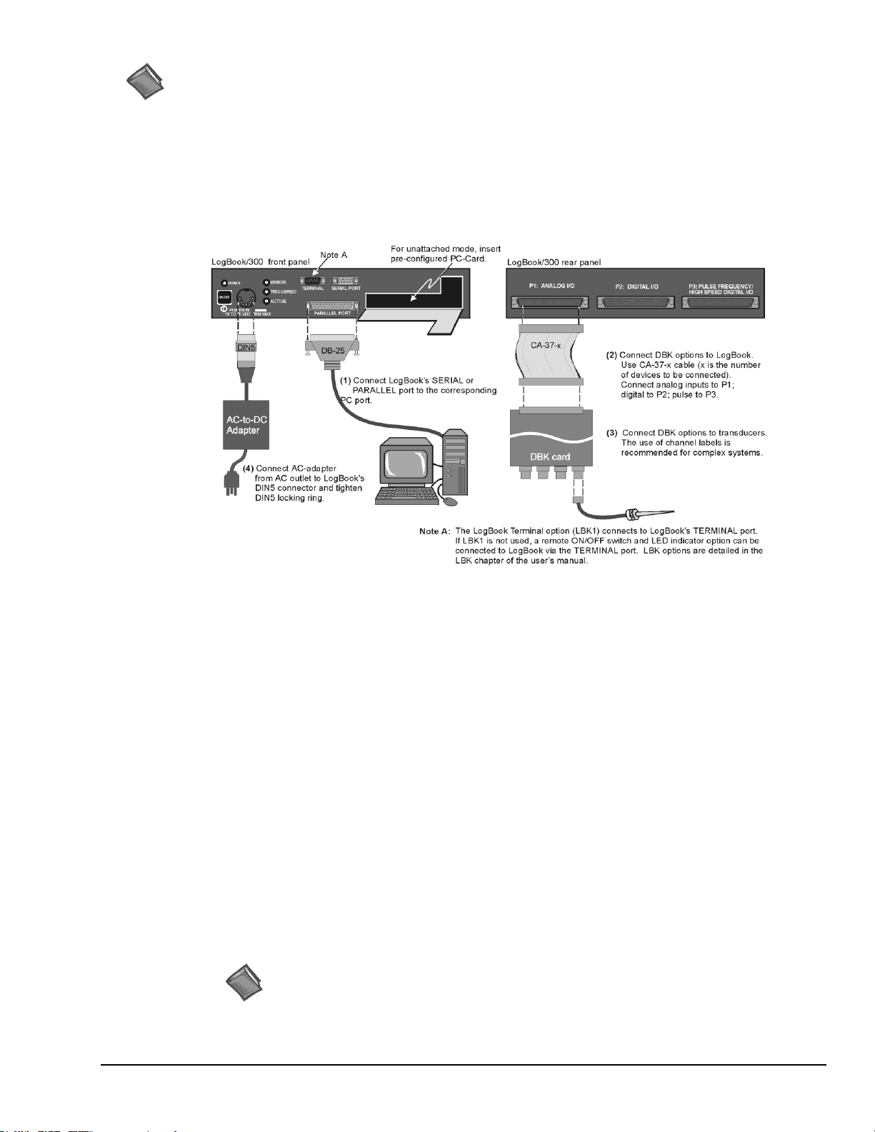
The following hardware-connection figure and procedure are generic; details vary with system complexity.
After verifying that all equipment power is off, hardware connection typically proceeds as follows.
Refer to the previous figure as needed.
1. Connect LogBook/300 to PC. There are four ways for LogBook/300 to communicate with the host
PC. These are: parallel port, serial port to serial port, serial port to USB, and manual transportation
of the PC-Card. Note that the parallel port method is represented in the previous figure.
a) Parallel port to parallel port – If using the parallel port, connect a DB25male to DB25female parallel cable
[e.g., CA-35-2 or CA-35-6 (2ft. or 6ft. respectively)] to PARALLEL PORT on LogBook/300, and to the
corresponding parallel port on the host PC. When this method is used, the PC must be set to the ECP
mode. See ECP Parallel Port, page QS300-6 for additional information.
b) Serial port to serial port – If using the serial port, use a null modem serial cable (CA-47) to connect the
DB9 SERIAL PORT on LogBook/300 to the corresponding DB9 serial port on the host PC.
c) Serial port to USB port - Requires an adapter kit. To connect the LogBook to a USB port you will need a
RS-232 to USB Interface Adapter Kit p/n CA-232-USB-KIT (available from Measurement Computing).
Refer to the associated Quick Start document (QS RS-232_to_USB_Interface.pdf) for a list of the kit’s
contents and for RS-232 to USB conversion instructions. The pdf is included on Data Acquisition CD
(rev 8.1.2 and hig
.
d) PC-
LogBook/300 Quick Start Guide QS300-3
Reference Note:
LogBook User’s Manual PDF.
Card
communication is accomplished via the PC-Card. To provide the PC-Card with the correct configuration
file, it must be configured from the PC, through LogView. After the PC-Card is configured, it is inserted
into LogBook’s PC-Card slot, located behind the front panel door.
Information pertaining to PC-Cards can be found in chapter 1 and in the LogView section of the
her)
–
With PC-Card communication, LogBook/300 does not require a connection to the computer, as
Page 29
Reference Note:
For DBK card related information, refer to the DBK Options Manual PDF. The document is
included on the Data Acquisition CD and is also available on our web-site.
CAUTION
For analog signal inputs via P1, do not exceed -35 VDC or +45 VDC.
Exceeding these limits could result in equipment damage.
Reference Note:
Refer to the device-specific sections of the LBK Options chapter of the user’s manual and to
the DBK Options Manual PDFs for information regarding these devices. Note that certain
DBK options require manual configuration.
2. Connect the LogBook/300 to the DBK cards and modules. Most of the analog DBKs connect to P1
on the rear panel; the digital DBKs generally connect to P2.
Note: The CA-37-x cable can daisy-chain several DBKs including the DBK41, which has a built-in
P1 bus connection for 10 DBK cards. The x in the cable part number refers to the number of
devices that can be connected to a device, for example: a CA-37-1 cable has two DB-37
connectors, one for connecting to the LogBook and another for connecting the card or
module. Pinouts for P1, P2, and P3 are included in the System Expansion chapter.
3. Connect DBK(s) to transducer(s). Follow instructions for the specific DBK(s) as described in the
DBK Option Cards & Modules User’s Manual, as well as instructions for the applicable transducers.
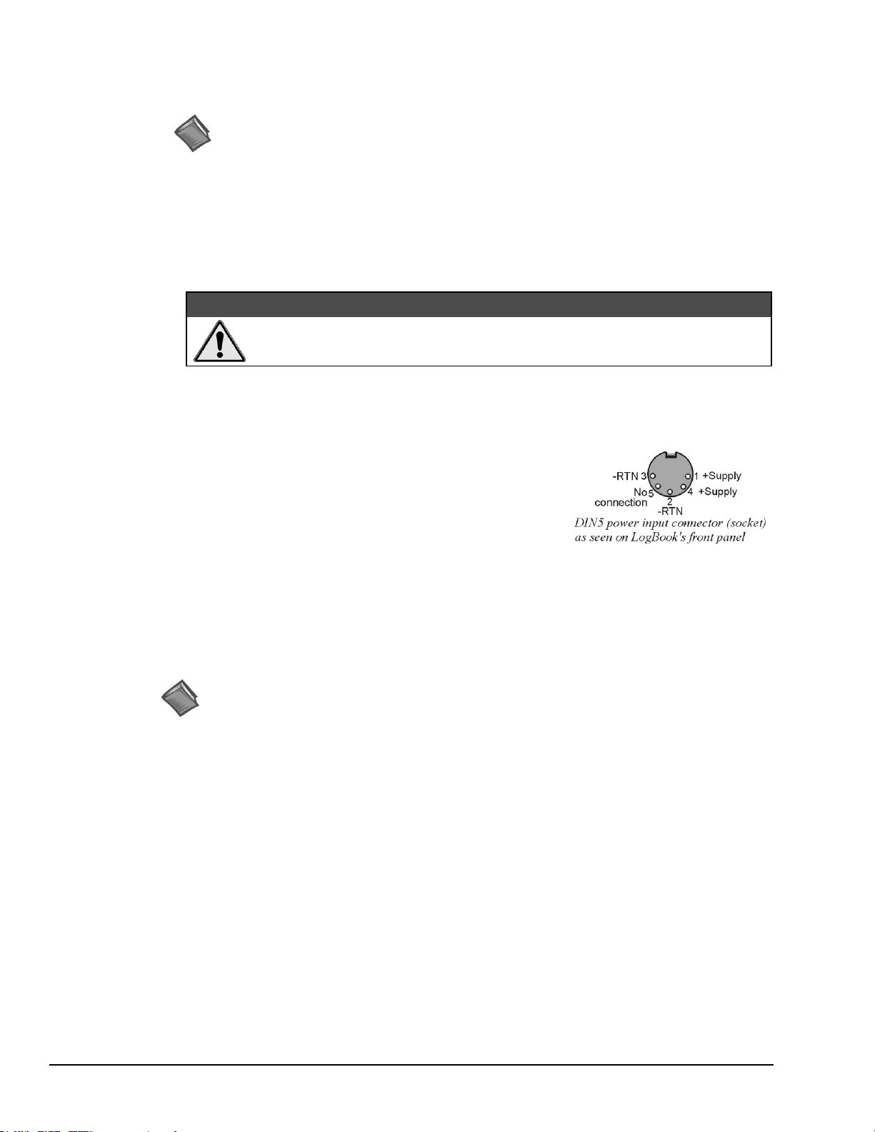
4. Connect the LogBook/300 to a suitable power source such as the
included AC-to-DC adapter or the optional DBK34A. DC
power sources such as a car batteries must supply 10 to 45 VDC
and use the correct DIN5 pinout (see figure). A locking DIN5
connector assures a secure power connection for applications
subject to vibration or thermal stress.
5. Optional - Just one cable connects between the LBK1
(via RJ-11 connector) and the LogBook/300 (via a DB9 connector). The standard cable is 6 feet
long. An optional 25 foot cable is available. See chapter 5 of the LogBook User’s Manual PDF for
details regarding the installation of LBK1.
Hardware Configuration
LogBook/300's top cover does not need to be removed, except to add or remove an LBK option, or to
replace the fuse.
Most LogBook/300 configuration is done via software as described in the LogBook/300 Device
Configuration section of this document (page QS300-5). LogBook/300 configuration does not require the
setting of jumpers or switches, unless the RS-485 communication option is being used.
QS300-4 LogBook/300 Quick Start Guide
Page 30
Upon completing the software installation, continue with LogBook/300 Device Configuration.
LogBook/300 Device Configuration
A configuration utility is supplied via a control panel applet. The LogBook Configuration applet allows
you to add a device, remove a device, or change existing configuration settings. From this same window,
you can also access a built-in utility to test the connected device for current setup and performance.
LogBook Configuration can be found in the Microsoft Windows Control Panel. The Control Panel can be
navigated to from Windows desktop Start button as follows:
Start Settings Control Panel
You can enter LogBook Configuration during driver installation or whenever you wish to add, remove or
change device configuration settings.
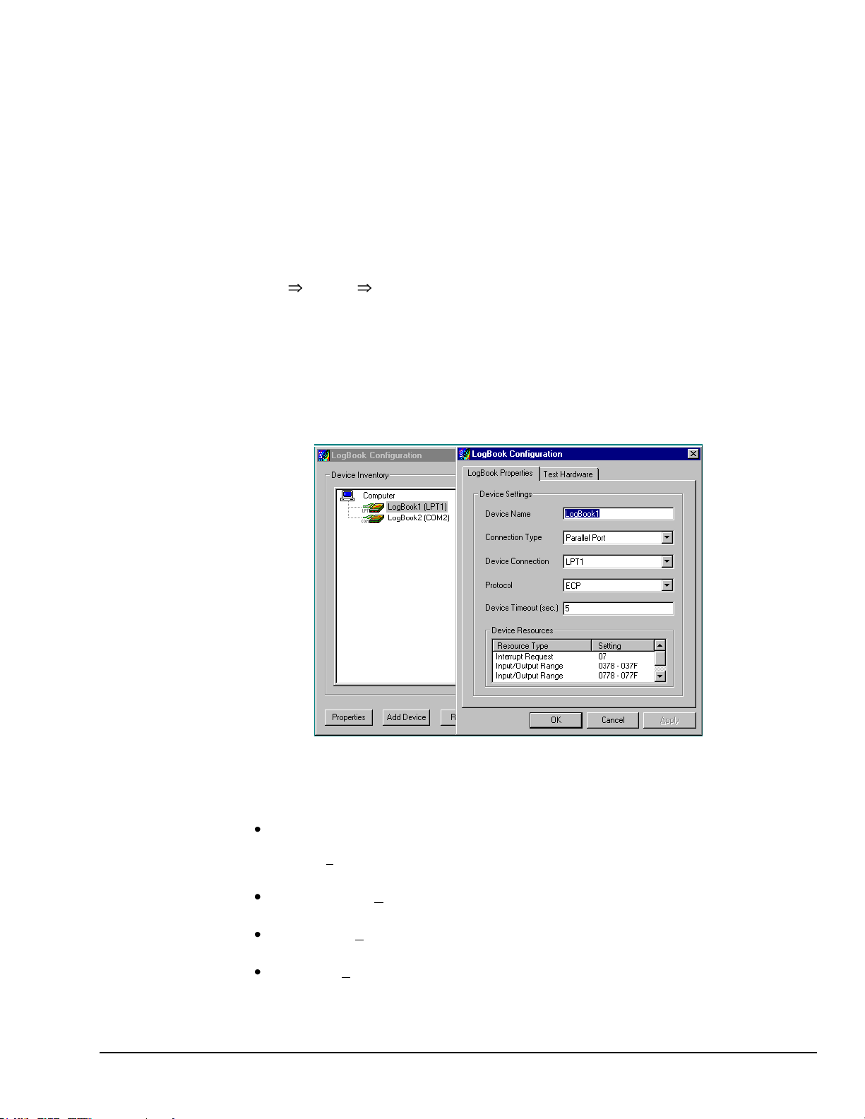
The first configuration window will display configured devices in the Device Inventory field based on the
port they’re connected to. Devices are represented by an icon and text, e.g., LogBook (LPT1), as can be
seen in the following figure. If no devices are configured, the device inventory field will remain blank.
The figure shows the first and second configuration windows overlapped.
LogBook Configuration Windows
The four buttons across the bottom of the first configuration window (previous figure) are used as follows:
Properties. Configuration settings for a device can be changed or modified from the corresponding
properties window. To do so, double-click the device icon or single-click the device and then singleclick the Properties button. The second configuration window will appear for the selected device as
shown in the previous figure.
Add Device. The Add Device button is used to add a device configuration whenever a new device is
added to the system. LogView cannot recognize a device unless listed in the configuration window.
Remove. The Remove button is used to remove a device from the configuration. A device may be
removed if it is no longer installed or if the device’s configuration no longer applies.
Close. The Close button may be used at any time to exit the LogBook Configuration applet.
The second configuration window displays the properties for the selected LogBook/300. Fields include:
LogBook/300 Quick Start Guide QS300-5
Page 31

Device Name is displayed with the default name, numbered successively as configured. This field can
To use parallel port communication with an attached LogBook/300, your PC must
support the ECP protocol AND be set in the ECP mode.
To ensure ECP compatibility after proper setup, use the Test Hardware utility
(described on page QS300-7). Before testing, make sure LogBook/300 is properly
connected, powered on, and that the Parallel Port Mode is set to ECP (in BIOS Setup).
CAUTION
Making errors in BIOS Setup can disrupt your system’s operation. If test hardware
indicates a problem and you have inadequate experience with the BIOS Setup utility,
consult your System Administrator or other qualified individual.
be changed to any descriptive name as desired.
Connection Type can be serial or parallel port.
Device Connection specifies the port name.
Protocol is used to set the parallel port protocol (ECP only) or serial protocol (RS-232 or RS-485).
Device Timeout specifies the number of seconds LogView will be wait for a LogBook response before
displaying an error condition.
ECP Parallel Port
The majority of today’s PCs support the Enhanced Computer Port protocol (ECP). If your computer does
not support ECP, you can communicate with the LogBook/300 via the RS-232 serial port, or you can add an
ECP-compatible ISA board or PC-Card parallel port. Setting the PC to ECP mode varies with different
computers. On some computers, you can enter the BIOS Setup utility from Windows Settings or during
startup by pressing the F1 function key. The Parallel Port Mode property can be found under the Peripheral
Configuration group menu item. If necessary, consult your PC’s documentation or your PC’s manufacturer.
QS300-6 LogBook/300 Quick Start Guide
Page 32

Serial Port
LogBook Properties Tab
Test Hardware Tab
Testing the LogBook/300 device might cause the system to hang. If test results are not
displayed within 30 seconds, or if the system does not respond properly do the following:
Reboot the system.
Upon power-up, re-enter the LogBook Configuration.
Ensure the configuration settings are correct. Change the settings as applicable.
If the selected device is connected to a serial port the properties window will include the fields shown in the
following figure. Baud rate can be set from 1200 to 115200 bits per second (default 9600). When all fields
have been changed to the desired settings, you can click on one of the following options:
Apply to store the device configuration. Parameters are not locked in until you click the Apply button.
If you make changes and don’t click Apply, clicking the Test button in Test Hardware will yield
unexpected errors.
OK to store the configuration and exit the current property screen.
Cancel to exit the current screen without storing any changes.
Test Hardware to test the current device.
Testing the Hardware
Before testing LogBook/300:
(a) Verify the device has been properly installed
(b) Make sure the communication cable (serial or parallel) is firmly in place to the proper ports.
(c) Verify the device is powered-on.
To begin the test, click the Test button. Test results should be displayed within a few seconds.
Test results indicate if the device is online (properly connected, powered on and ready to transfer the data)
or offline. If the device is online, Performance Test will display Download and Upload speed rates. These
rates represent the maximum speed at which downloading and uploading files can be performed. Actual
transfer time will depend on channel configuration and the size of the transfer.
LogBook/300 Quick Start Guide QS300-7
Page 33

Acquisition Configuration
Reference Note:
Configuring the acquisition is described in the LogView section of the LogBook User’s
Manual PDF, which is included on the Data Acquisition CD and on our web-site.
Reference Notes:
An example of 2-point calibration is provided under the Procedures heading in the
LogView section of the manual.
For information on calibrating the DBK16 and the DBK43A, refer to the
DBK Option Cards and Modules User’s Manual (p/n 457-0905).
An acquisition is configured using LogView on a PC and then stored as an acquisition setup file on a
PC-Card. The PC-Card may be in an attached LogBook/300 or in the PC to be later manually transferred to
an unattached LogBook/300. The system’s DBK cards are listed; the scan sequence is defined; the trigger
conditions are specified, etc.
A Note about Calibration
Calibration is typically performed automatically through LogView software; however, some DBKs may
require manual calibration. LogView’s 2-point calibration fine-tunes the reading’s slope and offset error
(mx+b). DBKs working with non-linear sensors typically condition/convert the reading to a linear form.
Otherwise, a non-linear analog input signal is difficult to read accurately. Careful use of the calculated
channels may yield usable approximations in simple, limited-range conditions.
QS300-8 LogBook/300 Quick Start Guide
Page 34

LogBook/360 Quick Start Guide
Software Installation …… QS360-1
Setting Up the Card Drawer …… QS360-3
Connecting the LogBook/360 to the PC,
External DBKs, and Power …… QS360-6
Hardware Configuration …… QS360-7
LogBook/360 Device Configuration… QS360-8
Testing the Hardware …… QS360-10
Acquisition Configuration …… QS360-10
A Note About Calibration …… QS360-11
Before you get started
verify that you have the following items.
LogBook/300
TR-40U Power Supply
Serial/Parallel Patch Cable, or PC Card Reader
PC with ECP (Enhanced Capabilities Port)
Data Acquisition CD
Monitor: SVGA, 1024 x 768 screen resolution
Windows 2000 SP4 and Windows XP users:
PC with Intel™ Pentium [or equivalent], 1 GHz;
Windows Vista users:
PC must be Windows Vista Premium Ready
LogBook/360 combines the features and capabilities of LogBook/300 with a DBK60 expansion chassis. The lower
portion of the front panel has three male DB37 connectors (P1, P2, and P3) for system expansion, and a post for
connecting to CHASSIS ground. The upper section is nearly identical to LogBook/300.
IMPORTANT! Software must be installed first!
512 MB memory; 10 GB disk space
Software Installation
1. Close all running applications on the host PC.
2. Remove previous version drivers, if present. You can do this through Microsoft’s Add/Remove Programs
feature.
3. Insert the Data Acquisition CD (8.1.2 or higher) into your CD-ROM drive and wait for the PC to auto-run. An
Opening Screen will appear. If AutoRun is disabled: (a) right click Windows Start menu, (b) select Explore; and
(c) double-click MasterSetup.exe. As an alternative to using the CD, you can download software from:
www.mccdaq.com/products/software.aspx.
4. Click the <ENTER SETUP> button.
Note: If you are downloading software from our website, follow instructions provided there.
5. From the hardware selection screen, select your data acquisition device then follow the on-screen instructions.
Note: To enable all LogView features:
(a) From LogView’s main window, open the File pull-down menu,
(b) select Authorization,
(c) enter ED7B55484273 in the dialog box and apply the code.
LogBook/360, Front Panel
LogBook/360 Quick Start Guide QS360-1
Page 35

Reference Notes:
Depending on the nature of your LogBook system, you may find one or more of the following references to the
LogBook User’s Manual PDF helpful. The PDF manual is included on the Data Acquisition CD and is also
available on our web-site.
o For block diagrams and operational overviews, refer to Chapter 1 of the LogBook User’s Manual PDF.
o For system expansion and calculating system power, refer to Ch. 4 and to the DBK Basics section.
o For information regarding LBK options, refer to Chapter 5.
o For specific DBK card information, refer to the DBK Options Manual PDF.
Note: The LogBook/360 rear panel supports three termination panels. Many different combinations are
possible.
WARNING
Electric shock hazard. Turn off power to all system-connected devices prior to connecting or
disconnecting cables, or setting hardware configurations. Failure to do so could result in electric shock
or death, and equipment damage, even under low-voltage conditions.
CAUTION
Use ESD tools, containers, and procedures during setup of DBK cards. Electrostatic
discharge can damage some components. To prevent pin damage, align DBK cards with the
backplane DB37 connectors, then gently press them together.
When using LogBook in attached mode, the PC-Card [in LogBook] must already have the file
logbook.sys. Otherwise, LogView cannot communicate with LogBook, and LogBook will
appear dead.
QS360-2 LogBook/360 Quick Start Guide
Page 36

Setting Up the Card Drawer
Leave jumpers JP1 and JP2 in place unless a DBK33 is being used. If a DBK33 is being
used configure the P1 interconnect board according to the table presented in step 6.
LogBook/360 can house three DBK cards internally, and make use of various termination panels. For user convenience, a card
drawer can be slid free of the device. The following steps should be used when adding, removing, or changing cards. Refer to
the following figure as needed.
1 – Turn off system power and disconnect LogBook/360.
Turn power off to the LogBook/360 and all connected devices. Disconnect LogBook/360 from the system.
2 – Remove top cover.
If you need to make any change on the LogBook motherboard, you will need to remove the top cover. Otherwise, the cover
can remain in place. To remove the top cover, simply remove the two top cover screws and slide the cover free of the
device.
3 – Remove card drawer.
A. Remove the two screws that hold the card drawer to the chassis.
B. Loosen the three termination panel thumbscrews.
C. Carefully pull the card drawer free of the chassis.
4 – Remove termination panels.
For each termination panel, remove the two screws that mount it to the card drawer, then remove the termination panel.
5 – Determine power requirements.
Depending on the power needs of your system’s DBK cards, you may need to add a power card.
Refer to the DBK Basics section of the LogBook User’s Manual PDF in regard to calculating your
system’s power requirement.
If the required power is more than the available power your system will require auxiliary power. One of two power
supply cards can be used with LogBook/360:
DBK32A – This DBK supplies ±15 V for use with a LogBook, DaqBook, or DaqBoard.
DBK33 – This DBK supplies +5 V and ±15 Vfor use with Log Book, DaqBook, DaqBoard,
or Daq PC-Card.
LogBook/360 Quick Start Guide QS360-3
Page 37

6 - FOR DBK33 USERS ONLY! Configure the P1 interconnect board for power source.
This step only applies when a DBK33 is being used with the system.
If you are not using a DBK33 skip to step 7.
The schematic to the right shows the LogBook/360 jumpers, JP1 and
JP2, which are used to distribute the LogBook’s +5V power supply.
DBK cards that attach to the LogBook’s P1 bus need +5V, +15V, and
-15V power sources to operate. Typically, the LogBook’s power supply
meets this requirement, but if additional power is needed, a DBK32A or
DBK33 must be added.
The LogBook’s power supply employs diode protection on its +/-15V
supplies so that no conflict will take place when a DBK32A or DBK33 is
added to the P1 bus. However, adding a DBK33, with its +5V source,
necessitates the proper positioning of the JP1 and JP2 jumpers.
Adding a DBK33 to your system with the jumpers set incorrectly can
damage your LogBook, DBK33, and other system components. Refer to
the following table for important information regarding configuration.
CAUTION
Adding a DBK33, with its +5V source, necessitates the proper positioning of the JP1 and JP2
jumpers on the LogBook/360 P1 interconnect board. Adding a DBK33 to your system with the
jumpers set incorrectly can damage the LogBook, DBK33, and other system components.
WHEN JP1 AND JP2 JUMPERS ARE IN PLACE A DBK33 CANNOT BE USED IN THE
SYSTEM!
P1 Interconnect Board Configurations for DBK33 Applications
JP1
JP2
P1 Interconnect
Board*
LogBook +5V Power Source
Notes Pertaining to DBK33
Internal P1
Bus
External P1
Bus
In
Out Yes
No
When the JP1 jumper is in place and the JP2
jumper is out, if the system is using external
DBKs the DBK33 will need to be external.
Internal DBKs will be powered from
LogBook’s internal P1 bus.
Out
In No
No
When the JP1 jumper is out and the JP2
jumper is in place, if DBKs are used
internally or externally, the DBK33 can be
internal or external and will power both
internal and external DBK cards.
Out
Out No
No
When the JP1 and JP2 jumpers are both out,
the following apply:
o If using internal DBKs, you will need to
use an internal DBK33.
o If using external DBKs, you will need to
use an external DBK33.
Leave jumpers JP1 and JP2 in place, unless a DBK33 is being used. If a DBK33 is being
used configure the P1 interconnect board according to the above table.
* Refer to the LogBook/360 Hardware Setup figure on page QS360-3 for the P1 interconnect board’s location.
QS360-4 LogBook/360 Quick Start Guide
Page 38

7 – Install power card if necessary.
If you determined in step 5 that additional power was needed, add a DBK32A or DBK33 power card to the
chassis. The DBK Option Cards & Modules User’s Manual includes detailed information regarding these
power-related cards.
A. Carefully align the power card’s DB37 connector with a DB37 connector on the interconnect board and
gently press them together.
B. Mount the power card with two screws into the standoffs on the card drawer.
8 – Configure DBK cards.
Configure unique channel addresses with the jumpers on the DBK cards. Some cards have other jumpers and/or
DIP switches. Refer to the specific DBK sections of the DBK Options Manual (p/n 457-0905) as needed.
9 – Install DBK cards.
You must use all analog DBK cards in the LogBook/360; unless you have a factory modification that allows the
use of all digital cards. You can not use both analog and digital cards at the same time.
A. Carefully align the DBK card’s DB37 connector with a DB37 connector on the interconnect board and
gently press them together (see figure).
B. Mount the DBK card with two screws into the standoffs on the card drawer (see previous figure).
C. Continue installation of any remaining DBK cards.
10 – Connect internal signals.
Connect signal inputs from DBK cards to termination panels. DBK cards connect to the termination panels in
various ways (see figure and particular DBK sections in the DBK Option Cards and Modules User’s Manual):
Single-ended connections use analog common.
Differential connections require the proper polarity, typically red-to-red for high (+)
and black-to-black for low (-).
For thermocouples, red is generally the low side. Always make sure the T/C connector and wire type
match the T/C type used.
11 – Install termination panels.
Mount the termination panels to the card drawer with two screws for each panel.
12 – Install card drawer.
The card drawer slides into the bottom track of the chassis.
A. Hold the card drawer by its handle and tilt it up slightly. Place it on the bottom track of the chassis.
B. Carefully slide the card drawer into the chassis. When it engages the bottom track, level the card drawer and
continue inserting it until it engages with the P1 interconnect board.
C. Tighten the three captive thumbscrews holding the termination panels to the chassis.
D. Install the two screws holding the card drawer to the chassis.
13 – Connect external signals.
Connect signal inputs from sensors to termination panels.
14 – Install top cover.
If the top cover was removed, slide it back into place and secure with two screws.
LogBook/360 Quick Start Guide QS360-5
Page 39

LogBook/360 System, “Attached Mode,” Basic Connections
Note: Rear panel connections may be made via terminal blocks, as discussed in the previous section,
Card Drawer Setup.
Step 4
Connect the LogBook’s DIN5 power in connector to the AC adapter
and connect the adapter to a suitable power outlet. Note that other
power options are discussed in the DBK Basics section of this
manual.
Connecting the LogBook/360 to the PC, External DBKs, and to Power
The following hardware-connection figure and procedure are generic; details vary with system complexity. For
“unattached mode,” a pre-configured PC-Card is inserted in the PC-Card slot, and no connection to a PC is made.
The following figure illustrates the “attached” mode.
Note: Connecting LogBook/360 to a PC applies to the “attached mode” only. Many applications will make use of
three internal DBK cards only, having no need to attach external DBK cards or modules as discussed in the
following text.
After verifying that all equipment power is off, hardware connection typically proceeds as follows.
Refer to the above figure as needed.
1. Connect the LogBook/360 to the host PC. There are four ways for LogBook/360 to communicate
with the PC. These are: parallel port, serial port to serial port, serial port to USB, and manual
transportation of the PC-Card. Note that the parallel port method is represented in the previous
figure.
a) Parallel port to parallel port – If using the parallel port, connect a DB25male to DB25female parallel
cable [e.g., CA-35-2 or CA-35-6 (2ft. or 6ft. respectively)] to PARALLEL PORT on LogBook/360, and to
the corresponding parallel port on the host PC. When this method is used, the PC must be set to the ECP
mode. See ECP Parallel Port, page QS360-9 for additional information.
b) Serial port to serial port – If using the serial port, use a null modem serial cable (CA-47) to connect the
DB9 SERIAL PORT on LogBook/360 to the corresponding DB9 serial port on the host PC.
QS360-6 LogBook/360 Quick Start Guide
Page 40

c) Serial port to USB port - Requires an adapter kit. To connect the LogBook to a USB port you will need a
Reference Note:
Information pertaining to PC-Cards can be found in chapter 1 and in the LogView section of the
LogBook User’s Manual PDF.
CAUTION
For analog signal inputs via P1, do not exceed -35 VDC or +45 VDC.
Exceeding these limits could result in equipment damage.
4. Connect LogBook/360 to a suitable power source, such as
the included AC-to-DC adapter or optional DBK34A
UPS / Battery Module. DC power sources such as a car
batteries must supply 10 to 45 VDC and use the correct
DIN5 pinout (see figure). A locking DIN5 connector
assures a secure power connection for applications subject
to vibration and thermal stress.
DIN5 Power Input Connector
(As seen on LogBook/360 Front Panel)
Reference Notes:
Refer to the device-specific sections of the LBK options chapter [in the user’s manual PDF]
and the DBK Option Cards & Modules User’s Manual PDF for information regarding these
devices. Note that certain DBK options require manual configuration.
RS-232 to USB Interface Adapter Kit p/n CA-232-USB-KIT (available from Measurement Computing).
Refer to the associated Quick Start document (QS RS-232_to_USB_Interface.pdf) for a list of the kit’s contents
and for RS-2
higher).
d) PC-Card – With PC-Card communication, LogBook/360 does not require a connection to the computer, as
communication is accomplished via the PC-Card. To provide the PC-Card with the correct configuration
file, it must be configured from the PC, through LogView. After the PC-Card is configured, it is inserted
into LogBook’s PC-Card slot, located behind the front panel door.
32 to USB conversion instructions. The pdf is included on Data Acquisition CD (rev 8.1.2 and
2. Connect LogBook/360 to the DBK cards and modules. For connecting internal DBK cards, refer to
the earlier section entitled, Setting Up the Card Drawer.
Most analog DBKs connect to P1; digital DBKs generally connect to P2. Refer to the DBK Options
Manual (457-0905) in regard to your particular DBKs and for general DBK installation details.
The CA-37-x cable can daisy-chain several DBKs including the DBK41, which has a built-in
P1 bus connection for 10 DBK cards. The x in the cable part number refers to the number of devices
that can be connected (a CA-37-1 actually has two DB-37 connectors).
Note: Chapter 4 of the LogBook User’s Manual PDF includes pinouts for LogBook/360’s P1, P2,
and P3 connectors.
3. Connect DBK(s) to transducer(s). Follow instructions for particular DBK as described in the
DBK Option Cards & Modules User’s Manual and for the particular transducer. Some DBKs can
accommodate both BNC and screw-terminal connections.
Hardware Configuration
LogBook/360's top cover does not need to be removed, except to add or remove an LBK option, or to
replace the fuse.
Most LogBook/360 configuration is done via software as described in section, LogBook/360 Device
LogBook/360 Quick Start Guide QS360-7
Configuration. LogBook/360 configuration does not require the setting of jumpers or switches, unless
the RS-485 communication option is being used.
Page 41

LogBook/360 Device Configuration
A configuration utility is supplied via a control panel applet. The LogBook Configuration applet allows
you to add a device, remove a device, or change existing configuration settings. From this same window,
you can also access a built-in utility to test the connected device for current setup and performance.
LogBook Configuration can be found in the Windows Control Panel. The Control Panel can be navigated
to from Window’s desktop Start button as follows:
Start Settings Control Panel
You can enter LogBook Configuration during driver installation or whenever you wish to add, remove or
change device configuration settings. The following description applies to either method.
The first configuration window will display configured devices in the Device Inventory field based on the
port they’re connected to. Devices are represented by an icon, and text, e.g., LogBook (LPT1), as can be
seen in the following figure. If no devices are configured, the device inventory field will remain blank. The
figure shows the first and second configuration windows overlapped.
LogBook Configuration Windows
The four buttons across the bottom of the first configuration window (previous figure) are used as follows:
Properties. Configuration settings for a device can be changed or modified from the corresponding properties
window. To do so, double-click the device icon or single-click the device and then single-click the Properties
button. The second configuration window will appear for the selected device as shown in the previous figure.
Add Device. The Add Device button is used to add a device configuration whenever a new device is added to
the system. LogView cannot recognize a device unless listed in the configuration window.
Remove. The Remove button is used to remove a device from the configuration. A device may be removed if it
is no longer installed or if the device’s configuration no longer applies.
Close. The Close button may be used at any time to exit the LogBook Configuration applet.
The second configuration window displays the properties for the selected LogBook. Fields include:
Device Name is displayed with the default name, numbered successively as configured. This field can be
changed to any descriptive name as desired.
Connection Type can be serial or parallel port.
Device Connection specifies the port name.
Protocol is used to set the parallel port protocol (ECP only) or serial protocol (RS-232 or RS-485).
Device Timeout specifies the number of seconds LogView will be wait for a LogBook response before
displaying an error condition.
QS360-8 LogBook/360 Quick Start Guide
Page 42

To use parallel port communication with an attached LogBook/360, your PC must
support the ECP protocol AND be set in the ECP mode.
To ensure ECP compatibility after proper setup, use the Test Hardware utility
(described on page QS360-10). Before testing, make sure LogBook/360 is properly
connected, powered on, and that the Parallel Port Mode is set to ECP (in BIOS Setup).
CAUTION
Making errors in BIOS Setup can disrupt your system’s operation. If test hardware
indicates a problem and you have inadequate experience with the BIOS Setup utility,
consult your System Administrator or other qualified individual.
LogBook Properties Tab
Test Hardware Tab
ECP Parallel Port
PCs made since 1994 probably support the Enhanced Computer Port protocol (ECP). If your parallel port
does not support ECP, you can communicate with the LogBook/360 via the RS-232 serial port, or you can
add an ECP-compatible ISA board or PC-Card parallel port. Setting the PC to ECP mode varies with
different computers. On some computers, you can enter the BIOS Setup utility from Windows Settings or
during startup by pressing the F1 function key. The Parallel Port Mode property can be found under the
Peripheral Configuration group menu item. If necessary, consult your PC’s documentation or your PC’s
manufacturer.
Serial Port
If the selected device is connected to a serial port the properties window will include the fields shown in the
figure at right. Baud rate can be set from 1200 to 115200 bits per second (default 9600). When all fields
have been changed to the desired settings, you can click on one of the following options:
Apply to store the device configuration. Parameters are not locked in until you click the Apply
button. If you make changes and don’t click Apply, clicking the Test button in Test Hardware will
yield unexpected errors.
OK to store the configuration and exit the current property screen.
Cancel to exit the current screen without storing any changes.
Test Hardware to test the current device.
LogBook/360 Quick Start Guide QS360-9
Page 43

Testing the Hardware
Testing the LogBook/360 device might cause the system to hang. If test results are not
displayed within 30 seconds, or if the system does not respond properly do the following:
Reboot the system.
Upon power-up, re-enter the LogBook Configuration.
Ensure the configuration settings are correct. Change the settings as applicable.
Reference Note:
Configuring the acquisition is described in the LogView section of the user’s manual PDF.
Before testing LogBook/360:
a) Verify the device has been properly installed.
b) Make sure the communication cable (serial or parallel) is firmly in place to the proper ports.
c) Verify the device is powered-on.
To begin the test, click the Test button. Test results should be displayed within a few seconds.
Test results indicate if the device is online (properly connected, powered on and ready to transfer the data)
or offline. If the device is online, Performance Test will display Download and Upload speed rates. These
rates represent the maximum speed at which downloading and uploading files can be performed. Actual
transfer time will depend on channel configuration and the size of the transfer.
Acquisition Configuration
An acquisition is configured using LogView on a PC and then stored as an acquisition setup file on a
PC-Card. The PC-Card may be in an attached LogBook/360 or in the PC to be later manually transferred to
an unattached LogBook/360. The system’s DBK cards are listed; the scan sequence is defined; the trigger
conditions are specified, etc.
QS360-10 LogBook/360 Quick Start Guide
Page 44

A Note about Calibration
Reference Notes:
An example of 2-point calibration is provided under the Procedures heading in the
LogView section of the user’s manual PDF.
For information on calibrating the DBK16 and the DBK43A, refer to the
DBK Option Cards and Modules User’s Manual PDF.
Calibration is typically performed automatically through LogView software; however, some DBKs may
require manual calibration. LogView’s 2-point calibration fine-tunes the reading’s slope and offset error
(mx+b). DBKs working with non-linear sensors typically condition/convert the reading to a linear form.
Otherwise, a non-linear analog input signal is difficult to read accurately. Careful use of the calculated
channels may yield usable approximations in simple, limited-range conditions.
LogBook/360 Quick Start Guide QS360-11
Page 45

System Expansion 4
Expansion and Enhancement Options….. 4-1
What are LBK Options?……4-1
What are DBK Options?……4-2
Power Options …… 4-3
Other Options ……4-3
Considerations……4-4
DBK Configuration …… 4--4
Dimensional and Environmental Factors……4-4
Mechanical Setup Options……4-5
P1, P2, and P3 Port Connectors……4-6
Reference Notes:
• Power Supplies, Power Connectors, and Calculating Power Needs are topics that are discussed in the
DBK Basics section, which immediately follows this chapter.
• The chapter entitled, LBK and other non-DBK Options, discusses several non-DBK related options that
can be used with LogBook. These include COM/422/485, memory expansion, LBK1 remote terminal,
LBK2 Digital-to-Analog Output, and remote On/Off switch/LED indicator options.
• The DBK Option Cards & Modules User’s Manual (p/n 457-0905), details optional DBK cards and
modules and addresses DBK power issues. As a part of product support, the manual is automatically
loaded onto your hard drive during software installation. The default location is the Programs group,
which can be accessed throught the Windows desktop.
Expansion and Enhancement Options
A variety of cards and modules can be used to expand and enhance LogBook systems. These options are
found in three categories, LBK options, DBK options, and other. In addition to being discussed briefly
below, LBK options are detailed in the following chapter, and DBK options are detailed in the
DBK Option Cards & Modules User’s Manual (p/n 457-0901). The “other” options are detailed in this
chapter.
What are LBK Options?
LBK options are LogBook add-on features that can be used to enhance your system. The LBK options
described briefly below, and are detailed in the following chapter.
LBK/COM/422/485, RS-232 Board with an RS-422/485 Option. The standard LogBook
communications board supports RS-232 only. However, the LogBook can be purchased with the
additional capability for RS-422 and RS-485. These optional boards (p/n LBK/COM/422/485) have
circuitry for all three communication protocols.
LBKMEM1 or LBKMEM1U, 16 MB DRAM Memory Expansion. The standard 4-MB RAM can be
user-replaced with a 16 MB board (LBK/MEM1-U). The expanded memory creates a larger data buffer,
allowing more time to swap PC-Cards. This is convenient when using fast scan rates. Note that the 16 MB
memory option can also be installed at the factory (LBK/MEM1).
LBK1, Remote Terminal with LCD Screen. LBK1 provides a keypad to control the system’s basic
operation when no PC is attached and a LCD screen for viewing system status. A special rack (p/n
Mount1) is available to attach the LBK1 to the top of LogBook. For applications in harsh environments, a
special enclosure can be used to shield the unit from water and thermal stress.
LogBook User’s Manual 957096 System Expansion 4-1
Page 46

LBK2, 4-channel Digital-to-Analog Output card. The LBK2 Digital-to-Analog output board contains
four 16-bit, voltage-output, digital-to-analog converters with a maximum update rate of 100 kHz per
channel. The board is intended for waveform generation, UUT (Unit Under Test) stimulus, and signal
feedback. Each converter has a fixed, full-scale output of ±10 VDC. The board’s operation must be
programmed through LogView.
What are DBK Options?
DBK option cards and modules exist for signal-conditioning, analog output, system I/O, auxiliary power,
and expansion. Various sensor types are accommodated, including high-voltage/current, strain gages,
thermocouples, isolation, relays, accelerometers, filtering, and simultaneous sample and hold.
Reference Notes:
No matter what the signal input from the transducer, DBKs produce output signals suitable for analog-todigital conversion (ADC). The output signals can be bipolar (typically -5 to +5 V) or unipolar (typically
0 to 10 V). The user can select a range of relevant values to correspond to the lowest and highest signal—
this range selection guarantees the highest resolution in 16-bit conversion by the ADC.
• For a general introduction to DBKs, refer to the DBK Basics section of this
manual. The text discusses the various categories of DBKs, connectivity issues,
tips on setting up a data acquisition system, and power considerations.
• DBK options are detailed in DBK Option Cards & Modules User’s Manual
(p/n 457-0905). As a part of product support, the manual is automatically loaded
onto your hard drive during software installation. The default location is the
Programs group, which can be accessed throught the Windows desktop.
Note: DBKs vary in their outputs and gain settings. Refer to the specifications for the particular DBK
used.
Basic Connection Concepts
Most system expansions stem from the 37-pin Signal I/O ports P1, P2, and P3. Note that LogBook/360
combines the features and capabilities of LogBook/300 with those of a DBK60 expansion chassis. In
addition, LogBook/360 has a pre-installed serial communications card that provides GPS and AUX serial
ports as detailed in the chapter entitled, LBK and other non-DBK Options.
• P1. Each of 16 main (base) channels can support up to 16 sub-channels and thereby provide
expansion up to 256 analog input channels. LogBook’s channel sequencer scans expansion channels
at the same high speed as the base channels. DBKs can be daisy-chained off the P1 connector of
LogBook or an expansion module. Some DBKs add another level of multiplexing and
programmable gain to each channel, and setting channel parameters properly sometimes requires
both hardware and software setup.
• P2. The Digital I/O port can accommodate the DBK20/21 (digital I/O cards), DBK23/24 (isolated
digital input/output chassis), DBK25 (8-channel relay card), and other compatible devices; up to
208 digital I/O lines.
• P3. The Pulse Frequency port can be used for analog output and other uses. A DBK11A provides
for easy signal connection via screw terminals or optional BNC connectors.
The following figure illustrates various expansion possibilities. Note that additional options exist.
DBK options are detailed in the DBK Option Cards and Modules User’s Manual (p/n 457-0905).
4-2 System Expansion 957096 LogBook User’s Manual
Page 47

A Few Possible Expansion Configurations
Note 1: LogBook/360 (not shown) combines the features and capabilities of LogBook/300 with those of a DBK60.
In addition, LogBook/360 has two additional serial ports.
Power Options
Power options are covered in the DBK Basics section, which immediately follows this chapter.
Other Options
LogBook/GPS, Global Positioning System & Serial Device Data Collection Support, LogBook/360
Only. This software-enabled option provides a means to collect serial data from various devices, convert it
to channel values, and store it synchronously with the devices analog and digital inputs. Virtually any
serial device that sources continuous ASCII data, including Global Positioning System (GPS) devices, gas
flow meters, and scales, is compatible. GPS devices conforming to the NMEA 0183 standard are
supported directly in the LogView interface, so no knowledge of the data format is necessary.
Note: The LogBook/GPS option is enabled from the Authorization dialog box, selected from LogView’s
File pull-down menu. Details are provided in chapter 6. Use the code shown below:
USE THIS CODE TO ENABLE COMPLETE LOGVIEW FUNCTIONALITY:
LogBook/Modem, Modem and Upload Scheduler Software Support. With this software-enabled
option, a modem-connected PC can communicate with LogBook virtually anywhere in the world. Any
Hayes-compatible modem can be attached to the LogBook’s serial port. Both standard desktop and
wireless modems are supported. The Upload Scheduler is an independent application that allows the user
to configure upload events on one or more LogBooks. To avoid waiting for a lengthy upload to complete,
the Scheduler can be configured to perform the upload during unattended off-hours. For example, three
upload events could be configured in the Scheduler, each for an upload of data at different hours. The
Upload Scheduler can save valuable time by performing unattended uploads; especially in cases where
modem-connected LogBooks are operating at slow baud rates.
Note: The LogBook/Modem option is enabled from the Authorization dialog box, selected from
LogView’s File pull-down menu. Details are provided in chapter 7. Use the above code.
LogBook User’s Manual 957096 System Expansion 4-3
ED7B55484273
Page 48

Remote On/Off Switch and LED Indicator Options. If LogBook’s female DB9 TERMINAL connector
is not being used for the LBK1 remote terminal or another device, it can be used to connect a remote on/off
switch and/or indicator LED. The following chapter provides the information needed to add any one of the
following three remote options:
• Remote On/Off Switch and LED
• Remote On/Off Switch (no LED)
• Remote LED Indicator (no remote switch)
Considerations
DBK Configuration
The DBKs are usually configured before the connections are made and power is applied. This order of
installation can prevent equipment damage and help ensure proper operation on startup.
Many DBKs have on-board jumpers and/or DIP switches used for setting channels and other variables.
These settings are discussed in the individual DBK sections of the DBK Option Cards and Modules User’s
Manual (p/n 457-0905), which is installed on the PC’s hard drive as a part of product support. The default
location is the Programs directory, accessible via the Windows Desktop.
For systems with many modules, stacking units together helps conserve space and assure easy cable runs.
Such stacking is typically accomplished with the use of a splice kit. The kit is shipped as part of the
package for several DBK modules. The splice plate kits include metal plates (fastener panels) that screw
onto the sides of a module. A vertical rack of several modules can be assembled. An optional handle is
available for portable use, for example, when using two stacked modules.
Prior to expanding your LogBook system you should review the following DBK Basics section of the
manual, with special attention to the section entitled, Tips on Setting up a Data Acquisition System. Prior
planning will go a long way towards optimizing your acquisition setup and will most likely save you time.
Dimensional and Environmental Factors
Before setting up your LogBook-based acquisition system, you should consider the following size and
environmental related factors.
LogBook/300 Dimensions: 8½ × 11 × 1-3/4 in. (216 × 279 × 44 mm). This enclosure has the same
footprint as the DBK modules for easy stacking of units.
LogBook/360 Dimensions: 14 × 11 × 3-7/16 in. (330 × 279 × 84 mm). The width (11”) provides for
convenient stacking of DBK modules.
Operating temperature/humidity: -40° to 140°F (-40° to 60°C) @ 0 to 95% RH, non-condensing.
Operation of the unit in environments exceeding these limits requires that a temperature-regulated
enclosure).
Storage temperature: -40° to 176°F (-40° to 80°C). The standard case is rugged but not designed for
immersion. Special enclosures are available for harsh environments.
All connectors, including the power connector, are locking. The D-sub connectors have thumbscrews and
the DIN5 power connector has a twist-lock ring to ensure solid connections are maintained.
4-4 System Expansion 957096 LogBook User’s Manual
Page 49

Mechanical Setup Options
DBK modules for packaging DBK expansion cards are available with three slots (DBK10, DBK60) or
10 slots (DBK41). The best option depends on the number of DBK cards in your system. For three or
fewer cards, you can use the stackable 3-slot DBK10, or 3-slot DBK60.
Note: DBK60 has several termination-panel options, e.g., BNC, Safety-jack, T/C, removable block
screw-terminal, slotted, and DB37-style.
For more than six cards, use the 10-slot DBK41. Several DBK41s can be daisy-chained to handle a large
number of DBKs in a system. Another packaging option is the use of special enclosures for harsh
environments. These enclosures can be locked to prevent tampering, conditioned for heat and/or cold, and
sealed air- or water-tight. For systems with many modules, stacking units together helps conserve space
and assure easy cable runs. Such stacking can be accomplished with adhesive dual-lock tabs or by the use
of fastener-panels (splice plates). The splice-plate method provides for a more rigid stacking, and is the
preferred method. Dual-lock tabs are convenient for mounting a Notebook PC to a LogBook or DBK
module.
Dual-lock tabs. Adhesive dual-lock tabs are typically
•
used to attach a notebook PC to a LogBook or to a DBK
module.
• Fastener panels. Optional splice plate kits can be used to
provide rigid stacking. These kits include metal plates that
form a vertical rack of two or more modules. This method
allows the “enclosure” to size itself as needed. A handle
can be attached for convenience.
LogBook User’s Manual 957096 System Expansion 4-5
Page 50

P1, P2, and P3 Port Connectors
LogBooks have three port connectors: P1, P2, and P3. For LogBook/300, these connectors are located on
the rear panel. For LogBook/360, they are on the front panel as discussed in the following note.
Connector pinouts begin on the next page.
Note: LogBook/360 actually has two sets of P1, P2, and P3 connectors, one internal set located on the
motherboard, and one external set located on the unit’s front panel. LogBook/360’s front panel P1,
P2, and P3 connectors connect to the motherboard’s P1, P2, and P3 via ribbon cables.
P1 (Analog Input)
LogBook’s P1 connector is compatible with all DBK options. Features and capabilities of P1 signals
include:
• High-performance signal connection for: ±10 V and 0-20 V input ranges, gains from ×1 to ×64 (each
gain and range calibrated individually), and an input stage with low crosstalk, high dynamic
impedance, small signal injection.
• All calibration is performed digitally; there are no pots to adjust.
• The sequencer depth (the number of channel readings in a scan) is 1024 analog channels and 128
digital channels.
• P1 includes an enhanced DBK-50 protocol that allows DBK cards or modules to identify themselves
and carry their own calibration data. These same connections provide for complete configuration of
DBK cards with that capability, while not requiring the use of jumpers.
CAUTION
For analog signal inputs via P1, do not exceed -35 VDC or +45 VDC or
equipment damage may result.
P2 (Digital I/O)
P2 is used with various kinds of digital I/O. For autonomous operation without an attached PC, the P2
outputs may be preset before the acquisition. The P2 digital outputs may be used as alarm outputs to
identify the detection of specified levels in the acquired data.
P3 (Pulse Frequency, High-Speed Digital I/O)
Features and capabilities of P3 signals include:
• Four 16-bit pulse counter channels that can be scanned along with analog inputs
• Additional digital I/O control lines for high-speed digital input and output.
• Four optional, internal, 16-bit ±10 V analog output channels (LBK2), useable for waveform or
control output, or additional control lines for external analog output expansion.
The 16 high-speed digital I/O lines, along with the additional digital I/O control lines can now be used for
real-time digital peripherals such as expanded digital input, or current or voltage DACs.
Optional, internal four-channel 16-bit waveform/control ±10 V DACs on P3:
• Initially setup to a static, preprogrammed voltage at the beginning of the acquisition.
• In the future, may be used for waveform or control outputs.
P1, P2, and P3 Pinout Tables
You can connect signals to LogBook’s P1, P2, and P3 port connectors using a CA-37-x cable
(via a D-shell 37-pin female connector), or a DBK11 screw-terminal card with component sockets.
This page and the next two contain P1, P2, and P3 pinouts.
4-6 System Expansion 957096 LogBook User’s Manual
Page 51

P1 – Analog I/O
Pin Signal Name Description for P1 Pin Use
1 +5 PWR +5 V supply @ 0.100 A
2 -15 VDC with diode -15 V supply @ 0.150 A
3 CHS 3 Channel select line for expansion cards
4 CHS 1 Channel select line for expansion cards
5 GS 1 Gain select line for expansion cards
6 GS 0 Gain select line for expansion cards
7 POWER GND Digital ground
8 NEGREF (-5 V) -5.0000 VDC @ 0.005 A reference used for various DBKs
9 POSREF (+5 V) +5.0000 VDC @ 0.005 A reference used for calibration with optional 4-channel D/A board
10 N/C No Connection
11 CH 7 LO IN/CH 15 HI IN Ch 7 LO IN (differential mode)/ch 15 HI IN (single-ended mode)
12 CH 6 LO IN/CH 14 HI IN Ch 6 LO IN (differential mode)/ch 14 HI IN (single-ended mode)
13 CH 5 LO IN/CH 13 HI IN Ch 5 LO IN (differential mode)/ch 13 HI IN (single-ended mode)
14 CH 4 LO IN/CH 12 HI IN Ch 4 LO IN (differential mode)/ch 12 HI IN (single-ended mode)
15 CH 3 LO IN/CH 11 HI IN Ch 3 LO IN (differential mode)/ch 11 HI IN (single-ended mode)
16 CH 2 LO IN/CH 10 HI IN Ch 2 LO IN (differential mode)/ch 10 HI IN (single-ended mode)
17 CH 1 LO IN/CH 9 HI IN Ch 1 LO IN (differential mode)/ch 9 HI IN(single-ended mode)
18 CH 0 LO IN/CH 8 HI IN Ch 0 LO IN (differential mode)/ch 8 HI IN (single-ended mode)
19 L.L. GND Low-level ground (analog ground - use with analog inputs and outputs)
20 PCRCLK Pacer clock output/input
21 +15 VDC with diode +15 V supply @ 0.150 A
22 CHS 2 Channel select line for expansion cards
23 CHS 0 Channel select line for expansion cards
24 DIG IN 1 Digital input bit 1
25 DIG IN 0 External TTL trigger input
26 SSH Simultaneous Sample and Hold Output
27 CAL24 Calibration output (+24 V @ 0.010 A)
28 L.L. GND Low-level ground (analog ground - use with analog inputs and outputs)
29 L.L. GND Low-level ground (analog ground - use with analog inputs and outputs)
30 CH 7 HI IN Ch 7 HI IN (single-ended mode or differential mode)
31 CH 6 HI IN Ch 6 HI IN (single-ended mode or differential mode)
32 CH 5 HI IN Ch 5 HI IN (single-ended mode or differential mode)
33 CH 4 HI IN Ch 4 HI IN (single-ended mode or differential mode)
34 CH 3 HI IN Ch 3 HI IN (single-ended mode or differential mode)
35 CH 2 HI IN Ch 2 HI IN (single-ended mode or differential mode)
36 CH 1 HI IN Ch 1 HI IN (single-ended mode or differential mode)
37 CH 0 HI IN Ch 0 HI IN (single-ended mode or differential mode)
LogBook User’s Manual 957096 System Expansion 4-7
Page 52

P2 Digital I/O
Pin Signal Name Description for P2 Pin Use
1 IR INPUT Interrupt line input (no functions to access this)
2 IR ENABLE Interrupt line enable (no functions to access this)
3 PORT B 7 Digital input/output – port B bit 7
4 PORT B 6 Digital input/output – port B bit 6
5 PORT B 5 Digital input/output – port B bit 5
6 PORT B 4 Digital input/output – port B bit 4
7 PORT B 3 Digital input/output – port B bit 3
8 PORT B 2 Digital input/output – port B bit 2
9 PORT B 1 Digital input/output – port B bit 1
10 PORT B 0 Digital input/output – port B bit 0
11 GND Digital ground
12 N/C Pin not connected/not used
13 GND Digital ground
14 N/C Pin not connected/not used
15 GND Digital ground
16 N/C Pin not connected/not used
17 GND Digital ground
18 +5 V +5 V supply @ 0.100 A
19 GND Digital ground
20 +5 V +5 V supply @ 0.100 A
21 GND Digital ground
22 PORT C 7 Digital input/output – port C bit 7
23 PORT C 6 Digital input/output – port C bit 6
24 PORT C 5 Digital input/output – port C bit 5
25 PORT C 4 Digital input/output – port C bit 4
26 PORT C 3 Digital input/output – port C bit 3
27 PORT C 2 Digital input/output – port C bit 2
28 PORT C 1 Digital input/output – port C bit 1
29 PORT C 0 Digital input/output – port C bit 0
30 PORT A 7 Digital input/output – port A bit 7
31 PORT A 6 Digital input/output – port A bit 6
32 PORT A 5 Digital input/output – port A bit 5
33 PORT A 4 Digital input/output – port A bit 4
34 PORT A 3 Digital input/output – port A bit 3
35 PORT A 2 Digital input/output – port A bit 2
36 PORT A 1 Digital input/output – port A bit 1
37 PORT A 0 Digital input/output – port A bit 0
Note: No local lines are available if digital expansion cards are in use.
4-8 System Expansion 957096 LogBook User’s Manual
Page 53

P3 - Pulse Frequency/High-Speed Digital I/O
Pin Signal Name Description for P3 Pin Use
1 IR INPUT Interrupt line input
2 IR ENABLE Interrupt line enable
3 HSD 7 High-speed digital I/O bit 7 (low byte)
4 HSD 6 High-speed digital I/O bit 6 (low byte)
5 HSD 5 High-speed digital I/O bit 5 (low byte)
6 HSD 4 High-speed digital I/O bit 4 (low byte)
7 HSD 3 High-speed digital I/O bit 3 (low byte)
8 HSD 2 High-speed digital I/O bit 2 (low byte)
9 HSD 1 High-speed digital I/O bit 1 (low byte)
10 HSD 0 High-speed digital I/O bit 0 (low byte)
11 GND Digital ground
12 C/D-
13 WR-
14 RD-
15 TMR 0 OUT Timer 0 output
16 TMR 1 OUT Timer 1 output
17 CNT 2 IN Counter 2 input
18 CNT 0 IN Counter 0 input
19 +15 VDC +15 V supply @ 0.050 A
20 +5 V +5 V supply @ 0.100 A
21 N/C Pin not connected/not used
22 HSD 15 High-speed digital I/O bit 15 (high byte)
23 HSD 14 High-speed digital I/O bit 14 (high byte)
24 HSD 13 High-speed digital I/O bit 13 (high byte)
25 HSD 12 High-speed digital I/O bit 12 (high byte)
26 HSD 11 High-speed digital I/O bit 11 (high byte)
27 HSD 10 High-speed digital I/O bit 10 (high byte)
28 HSD 9 High-speed digital I/O bit 9 (high byte)
29 HSD 8 High-speed digital I/O bit 8 (high byte)
30 AGND Analog ground
31 AOUT0 / Scan Analog output 0, optional LBK2: 16-bit, 100 kHz, ±10 VDC DAC
32 AOUT1 / Trigger Analog output 1, optional LBK2: 16-bit, 100 kHz, ±10 VDC DAC
33 AOUT2 / Clock Analog output 2, optional LBK2: 16-bit, 100 kHz, ±10 VDC DAC
34 AOUT3 / DigOut Analog output 3, optional LBK2: 16-bit, 100 kHz, ±10 VDC DAC
35 CNT 3 IN Counter 3 input
36 CNT 1 IN Counter 1 input
37 -15 VDC -15 V supply @ 0.050 A
LogBook User’s Manual 957096 System Expansion 4-9
Page 54

4-10 System Expansion 957096 LogBook User’s Manual
Page 55

DBK Basics
This “DBK Basics” section of the manual does not apply to DaqBoard/500 Series or DaqBoard/1000
Series boards. Those boards are not intended for use with DBK options; nor will they support such
options.
Introduction…… 1
How Do DBKs Connect to the Data Acquisition Device? …… 2
Connecting DBKs to DaqBook/100/200 Series Devices, ISA-Type DaqBoards, & LogBooks … 2
Connecting DBKs to Daq PC-Cards ……3
Connecting DBKs to DaqBoard/2000 Series Boards …… 4
Connecting DBKs to DaqBook/2000 Series Devices …… 5
DBK Identification Tables ….. 9
Analog Output DBKs …… 9
Digital I/O Control DBKs …… 9
Analog Signal Conditioning DBKs …… 9
Expansion and Terminal Panel Connection DBKs …… 10
Power Supply DBKs …… 12
Tips on Setting up a Data Acquisition System …… 12
Power Supplies and Power Connectors ……14
An Introduction to Power-Related DBKs ….. 15
Power Requirements …… 16
Calculating Your System’s Power Needs …… 18
Additional Reading ….. 21
Turn off power to all devices connected to the system before connecting cables or
setting configuration jumpers and switches. Electrical shock or damage to
equipment can result even under low-voltage conditions.
CAUTION
CAUTION
The discharge of static electricity can damage some electronic components.
Semiconductor devices are especially susceptible to ESD damage. You should
always handle components carefully, and you should never touch connector pins or
circuit components unless you are following ESD guidelines in an appropriate ESD
controlled area. Such guidelines include the use of properly grounded mats and
wrist straps, ESD bags and cartons, and related procedures.
Introduction
The term “DBK” typically refers to a card or module that is used to expand or enhance a primary data
acquisition device, such as a DaqBook, DaqBoard, or LogBook. As will be seen in the upcoming DBK
identification tables, DBKs provide a wide variety of data acquisition functions. Depending on the DBKs
used, one or more of the following can be realized:
• signal conditioning
• analog output
• digital I/O
• channel expansion
• supplying powering to another acquisition device
• providing an interface for different connectivity; for example, in a DaqBoard/2000 Series board,
converting a P4, 100-pin connector to P1, P2, and P3 37-pin, DB37 connectors.
Daq Systems 886995 DBK Basics, pg. 1
Page 56

Reference Notes: During software installation, Adobe
®
PDF versions of user manuals will
automatically install onto your hard drive as a part of product support. The default location
is in the Programs group, which can be accessed from the Windows Desktop. Refer to the
PDF documentation, especially the DBK Option Cards and Modules User’s Manual
(p/n 457-0905) for details regarding both hardware and software in relevant to DBKs.
®
A copy of the Adobe Acrobat Reader
is included on your CD. The Acrobat Reader
provides a means of reading and printing the PDF documents. Note that hardcopy versions
of the manuals can be ordered from the factory.
How Do DBKs Connect to the Data Acquisition Device?
Each DBK connects to the primary data acquisition device; e.g., a DaqBook, DaqBoard, or LogBook,
through one of three 37-pin ports, which are designated as follows:
• P1 – Analog I/O
• P2 – Digital I/O
• P3 – Pulse/Frequency/High-Speed Digital I/O
Depending on the primary data acquisition device, connectivity issues differ slightly. This will be made
clear by the figures and accompanying text that follow.
Connecting DBKs to DaqBook/100/200 Series Devices, ISA-Type DaqBoards, & LogBooks
Reference Notes:
o DaqBoard/2000 Series and /2000c Series users, refer to page 4.
o DaqBook/2000 Series users, refer to page 5.
For DaqBook/100 Series and DaqBook/200 Series devices, ISA-Type DaqBoards, and LogBooks, DBK
connections are not made directly to the port, but through a CA-37-x ribbon cable, where “x” indicates the
number of expansion devices that can be connected. For example, in addition to providing a DB37
connector to interface with the primary data acquisition device, a CA-37-3 cable includes three additional
DB37 connectors. These provide a means of adding three DBKs to one port. Use of a CA-3 7-16 cable will
allow up to 16 DBKs to be added. The CA-37-x cable system is excellent for DaqBooks, LogBooks, and
ISA-type DaqBoards.
/100 /200 Series
Connecting DBKs to a DaqBook/100 Series or /200 Series Device
pg. 2, DBK Basics 967794 Daq Systems
Page 57

The previous figure applies to LogBooks, DaqBook/100/200 Series devices, and ISA-type DaqBoards. As
will be seen elsewhere in this document, some devices do not include all three connectors, i.e., P1, P2, and
P3.
Connecting DBKs to Daq PC-Cards
The Daq PC-Card is only intended for connections to a P1 connector of a single “passive” DBK card or
module. A passive DBK card or module is one that provides a desired connectivity (such as BNCs or screw
terminals), but performs no signal conditioning.
A CA-134 Interface Cable and a CN-86-F (dual DB37 female adapter) are used to provide the DB37,
P1 connector.
Daq PC-Card Cabling
The CA-134 cable connects to a CN-86-F adapter, which then connects to a single “passive” card or module.
The passive DBKs are:
• DBK1 – 16 Connector BNC Module
• DBK11A – Screw Terminal Option Card
• DBK40 – BNC Analog Interface
Reference Note:
For information regarding the passive DBKs (DBK1, DBK11A, and DBK40), refer to
the DBK Option Cards and Modules User’s Manual (p/n 457-0905).
Daq Systems 967794 DBK Basics, pg. 3
Page 58

Connecting DBKs to DaqBoard/2000 Series Boards
DaqBoard/2000 Series and cPCI DaqBoard/2000 Series boards have 100-pin connectors designated as P4.
The 100 pins correlate to various pins on P1, P2, and P3 DB37 connectors.* Connectivity in the system is as
follows (see figure).
• Both the DaqBoard/2000 and /2000c Series board connect to a CA-195 cable.
The cable has two, 100-pin, P4 connectors.
• The CA-195 connects to a DBK200 Series adapter board or adapter module for 100-pin to
37-pin adaptations, e.g., P4-to-P1, P2, P3; but not necessarily all three.*
• The DBK200 Series adapter connects to a CA-37-x ribbon cable, where “x” indicates the
number of expansion devices that can be connected. For example, in addition to providing a
DB37 connector to interface with the primary data acquisition device, a CA-37-3 cable
includes three additional DB37 connectors. These provide a means of adding three DBKs to
one port. Use of a CA-37-16 cable will allow up to 16 DBKs to be added.
• The CA-37-x cable connects to expansion DBKs, in accordance with port type. For example,
Analog DBKs to port P1, Digital DBKs to port P2, and passive DBKs to port P3.
Connecting DBKs to a DaqBoard/2000 Series Board
* DaqBoard/2003 and cPCI DaqBoard/2003c are exceptions to the above connectivity method. The /2003
board typically connects directly to a DBK205 (P4-to-Screw Terminal Adapter), as discussed in the DBK
Option Cards and Modules User’s Manual (p/n 457-0905).
Note: DaqBook/2000 Series Devices, which are discussed in the following section, can also connect to DBKs via
a P4 connector, as indicated in the above figure.
pg. 4, DBK Basics 967794 Daq Systems
Page 59

Connecting DBKs to DaqBook/2000 Series Devices
Several products make use of the DaqBook/2000 nomenclature. However, they do not all offer the same
connection options. Refer to pinouts for the specific devices, as needed.
Product Connects to DBK Expansions via …
DaqBook/2001 and /2005 37-pin connectors P1, P2, and P3. There is no P4.
DaqBook/2020 37-pin connectors P1 and P2. There is no P3 or P4.
DaqOEM/2001 and /2005 40-pin headers (JP1, JP2, and JP3). There is no P4.
DaqBook/2000A 37-pin connectors P1, P2, P3, and a 100-pin P4 connector.
DaqBook/2000E 37-pin connectors P1, P2, P3, and a 100-pin P4 connector.
DaqBook/2000X 37-pin connectors P1, P2, P3, and a 100-pin P4 connector.
For DaqBook/2000 Series devices, DBK connections can be made to Ports P1, P2, and/or P3 (when
applicable). For the “AEX” models a 100-pin P4 connector can be used. A discussion of both methods,
follows.
The P4 connector on a DaqBook/2000 “AEX” device shares signal connections with the
P1, P2, and P3 connectors. P4 offers no additional I/O. Connecting a DBK200 Series
Option to P4 via a CA-195 cable distances the P1, P2, P3 connection from the
DaqBook/2000 Series device. It does not provide any new signal I/O. See the following
Caution.
CAUTION
Signal conflicts between a DaqBook/2000 “AEX” device’s P1, P2, P3 connectors and its
P4 connector can result in erroneous readings and possible equipment damage.
Therefore, when connections have been made to P1, P2, and/or P3, use caution when
making connections through P4, and visa versa.
Refer to P1, P2, P3, and P4 pinouts to avoid making duplicate signal connections.
There are two ways to connect a DBK option to a DaqBook/2000 “AEX” device. The first
method is preferable, as it introduces less noise.
Preferred Method – (a) Connect a CA-37-x cable to the appropriate DB37 connector
[P1, P2, or P3] on the DaqBook/2000 Series device. (b) Connect the
free end of the cable to the DBK card or module.
Optional Method – (a) Connect a CA-195-x cable to the P4 connector on the
DaqBook/2000 Series device. (b) Connect the free end of the cable
to a DBK200 Series device. (c) Connect the DBK option to the
DBK200 Series device, as applicable.
The primary reason that less noise is seen in the “preferred” method is that a
DaqBook/2000 Series device’s P1 connector pertains only to analog acquisition signals
and the P2 connector pertains only to digital I/O. This provides a strong degree of
isolation between the two signal types. However, in the case of a CA-195-x cable
connected to P4, digital and analog signals co-exist in one cable.
If you need to use the P4 connection method, use of the 8-inch ribbon cable (CA-195-1)
will result in the lowest level of crosstalk [for that method].
Daq Systems 967794 DBK Basics, pg. 5
Page 60

Connecting DBKs to a DaqBook/2000 Series Device via P1, P2, and/or P3
The DBKs do not connect directly to the port, but through a CA-37-x ribbon cable, where “x” indicates the
number of expansion devices that can be connected. For example, a CA-37-3 cable includes a 37-pin mating
connector to interface with the DaqBook/2000 Series DB37 connector (P1, P2, P3); it also includes three
additional DB37 connectors. These provide a means of adding three DBKs to one port. Use of a
CA-37-16 cable will allow up to 16 DBKs to be added to one DaqBook/2000 Series device DB37-type port.
DaqBook/2000
Series Device
Connecting DBKs to a DaqBook/2000 Series Device via P1, P2, and P3
The P4 connector on a DaqBook/2000 “AEX” device shares signal connections with the
P1, P2, and P3 connectors. P4 offers no additional I/O. Connecting a DBK200 Series
Option to P4 via a CA-195 cable distances the P1, P2, P3 connection from the
DaqBook/2000 Series device. It does not provide any new signal I/O. See the following
Caution.
CAUTION
Signal conflicts between a DaqBook/2000 “AEX” device’s P1, P2, P3 connectors and its
P4 connector can result in erroneous readings and possible equipment damage.
Therefore, when connections have been made to P1, P2, and/or P3, use caution when
making connections through P4, and visa versa.
The following pinouts indicate the P1, P2, and P3 pins, and their P4 equivalents.
Use the pinouts to avoid making duplicate signal connections.
pg. 6, DBK Basics 967794 Daq Systems
Page 61

Connecting DBKs to a DaqBook/2000 “AEX” Device via P4
Every DaqBook/2000 “AEX” device has a 100-pin connector designated as P4. The P4 pins correlate to
various pins on P1, P2, and P3.
The P4 connector on a DaqBook/2000 “AEX” device shares signal connections with the
P1, P2, and P3 connectors. P4 offers no additional I/O. Connecting a DBK200 Series
Option to P4 via a CA-195 cable distances the P1, P2, P3 connection from the
DaqBook/2000 “AEX” device. It does not provide any new signal I/O. See the following
Caution.
CAUTION
Signal conflicts between a DaqBook/2000 AEX device’s P1, P2, P3 connectors and its
P4 connector can result in erroneous readings and possible equipment damage.
Therefore, when connections have been made to P1, P2, and/or P3, use caution when
making connections through P4, and visa versa.
Refer to P1, P2, P3, and P4 pinouts to avoid making duplicate signal connections.
A brief explanation of P4 connectivity for DaqBook/2000 AEX devices follows the illustration.
DaqBook/2000
Series Device
P4
Connecting DBKs to a DaqBook/2000 AEX Device via P4
DaqBook/2001, DaqBook/2005, DaqOEM/2001, DaqOEM/2005, and DaqBook/2020 do
not have a P4 connector. The P4 connection option applies to “AEX” models only.
Daq Systems 967794 DBK Basics, pg. 7
Page 62

P4 connectivity for DaqBook/2000 “AEX” devices is as follows:
• One end of a CA-195 cable connects to the DaqBook/2000 “AEX” device’s 100-pin P4
connector. Note that the CA-195 cable has two P4 connectors.
• The other end of the CA-195 cable connects to a DBK200 Series adapter board [or adapter
module] for 100-pin to 37-pin adaptations, e.g., P4-to-P1, P2, P3; but not necessarily all three.
• The DBK200 Series adapter connects to one or more CA-37-x ribbon cables, where “x”
indicates the number of expansion devices that can be connected. For example, in addition to
providing a DB37 connector to interface with the primary data acquisition device, a CA-37-3
cable includes three additional DB37 connectors. These provide a means of adding three
DBKs to one port. Use of a CA-37-16 cable will allow up to 16 DBKs to be add ed .
• The CA-37-x cable connects to expansion DBKs, in accordance with port type. For example,
Analog DBKs to port P1, Digital DBKs to port P2, and passive DBKs to port P3.
There are two ways to connect a DBK option to a DaqBook/2000 “AEX” device. The first
method is preferable, as it introduces less noise.
Preferred Method – (a) Connect a CA-37-x cable to the appropriate DB37 connector
[P1, P2, or P3] on the DaqBook/2000 Series device. (b) Connect the
free end of the cable to the DBK card or module.
Optional Method – (a) Connect a CA-195-x cable to the P4 connector on the
DaqBook/2000 Series device. (b) Connect the free end of the cable
to a DBK200 Series device. (c) Connect the DBK option to the
DBK200 Series device, as applicable.
The primary reason that less noise is seen in the “preferred” method is that a
DaqBook/2000 “AEX” device’s P1 connector pertains only to analog acquisition signals
and the P2 connector pertains only to digital I/O. This provides a strong degree of
isolation between the two signal types. However, in the case of a CA-195-x cable
connected to P4, digital and analog signals co-exist in one cable.
If you need to use the P4 connection method, use of the 8-inch ribbon cable (CA-195-1)
will result in the lowest level of crosstalk [for that method].
The CE Cable Kit, p/n CA-209D, may be required for systems that require a P4 cable
length of 3 feet. The CA-209D kit includes a shielded version of the CA-195 cable, two
grounding pigtails, and associated cable clamps. When properly connected, the shielded
cable provides greater immunity to noise. The CE Compliance chapter includes details.
pg. 8, DBK Basics 967794 Daq Systems
Page 63

DBK Identification Tables
Analog Output DBKs
Analog Output
Product Name/Description I/O
DBK2 Voltage Output Card 4 channels P1
DBK5 Current Output Card 4 channels P1
DBK46 Analog Output Card option for designated devices 4 channels Internal
Digital I/O Control DBKs
Digital I/O / Control
Product Name/Description I/O
DBK20 General-Purpose Digital I/O Card (Screw Terminals) 48 channels P2
DBK21 General-Purpose Digital I/O Card (DB37 Connectors) 48 channels P2
DBK23 Optically Isolated Digital-Input Module 24 channels P2
DBK24 Optically Isolated Digital-Output Module 24 channels P2
DBK25 Relay Output Card 8 channels P2
DBK208 Carrier board for Opto-22 Compatible SSR Digital Modules. 16 Channels P2 or P4
DBK210 Carrier Board for Grayhill 70M-Series Mini-Modules 32 Channels P2 or P4, P1 exp.
Notes
o P1, P2, and P3 DB37 connectors do not exist on the DaqBoard/2000 Series boards or /2000c
Series boards, but are obtained by using P4 adapters (DBK200 series boards).
o For DaqBoard/2000 Series devices, unless otherwise noted, the internal clocks should be set to
100 kHz when used with any of the following DBK options: DBK12, DBK13, DBK15, DBK19,
DBK52, DBK53, and DBK54. See specific DBK section for details.
o DaqBoard/500 Series boards do not support DBK options.
o DaqBoard/1000 Series boards do not support DBK options.
o DaqBook/2000 “AEX” devices have P1, P2, and P3 connectors and, in addition a P4 connector.
Connects To:
PC Board
Connects To:
Daq Systems 967794 DBK Basics, pg. 9
Page 64

Analog Signal Conditioning DBKs
The DBKs that are used for analog signal conditioning attach to transducers and condition their outputs into
analog voltages. An A/D converter, located in the primary acquisition device, measures the analog voltages.
There are many signal-conditioning solutions available (and more are in development). Note that DBK
high-capacity modules require more circuitry than can fit on a compact card.
Analog Signal Conditioning
Product Name/Description I/O
DBK4 Dynamic Signal Input Card 2 channels P1
DBK7 Frequency-to-Voltage Input Card 4 channels P1
DBK8 High-Voltage Input Card 8 channels P1
DBK9 RTD Measurement Card 8 channels P1
DBK12 Low-Gain Analog Multiplexing Card See note 2 16 channels P1
DBK13 High-Gain Analog Multiplexing Card See note 2 16 channels P1
DBK15 Universal Current/Voltage Input Card See note 2 16 channels P1
DBK16 Strain-Gage Measurement Card 2 channels P1
DBK17 Simultaneous Sample & Hold Card 4 channels P1
DBK18 Low-Pass Filter Card 4 channels P1
DBK19 Thermocouple Card See note 2 14 channels P1
DBK42 5B Isolated Signal-Conditioning Module 16 channels P1
DBK43A Strain-Gage Measurement Module 8 channels P1
DBK44 5B Isolated Signal-Conditioning Card 2 channels P1
DBK45 SSH and Low-Pass Filter Card 4 channels P1
DBK48 8B Isolated Signal-Conditioning Module 16 channels P1
DBK50 Isolated High-Voltage Input Module 8 channels P1
DBK51 Isolated Low-Voltage Input Module 8 channels P1
DBK52 Thermocouple Input Module See note 2 14 channels P1
DBK53 Low-Gain Analog Multiplexing Module See note 2 16 channels P1
DBK54 High-Gain Analog Multiplexing Module See note 2 16 channels P1
DBK55 Frequency to Voltage Module 8 channels P1
DBK65 Channel Transducer Interface Module 8 channels P1
DBK70 Vehicle Network Interface, Analog Multiplexer Module 16 channels P1
DBK80 Differential Voltage Input Card with Excitation Output 16 channels P1
DBK81 Thermocouple Card, High-Accuracy 7 channels P1
DBK82 Thermocouple Card, High-Accuracy 14 channels P1
DBK83 Thermal Couple Card, High-Accuracy; uses Connection Pod 14 channels P1
DBK84 Thermocouple Module, High-Accuracy 14 channels P1
DBK85 Differential Voltage Module 16 channels P1
DBK90 Thermocouple Module, High-Accuracy 56 channels P1
DBK207 Carrier Board for 5B Compatible Analog Input Modules 16 channels P1 or P4
DBK207/CJC Carrier Board for 5B Compatible Analog Input Modules.
Notes
DBK207/CJC includes cold junction compensation (CJC)
o P1, P2, and P3 DB37 connectors do not exist on the DaqBoard/2000 Series boards or /2000c
Series boards, but are obtained by using P4 adapters (DBK200 series boards).
o For DaqBoard/2000 Series devices, unless otherwise noted, the internal clocks should be set to
100 kHz when used with any of the following DBK options: DBK12, DBK13, DBK15, DBK19,
DBK52, DBK53, and DBK54. See specific DBK section for details.
o DaqBoard/500 Series boards do not support DBK options.
o DaqBoard/1000 Series boards do not support DBK options.
o DaqBook/2000 “AEX” devices have P1, P2, and P3 connectors and, in addition a P4 connector.
Connects To:
16 channels P1 or P4
pg. 10, DBK Basics 967794 Daq Systems
Page 65

Expansion and Terminal Panel Connection DBKs
The following DBKs offer provide various expansion and connection options. The stackable 3-slot DBK10
low-profile enclosure can be used for up to three DBKs. If a system has more than 3 DBKs, the 10-slot
DBK41 can be used. Several DBK41s can be daisy-chained to accommodate many DBKs in one system.
Expansion and Connection, General
Product Name/Description I/O
DBK1 16-Connector BNC Adapter Module 16 connectors P1
DBK10 3-Slot Expansion Chassis 3 cards P1, P2, or P3
DBK11A Screw-Terminal Option Card (DB37-Screw Terminal Block) Component
DBK40 BNC Interface 18 connectors P1
DBK41 Analog Expansion Enclosure 10 cards P1
DBK60 Expansion Chassis with Termination Panels 3 cards P1 or P2
Termination Panels, Connectivity for DaqBoard/260
Product Name/Description I/O
DBK601 Termination Panel - Blank rear panel none N/A
DBK602 Termination Panel - BNC rear panel 16 connectors DBK Card
DBK603 Termination Panel - Safety Jacks, single ended 16 connectors DBK Card
DBK604 Termination Panel - Safety Jacks, differential 8 differential (16) DBK Card
DBK605 Termination Panels - Thermocouple, differential panels;
specify type: B, J, K, R, S, or T
DBK606 Termination Panel – 3 Terminal Blocks; 16 connections per TB 48 connectors DBK Card
DBK607 Termination Panel – strain relief clamp none N/A
DBK608 Termination Panel – 3 female DB37 connectors three DB37 DBK Card
Connects To:
P1, P2, or P3
sockets
Connects To:
16 differential DBK Card
Several signal connection options were developed primarily for use with DaqBoard/2000 Series and
cPCI DaqBoard/2000c Series Boards. The DBK200 Series P4-Adapter documentation provides the basic
connection concepts. That information, along with the related DBK subsections should enable you to set up
your desired configuration.
Connection Interface Boards and Modules
Product Description I/O
DBK200 P4-to-P1 Adapter Board P1 P4
DBK201 P4-to-P1/P2/P3 Adapter Board P1, P2, P3 P4
DBK202 P4-to-P1/P2/P3 Adapter Board with Screw-Terminals P1, P2, P3 * P4
DBK203 A module version of DBK202 P1, P2, P3 * P4
DBK204 A module version of DBK202 with an included CE cable kit. P1, P2, P3 * P4
DBK205 P4-to-TB1 12-slot Screw Terminal Block for DaqBoard/2003. TB1, 12-slot P4
DBK206 P4-to-P1/P2/P3 Adapter Board with Screw-Terminals P1, P2, P3 * P4
DBK209 P4-to-P1/P2/P3 Mini-Adapter Board P1, P2, P3 * P4
DBK213 3 card slots, Screw Terminal & Expansion Module P1, P2, P3 * P1, P2, P3, P4
DBK214 16-Connector BNC Interface Module, with Screw-Terminals P1, P2, P3, BNC * P1, P2, P3, P4
DBK215 16-Connector BNC Connection Module with Screw-Terminals;
Note 1:
Note 2:
for use withDaqBoard/500 Series and DaqBoard/1000 Series
P1, P2, and P3 DB37 connectors do not exist on the DaqBoard/2000 Series or /2000c Series boards,
but are obtained by using P4 adapters (DBK200 series). These adapters typically connect to the
DaqBoard/2000 Series [/2000c Series] 100-pin P4 connector via cable.
DBK215 is only for use with DaqBoard/500 Series and DaqBoard/1000 Series. It cannot be used with
DaqBoard/2000 Series devices.
An asterisk in the I/O column indicates that the associated device includes screw-terminal blocks.
*
BNC * SCSI 68
Connects To:
Daq Systems 967794 DBK Basics, pg. 11
Page 66

Power Supply DBKs
Power supply type DBKs are typically used in laboratory, automotive, and field applications. Input power
can come from any +10 to +20 VDC source, or from an AC source by using an appropriately rated AC-toDC adapter. The DBK30A rechargeable power supply can power DBK modules where AC mains are not
available (the DBK30A outputs 28 V for powering transducers). For a large number of DBK cards, the
DBK32A or DBK33 can be installed into an expansion slot. The DBK33 is used when +5 V is required in
addition to ±15 VDC. The DBK34 provides a steady 12 or 24 VDC while working with vehicle electrical
systems that may be turned on or off during testing.
Power Supply
Product Name/Description Power
DBK30A Rechargeable Battery/Excitation Module +12-14, 24-28 VDC (3.4 A-hr @ 14 VDC)
DBK32A Auxiliary Power Supply Card ±15 V @ 500 mA
DBK33 Triple-Output Power Supply Card ±15 V @ 250 mA; +5 V @ 1 A
DBK34 Vehicle UPS Module 12/24 VDC (5 A-hr @12 VDC)
DBK34A UPS Battery Module 12/24 VDC (5 A-hr @12 VDC)
Tips on Setting up a Data Acquisition System
A successful installation involves setting up equipment and setting software parameters. In addition to this
manual, you may need to consult your Daq device or LogBook user’s manual.
DBKs should be configured before connections are made and power is applied. This sequence can prevent
equipment damage and will help ensure proper operation on startup. Many DBKs have on-board jumpers
and/or DIP switches that are used for setting channels and other variables. You will need to refer to the
individual DBK document modules to ensure that the DBKs are properly configured for you application.
Prior to designing or setting up a custom data acquisition system, you should review the following tips.
After reviewing the material you can write out the steps to setup a system that will best meet your specific
application needs.
1. The end use of the acquisition data should be used to determine how you set up and program your
acquisition system. Prior to creating the system you should understand its layout and know how you are
going to assign the channels. If you can answer the following questions you are off to a good start. If
not, you need to find the answers.
• What engineering units, ranges, sampling rates, etc. are best for your data?
• Will the data be charted graphically, statistically processed, or exported to other programs?
• How will the data be used?
• How will the data be saved?
• What are the system power requirements? Using several DBKs or transducers that require
excitation current may require an extra power supply, e.g., a DBK32A.
2. Assign channel numbers.
3. Plan the location of transducers, cable runs, DBKs, the acquisition device [LogBook or Daq device],
and the computer. Label your transducers, cables, and connectors to prevent later confusion.
pg. 12, DBK Basics 967794 Daq Systems
Page 67

4. When configuring your LogBook or Daq device(s) consider the following:
• LogBook calibration is typically performed automatically through LogView software;
however, some DBKs may require manual calibration.
• The DaqBook/100 Series and DaqBook/200 Series devices, and DaqBoards (ISA type)
have internal jumpers and switches that you must set manually to match your
application.
• Some DaqBook/100 Series and DaqBook/200 Series models are partially configured in
software.
• DaqBook/2000 Series devices have no jumpers or internal switches and are configured
entirely through software.
• Daq PC-Cards are configured entirely in software.
• DaqBoard/2000 Series boards are PCI type boards. They have no jumpers or switches and
are configured entirely through software.
• cPCI DaqBoard/2000c Series boards are compact PCI (cPCI) type boards. They have no
jumpers or switches and are configured entirely through software.
• You may need to refer to other documentation, such as Quick Starts, Installation Guides,
User’s Manuals, and pertinent DBK document modules.
5. Perform all hardware configurations before connecting signal and power. Remember to
configure all the DBK cards and modules for your application. Several jumpers and DIP switches
may need to be set (channel, gain, filters, signal mode, etc).
6. Setting up channel parameters often requires both hardware and software setup.
7. Route and connect all signal and power cables while all power is turned OFF.
8. To minimize electrical noise, route all signal lines away from any RF or high-voltage devices.
9. Follow your device’s specific installation instructions. For certain devices software should be installed
first; for others, hardware should be installed prior to software installation.
10. After software is loaded, remember to set the software parameters as needed for your application.
The software must recognize all the hardware in the system. Measurement units and ranges
should be checked to verify that they meet your application requirements.
11. Remember to set all channels to the proper mode for your DBK or other signal source.
12. After your system is up and running, verify proper data acquisition and data storage.
13. Verify system accuracy; adjust ranges or calibrate as needed.
14. Device specific information regarding system setup and expansion can be found in the Daq and
LogBook User’s manuals; and in the applicable DBK document modules of this manual.
15. If you are considering system expansion, review the DBK10, DBK41, and DBK60 document modules.
The best option depends on the number of DBK cards in your system. For just a few cards, use the
stackable 3-slot DBK10 low-profile expansion enclosure. For more than six cards, use the 10-slot
DBK41. DBK41s can be daisy-chained to one-another to handle a large number of DBKs.
In regard t
16.
o power management, you shoul
d review the DBK30A, DBK32A, and DBK33 document
modules. For portable applications, the compact DBK30A rechargeable power supply can provide
power to the DBK10 or DBK41. The DBK30A also includes a 28 V output for powering 4 to 20 mA
transducers. For applications with many DBK cards (initially or in future expansion), the DBK32A or
DBK33 can be installed into any expansion slot. The DBK32A provides ±15 VDC and the DBK33
provides ±15 VDC and +5 VDC.
Daq Systems 967794 DBK Basics, pg. 13
Page 68

Power Supplies and Power Connectors
Power supplies convert the raw power they receive into a lower DC voltage and/or current for use by
devices with various power demands. Many of the power supplies that are used to power data acquisition
equipment are of the switching-mode type. These devices provide a regulated output whether the power
supply’s input is, for example, 60 Hz, 120 VAC as in the United States or, 50 Hz, 220 VAC as found in
European countries. Small power supplies, that do not switch, consist of simple transformer/rectifiers and
filtered capacitors; and operate over a smaller voltage range.
Some manufacturers improve the power output of their units over time, without changing the model
number. For example, one very popular power supply was previously rated at 15 VDC @ 2.7 amps, yet
more recent versions of the same model number are rated 15 VDC @ 3.3 amps. Read the manufacturer’s
information pertaining to your power supplies so you don’t accidentally overload the supply.
DBKs – The following table indicates the type of power supply that is typically used with certain DBKs.
These DBKs can be powered from a
Switching-Mode Type Power Supply
The switching-mode power supply typically
receives power from a 100 to 240 VAC source at 50
Hz to
60 Hz and converts it to the 15 VDC required by the
DBK.
DBK Description DBK Description
DBK32A Auxiliary Power Supply Card DBK23 Optically Isolated Digital-Input Module
DBK33 Triple-Output Power Supply Card DBK24 Optically Isolated Digital-Output Module
DBK42 5B Isolated Signal Conditioning Module DBK43A Strain Gage Measurement Module
DBK70 Vehicle Network Interface DBK50 Isolated High-Voltage Input Module
DBK51 Isolated Low-Voltage Input Module
The DIN5 is the system’s basic power connector (see the following figure). The CA-115 is a 6-in. cable
with a plug (male) DIN5 connector on both ends. The CA-115 is used to connect DBK32As [or DBK33s]
in parallel when they are to be powered by the same power supply.
Power Output Connector
Male connector located on the
power supply cable and on both
ends of the CA-115 cable.
Power Input Connector
Female connector located on
the device being powered
(DaqBook, DBK32A, DBK33).
DIN5 Power Connectors
Note 1:
DIN5 connectors for LogBook, DBK34, and DBK34A have threaded retaining rings.
These DBKs can be powered from a
Transformer/Rectifier Type, Unregulated Power Supply
The DBKs in this column use up to15 VDC @
900 mA. This transformer/rectifier type power
supply receives power from a 110 to 125 VAC
source, at 60 Hz, and converts it to the 15 VDC
required.
(see Notes 1 and 2)
DIN5 Power Out
On a DBK34 and DBK34A
Note 2:
In regard to the above pinout for the DBK34 and DBK34A Power Out DIN5 connector, the 28 V
pin is only active when the device is in the 28 VDC mode; however, the 14 V pin is active
regardless of the mode selected.
pg. 14, DBK Basics 967794 Daq Systems
Page 69

An Introduction to Power-Related DBKs
The power-related DBK options are the DBK30A, DBK32A, DBK33, DBK34, and DBK34A. From the
standpoint of providing reliable power, these DBKs have proven convenient in laboratory, automotive, and
field applications.
Input power for these devices can come from any 10 to 20 VDC source, or from an AC source via an
appropriate AC-to-DC adapter.
A brief synopsis of the DBK power options follows. Refer to the respective document modules for complete
information.
DBK30A module - provides power at 14 and 28 VDC with a rated capacity of 3.4 A-hr @ 14 VDC.
The DBK30A’s 28 V output will power 4 to 20 mA transducers.
power DBK modules in situations where AC mains are not available.
Note: Some transducers (e.g., 2-wire 4-20 mA transmitters, bridge-configured sensors, etc) require an
excitation voltage in order to work properly. The DBK30A supplies 14 and 28 VDC. Consult
transducer documentation before applying power.
The module’s rechargeable power supply can
DBK32A - provides ±15 VDC @ 500 mA.
DBK33 - provides ±15 VDC @ 250 mA and +5 VDC @ 1000 mA.
The DBK32A and DBK33 power cards attach directly to the P1 analog expansion bus where they supply
power to DBK analog expansion cards. The DBK32A and the DBK33 can be powered from an included AC
adapter, an optional DBK30A battery module, or from a +10 to +20 VDC source such as a car battery.
When installed in a DBK10 three-slot expansion chassis, the DBK32A or DBK33 supplies power
to the analog DBK [that is to receive power] via a CA-37-x cable.
If used with the DBK41 ten-slot expansion enclosure, the DBK32A or DBK33 installs into one of the analog
expansion slots on the DBK41’s backplane. A power card in any DBK41slot (other than the leftmost, when
viewed from the rear) will power the other cards that are connected to the DBK41’s backplane.
CAUTION
If using a DBK32A or a DBK33 with a DaqBook/100 Series, DaqBook/200 Series, or a
DaqBoard [ISA type] device, you must entirely remove the shunt jumpers from JP1.
Failure to do so will result in damage to the 8254 timer chip. Refer to the power card
document modules and to the Daq device Hardware sections of the DaqBook/100 Series
and DaqBook/200 Series, and DaqBoard [ISA] user’s manuals for JP1 locations and
configurations.
DBK34A module – provides 12 or 24 VDC with a 5.0 or 2.5 A-hr capacity (respectively).
The DBK34A is classified as a UPS / Battery module. The module can be used for in-vehicle testing
in scenarios where the vehicle’s electrical system does not affect acquisition device power during
starter-current surge, or power-off.
Daq Systems 967794 DBK Basics, pg. 15
Page 70

Power Requirements
The improper use of power can cause system damage. The following terms are important in regard to
understanding your system’s power needs.
• Supply power for signal conditioning type DBKs comes from a primary acquisition device,
such as a DaqBook/2000 Series device or LogBook, or from a power card or module. If
needed, the DBK32A or DBK33 can provide additional power to meet DBK power demands.
The DBK power supplies work off of low-voltage DC that can come from an AC adapter or
from a DC source, such as a car battery.
• Demand for power comes from DBK cards and modules [and in some systems, from
transducers]. You should use the DBK Power Requirement Worktable to calculate your
system’s power needs. After completing the table, compare the total power demand to the
supply power.
• Distribution of power to most DBKs is via the P1 interface. The DBK41 expansion chassis
has a jumper to isolate +5 VDC power from P1. The P1 Pin designations are as follows:
Pin 1: +5 VDC
Pin 2: -15 VDC
Pin 21: +15 VDC
Pin 7: digital ground
Pin 28: analog ground
Pin 29: analog ground
Note: Certain DBK modules have their own internal power supplies and require only 10 VDC to 20 VDC.
LogBook
The LogBook [with no DBKs attached] uses approximately 12 Watts of power. If using battery-power, you
can compute operational endurance from your battery’s watt×hr rating and the following calculation tables.
DaqBoard/2000 Series Boards
DaqBoard/2000 Series and cPCI DaqBoard/2000c Series Boards use 3.5 watts of power
(700 mA @ 5 VDC) from their host computer. Power consumption can be up to 10 W with external
accessories.
Avoid power cycling the host PC. Wait 10 seconds after powering down the host PC before powering it
back on. This will allow any residual voltages to decay enabling the DaqBoard/2000 Series or /2000c Series
board to start up in a known good state.
DaqBook/100 Series & /200 Series, DaqBoard [ISA], and Daq PC-Card
If using power from AC mains (through adapter), you need not worry about Daq device power use. If using
battery-power, you can compute operational endurance from the battery’s watt×hr rating and power tables.
Daq PC-Card and DaqBoard use power from their host PC.
DaqBook/100 and DaqBook/200 Series devices use no power from the PC, but do require DC voltage from
an AC-to-DC adapter, or another suitable source. Voltage needs are as follows:
• +7 to +20 VDC for DaqBook/100, DaqBook/112, and DaqBook/120
• +10 to +24 VDC for DaqBook/216
• 9 to +18 VDC for DaqBook/200 and DaqBook/260.
Various AC adapter models support power grids of USA, Europe, Japan, and Asia.
pg. 16, DBK Basics 967794 Daq Systems
Page 71

DaqBook/2000 Series Devices
If using power from AC mains (through adapter), you need not worry about Daq device power use. If using
battery-power, you can compute operational endurance from the battery’s watt×hr rating and power tables.
DaqBook/2000 Series devices use no power from the PC, but do require DC voltage from an AC-to-DC
adapter with a supply range of +10 VDC to +30 VDC, or another suitable DC source.
Various AC adapter models support power grids of USA, Europe, Japan, and Asia.
Power Requirements Table
DaqBook/100 510 mA @ 12 VDC = 6.12 W
DaqBook/112 360 mA @ 12 VDC = 4.32 W
DaqBook/120 510 mA @ 12 VDC = 6.12 W
DaqBook/200 620 mA @ 12 VDC = 7.44 W
DaqBook/216 600 mA @ 12 VDC = 7.2 W
DaqBook/260 620 mA @ 12 VDC = 7.44 W
DaqBook/2001, /2005 1000 mA @ 15 VDC = 15.0 W
DaqBook/2020 1000 mA @ 15 VDC = 15.0 W
Device Power Required (Watts)
DaqOEM/2001, /2005 1000 mA @ 15 VDC = 15.0 W
DaqLab 1000 mA @ 15 VDC = 15.0 W
DaqScan 1000 mA @ 15 VDC = 15.0 W
DaqBoard/100A 1330 mA @ 5 VDC = 6.65 W
DaqBoard/112A 970 mA @ 5 VDC = 4.85 W
DaqBoard/200A 1700 mA @ 5 VDC = 8.5 W
DaqBoard/216A 1340 mA @ 5 VDC = 6.7 W
DaqBoard/2000 Series board 700 mA @ 5 VDC = 3.5 W
(Note 1)
cPCI DaqBoard/2000c Series board 700 mA @ 5 VDC = 3.5 W
(Note 1)
DaqBook/2000A
DaqBook/2000X
DaqBook/2000E Under No External Load (0W):
Under No External Load (0W):
467mA @ 15VDC = 7 W
Under Full External Load (15W):
1533mA @ 15VDC = 23 W
1133mA @ 15VDC = 17 W
Under Full External Load (15W):
2200mA @ 15VDC = 33 W
Daq PC-Card/112B
Daq PC-Card/216B
Note 1: For DaqBoard/2000 Series and /2000c Series boards, consumption can be
up to 10 W with external accessories.
Daq Systems 967794 DBK Basics, pg. 17
Normal Operation:
160 mA @ 5 VDC = 0.8W
Power Down Mode:
40 mA @ 5 VDC = 0.2 W
Page 72

Calculating Your System’s Power Needs
Use the chart below and the worktable on the next page to ensure your system will have sufficient power.
If the load (calculated in the worktable) exceeds available power (from the chart at the right), you must
add a power card or a module such as a DBK32A or DBK33.
Available Power Chart — Supply to Expansion Devices
Product Available Power
LogBook +5 VDC @ 0.10 A from P1-1, P2-18, P2-20, P3-20
+15 VDC @ 0.15 A from P1-21
+15 VDC @ 0.05 A from P3-19
-15 VDC @ 0.15 A from P1-2
-15 VDC @ 0.05 A from P3-37
DaqBook/100 2100 mW
DaqBook/112 2400 mW
DaqBook/120 2100 mW
DaqBook/200 4000 mW
DaqBook/216 4000 mW
DaqBook/260 4000 mW
DaqBook/2000 AEX 15000 mW; 5V at 1 A; ± 15 V at 500 mA each
DaqBook/2001, /2005 10,000 mW
DaqBook/2020 7,000 mW
DaqOEM/2001, /2005 10,000 mW
DaqLab 10,000 mW
DaqScan 10,000 mW
DaqBoard/100A 3300 mW
DaqBoard/112A 3300 mW
DaqBoard/200A 3000 mW
DaqBoard/216A 3000 mW
DaqBoard/260A 3000 mW
DaqBoard/2000 Series
& /2000c Series
Daq PC-Card/112B 0 mW
Daq PC-Card/216B 0 mW
5000 mW; 5 V at 1 A; ±15 V at 75 mA each (with
exception of DaqBoard/2002 and /2002c)
pg. 18, DBK Basics 967794 Daq Systems
Page 73

Available Power Chart — Supply to Expansion Devices
Product Available Power
DBK32 7500 mW
DBK32A 15000 mW
DBK33 7500 mW
DBK34 5 A-hr in 12 V mode; fused at 8 A
DBK34A 5 A-hr in 12 V mode; fused at 8 A
Use the following procedure and table to calculate the required system power.
1. In the Quantity column (5th), list the number of DBKs of that type in your system.
2. In the Sub Total column (7th), enter the product of column 5 and column 6 (mW).
3. Add the Sub Total column, and enter the sum at the bottom right of the table.
This result is your power requirement in mW.
DBK32, DBK32A, and DBK34 cannot supply +5 VDC. In cases that require +5 VDC, if
the +5 VDC requirement exceeds 500 mW from a LogBook or Daq device, then a DBK33
must be used. Note that DBK33 can supply 1000 mW at +5 VDC.
Note:
The DBK34 has an 8 amp fuse, and has a capacity of 5 A-hr when in the 12V mode,
and a capacity of 2.5 A-hr when in the 24V mode.
Daq Systems 967794 DBK Basics, pg. 19
Page 74

DBK Power Requirement Worktable—Demand
DBK Voltage Reference Calculation
Options +15 VDC -15 VDC +5 VDC Quantity × mW = Sub Total
DBK1
DBK2
DBK4
DBK5
DBK7
DBK8
DBK9
DBK10
DBK11A
DBK12
DBK13
DBK15
DBK16
DBK17
DBK18
DBK19
DBK20
DBK21
DBK23***
DBK24***
DBK25
DBK40
DBK41
DBK42
DBK43A***
DBK44
DBK45
DBK46
DBK48
DBK50***
DBK51***
DBK52
DBK53
DBK54
DBK55
DBK60
0 0 0 0
18 mA 18 mA 5 mA 565
95 mA 80 mA 25 mA 2750
2 mA 2 mA 15 mA 135
14 mA 8 mA 18 mA 420
15 mA 15 mA <1 mA 455
21 mA 16 mA <1 mA 560
0 0 0 0
0 0 0 0
15 mA 15 mA <1 mA 455
15 mA 15 mA <1 mA 455
16 mA 16 mA <1 mA 485
37 mA 32 mA <1 mA 1040
30 mA 30 mA <1 mA 905
36 mA 36 mA <1 mA 1085
6 mA 7 mA <1 mA 200
0 0 <10 mA 50
0 0 <10 mA 50
0 0 <2 mA 10
0 0 <2 mA 10
0 0 <2 mA 10
0 0 0 0
0 0 0 0
<1 mA <1 mA <1 mA 35
<1 mA <1 mA <1 mA 35
<1 mA <1 mA 60 mA (Note 1) 330
52 mA 52 mA <1 mA 1565
20 mA 20 mA 400 mA 2600
<1 mA <1 mA <1 mA 35
<1 mA <1 mA <1 mA 35
<1 mA <1 mA <1 mA 35
6 mA 7 mA <1 mA 200
15 mA 15 mA <1 mA 455
15 mA 15 mA <1 mA 455
30 mA 20 mA 40 mA 950
0 0 0 0
Total Power Requirement in mW
Note 1: DBK44’s 60 mA value is based on 30 mA for each of two 5B modules. This value will be higher if using
Note 2: DBK2 and DBK5 are not used with LogBook.
*** Three asterisks indicate that the DBK is a module with internal power supply; powered separately.
5B module 5B38 (200 mA for each 5B38), or if using 5B39 (170 mA for each 5B39). Refer to the DBK44
document module for more information.
This table is continued.
pg. 20, DBK Basics 967794 Daq Systems
Page 75

DBK Power Requirement Worktable—Demand
DBK Voltage Reference Calculation
Options +15 VDC -15 VDC +5 VDC Quantity × mW = Sub Total
DBK65
DBK70***
DBK80
DBK81
DBK82
DBK83
DBK84
DBK85
DBK90
DBK200
DBK201
DBK202
DBK203
DBK204
DBK205
DBK206
DBK207
DBK207/CJC
DBK208
DBK209
DBK210
DBK213
DBK214
DBK215
25 mA 25 mA 1 mA 755
<1 mA <1 mA <1 mA 35
25 mA 25 mA <1 mA 755
35 mA 35 mA <2 mA 1060
60 mA 60 mA <2 mA 1810
60 mA 60 mA <2 mA 1810
60 mA 60 mA <2 mA 1810
25 mA 25 mA 1 mA 755
40 mA 40 mA 40 mA 1400
0 0 0 0
0 0 0 0
0 0 0 0
0 0 0 0
0 0 0 0
0 0 0 0
0 0 0 0
<1 mA <1 mA <1 mA 35
<1 mA <1 mA <1 mA 35
0 0 6 mA 30
0 0 0 0
0 0 90 mA 450
0 0 0 0
0 0 10 mA 50
0 0 10 mA 50
Total Power Requirement in mW
Note 2: DBK207, DBK207/CJC, DBK208, and DBK210 are not used with LogBook.
*** Three asterisks indicate that the DBK is a module with internal power supply; powered separately.
Additional Reading
During software installation, Adobe® PDF versions of user manuals will automatically install onto your hard drive
as a part of product support. The default location is in the Programs group, which can be accessed from the
Windows Desktop. Refer to the PDF documentation for details regarding both hardware and software.
A copy of the Adobe Acrobat Reader
printing the PDF documents. Note that hardcopy versions of the manuals can be ordered from the factory.
Daq Systems 967794 DBK Basics, pg. 21
®
is included on your CD. The Reader provides a means of reading and
Page 76

pg. 22, DBK Basics 967794 Daq Systems
Page 77

LBK and other non-DBK Options 5
LBK Options, Location Reference …… 5-1
LBK/COM/422/485 …… 5-2
LBK/MEM1-U, Expanded Memory (16 MB Upgrade) …… 5-3
LBK1, Remote LogBook Terminal …… 5-4
LBK2, Four Channel, Digital-to-Analog Output …… 5-9
Remote On/Off Switch and LED Indicator Options …… 5-11
Reference Notes:
¾ GPS and Serial Device Data Collection information is presented in Chapter 6 .
¾ Modem and Upload Scheduler information is presented in Chapter 7.
LBK Options, Location Reference
The following location reference applies to hardware aspects of LogBook’s LBK options. A fuse, serial board,
and PC-Card are included in the illustration for component reference.
Although the following drawing is based on LogBook/360, it can be used for LogBook/300 motherboard
reference. The remainder of this chapter discusses the installation of each option, and includes a board layout.
Component Location Reference
Notes: (1) Information regarding LBK1 (the remote LogBook Terminal) begins on page 4-4.
(2) The actual LogBook motherboard, depicted above for LogBook/360, also applies to LogBook/300.
(3) The AUX/GPS Serial Board is factory-installed in LogBook/360.
(4) The AUX/GPS Serial Board is not used in LogBook/300.
LogBook User’s Manual 919495 LBK and other non-DBK Options 5-1
Page 78

LBK/COM/422/485
The standard LogBook communications board supports RS-232 only; but as an option, the LogBook can
be purchased with the additional capability for RS-422 and RS-485. These optional boards
(p/n LBK/COM/422/485) have circuitry for three communication protocols. If your communication board
has the RS-422/485 option, you can switch between RS-232 and RS-422/485 by switching the board’s
orientation in the CN8 slot.
SERIAL COM pinouts for RS-232 and RS-422 / RS-485 are included on the following page.
1. Turn off system power.
2. Remove the LogBook’s top cover and locate CN8 (see figure for location).
3. Remove the RS-232/485 board from CN8. Note that CN8 has two release clips.
4. Rotate the RS-232/485 board to a relatively upside-down position, and insert back into CN8. Note
that onboard text indicates which end should be up for a given communication option, i.e.,
RS-232 ↑ UP ↑, or RS-485 ↑ UP ↑.
5. For RS-485 applications, ensure the address setting on rotary switch SW 2 is unassigned; and change
the address if needed. See note.
6. Replace the top cover and screws.
7. Turn on system power.
WARNING
Electric shock hazard. Turn off power to all system-connected devices prior to
connecting or disconnecting cables, or setting hardware configurations. Failure to
do so could result in electric shock or death, and equipment damage, even under
low-voltage conditions.
CAUTION
Perform the following procedure using ESD tools, containers, and procedures. One
or more related components are sensitive to damage from electrostatic discharge.
Notes:
(1) The CN8 slot has two release
clips that must be depressed
to release the COM card.
(2) The COM Card has onboard
text, indicating orientation, as
follows:
“RS-232 ↑ UP ↑”
“RS-485 ↑ UP ↑”
The LBK/COM/422/485 Card
inserts into the CN8 slot on
LogBook’s Motherboard.
LogBook Motherboard, CN8 Location Reference
For RS-485 applications, rotary switch SW2 sets the address.
SW2 is located next to CN8, just inside the PC-Card door. Use a
small flat-head screwdriver to set a particular address (1 of 16) in a
multi-drop RS-485 network. Rotate the switch so the black dot aligns
with the desired, previously unassigned, address.
5-2 LBK and other non-DBK Options 919495 LogBook User’s Manual
Page 79

RS-232 Mode
Pin
1
2
3
4
5
6
7
8
9
Description
Not Used
RxD
TxD
Not Used
Common
Not Used
RTS
CTS
Not Used
RS-422 / RS-485 Mode
Pin
1
2
3
4
5
6
7
8
9
LBK/COM/422/485 Option, Comparative Pinouts
LBK/MEM1-U, Expanded Memory (16 MB Upgrade)
The standard 4-MB RAM can be user-replaced with a 16 MB board (LBK/MEM1-U). The expanded
memory creates a larger data buffer, allowing more time to swap PC-Cards. This is convenient when using
fast scan rates. Note that the 16 MB memory option can also be installed at the factory (LBK/MEM1).
Description
Common
Not Used
Not Used
T(+)
T(-)
Not Used
Not Used
R(+)
R(-)
Electric shock hazard. Turn off power to all system-connected devices prior to
connecting or disconnecting cables, or setting hardware configurations. Failure to
do so could result in electric shock or death, and equipment damage, even under
low-voltage conditions.
CAUTION
Perform the following procedure using ESD tools, containers, and procedures. One
or more related components are sensitive to damage from electrostatic discharge.
1. Turn off system power.
2. Remove LogBook’s top cover and locate SIMM socket CN5 (see figure). The CN5, 72-pin socket,
holds the RAM Memory Board.
3. Using ESD precautions, depress CN5’s two release clips and remove the 4-MB board.
4. Using ESD precautions, insert a 16 MB board (LBK/MEM1-U) into CN5. Note that the board and
socket are keyed to mate one-way-only, and will lock together when properly mated.
5. Replace the top cover and screws.
6. Turn on system power.
Note:
The CN5 slot has two release
clips that must be depressed to
release the memory card.
The LBK/MEM1-U Memory
Board inserts into the CN5 slot
on LogBook’s Motherboard.
WARNING
LogBook Motherboard, CN5 Location Reference
LogBook User’s Manual 919495 LBK and other non-DBK Options 5-3
Page 80

LBK1, Remote LogBook Terminal
Hardware Description
The LBK1 remote-operation terminal connects to LogBook and provides control of the LogBook with no
computer attached. With the LBK1, the basic LogBook operations can be controlled with a push of a
button; and acquisition data can still be monitored.
LogBook can operate without an LBK1 and with no PC attached. However, such
operation requires the use of a programmed PC-card.
Physical Features of LBK1.
• The control panel has a 16-line × 40-character back-lit LCD display (4.25 × 2.25 in.).
• The keypad has 29 membrane switches. Six “soft-keys” are located under the LCD display; their
programmed function is shown in the bottom row of the LCD display. Numeric keys are available
for entering various parameters in a signed, decimal format. Other keys are used to initiate the
manual trigger, mark events, navigate the menu, enter/cancel settings, and turn the system on and
off.
• The LBK1 has a beeper to confirm keystrokes; there are no LEDs.
• The LBK1 has one connector (an RJ11) that attaches to the LogBook’s DB9 connector via the
supplied cable. The supplied cable is 2 ft long. Cable options include: a coiled, retractable cable
(6 ft max) and a shielded 3 ft cable to comply with CE standards. Cable lengths up to a maximum of
100 ft from LogBook can be used.
• No batteries are required; LBK1 power comes from the LogBook.
• An optional LBK1 mount can be attached to LogBook for convenient mounting of the LBK1
module.
• The size of the LBK1 is 7.875 × 4.375 × 1.125 in. (200 × 111 × 29 mm).
Capabilities
LBK1’s capabilities and limitations are highlighted in the following table. Note that,
although LBK1 provides many LogBook functions, it does not provide the degree of
control that can be obtained by using a PC and LogView.
Capabilities. The LBK1 can: Limitations. The LBK1 cannot:
Indicate LogBook power status, acquisition state, and system
errors.
Provide the user with control to start/stop an acquisition, to
initiate a manual trigger, and to mark events.
Display channel values numerically: Any measured input
channel may be displayed in real time during acquisitions.
Any enabled, displayable channel may be displayed if the
acquisition is halted.
Monitor disk status, showing what percentage of the disk is
full.
Set LogBook time.
Set up a new acquisition configuration.
View charts and graphs.
Perform mathematical functions with
virtual channels.
Run LogView.
Internally store data.
5-4 LBK and other non-DBK Options 919495 LogBook User’s Manual
Page 81

LBK1 Installation
System Connection
1. Connect the supplied cable’s DB9P
2. Connect the cable’s RJ-11 connector
connector to the LogBook’s DB9S
connector and tighten the locking
screws.
On LogBook/300 the connector is
labeled “FROM CONTROLLER”.
On LogBook/360 the connector is
labeled “TERMINAL (TO LBK1).
to the LBK1’s corresponding socket.
Mounting Rack
An optional mounting rack (p/n Mount1) can be used
to hold the LBK1 securely to the LogBook. For
convenience, you can mount the LBK1 length-wise or
width-wise on the rack (see figure).
1. Mount LBK1 on the rack in the desired
orientation, and attach 2 screws through the
rack to the LBK1.
2. Mount rack onto the LogBook, and attach 4
screws to hold the rack to the LogBook.
3. Attach cable, RJ-11 side to the LBK1 and
DB9 side to the LogBook.
Note: The mounting rack can be attached to other
equipment, racks, shelves, or other support
structures.
LBK1 with Early-Style LogBook/300
LBK1 and Rack (p/n Mount1) Shown both
Assembled (bottom) and Disassembled (top)
Note: Early-Style LogBook Depicted
LogBook User’s Manual 919495 LBK and other non-DBK Options 5-5
Page 82

Control-Panel Functions
Remote LogBook Terminal
Main Menu
System Time : 11/ 01 /2000 11:50:25
Acq State : Wait for Trig
Acq Name : Test 1
Acq Sys Chan Sys Term *****
Conf State State Conf Conf *****
LBK1, Remote Terminal
Menu Select Keys () – Located just below the display screen, these keys access the various menus.
On - Turns power ON to the LogBook. As an indication of power status, legible characters or the LCD backlight shows
that LogBook power is on.
Off - Turns power OFF to the LogBook. To prevent accidental shutdown, the user must confirm the “off” request if so
configured in the Terminal Configuration submenu.
Select/up/down - Moves the cursor up and down menu to select a particular parameter or function.
Edit/left/right - Views and selects among pre-programmed parameter values; Increases (right) or decreases (left) the
numeric quantity.
Enter - Resets parameter values as shown; performs current operation.
Cancel - Discards current operation and restores previous state as last saved.
Start/Stop - Starts an acquisition from idle, or stops an on-going acquisition.
Numeric keypad - Allows entry of signed (+/-) decimal (∗) numbers for setting various parameters.
Manual Trigger - Generates a manual trigger to begin a scan sequence.
Event Mark - Generates an event marker. LogBook records the exact time (to the nearest scan) at which the operator
presses the Event Mark button. These marks can be viewed on a PC with the use of a view program such as
eZ-PostView.
5-6 LBK and other non-DBK Options 919495 LogBook User’s Manual
Page 83

LBK1 Menu Map
The following table describes the LBK1 menus that become available via the soft-keys below the LCD
display panel. In general, you can scroll through menu parameters by using the Select-up/Select-down
keys and through parameter values by using the Edit-left/Edit-right keys. Selections are finalized by using
the Enter key; selections are discarded by using the Cancel key or by selecting another parameter.
LBK1 Menu Map
Menu ID Name/Type/Description Fields and Parameters
Main
Menu
Acq
Conf
Scan Rate
Acq Set
PreT Conf
Trig Conf
PostT Conf
Sys
State
Error State Error Number - provides a number for error identification
Chan
State
Opening screen with soft-key options for
other menus on the bottom line. Other
screens can return here by selecting
Main Menu at bottom right corner.
Acquisition Configuration
(Read Only) Shows settings from LogView’s Acquisition Configuration window.
Defines basic trigger parameters using the following submenus.
(Acquisition Setup)
(Pre-Trigger Configuration)
(Trigger Configuration)
(Post-Trigger Configuration)
Acq State
(Acquisition State)
Read only; shows system status and
resources.
Read Error
Channel Status
(Read Only)
All channels are listed with their values
and units.
If multiple pages are used to list
channels, each page is numbered in
the format “page (1) of (3)”.
This menu map is continued on the following page.
System Time - reports time registered by LogBook’s internal timer
Acquisition Status - status can be idle, armed, or triggered.
Clock Source - can be internal or external
Base Rate A (Hz) - can be off or set by LogView
Base Rate B (Hz) - can be off or set by LogView
Base Rate C (Hz) - can be off or set by LogView
Base Rate D (Hz) - can be off or set by LogView
Acquisition Name - name of the configuration file (*.lvc) that is currently loaded
Number of Re-arms - infinite or number of repetitions until acquisition is stopped
Scans - the number of scans before the trigger event that will be saved
Source - can be immediately, manually, analog channel, digital channel
Date - to set Absolute Time
Time - to set Absolute Time
Retrigger - under absolute Time, set duration to next trigger
Channel - user label for analog and digital channels
Condition - can be rising or falling edge for analog or digital channel source
Threshold - a voltage value for analog channel source
Hysteresis - a voltage value for analog channel source
Stop On - can be manually, analog channel, digital channel
Channel - user label for analog and digital channels
Scans - the number of scans before the trigger event that will be saved
Condition - can be rising or falling edge for analog or digital channel source
Threshold - a voltage value for analog channel source
Hysteresis - a voltage value for analog channel source
Arm Time - displays the arming time of the acquisition
Acq State - shows acquisition status: waiting for trigger, armed, or triggered.
Pre-Trig Scans - lists the number of pre-trigger scans already completed.
Post-Trig Scans - lists the number of post-trigger scans already completed
Trigger Blocks - lists the number of trigger blocks already completed and stored
with current configuration file.
Disk Space Avail. - lists the number of bytes available on the PC-card.
Disk Space Used - lists the number of bytes saved to the PC-card.
CPU Usage - shows the percentage of the LogBook’s CPU that is currently being
used by the process.
Error String - identifies the string that contains the error
Error Count - lists the number of unread errors
Displays the error message.
User Label - lists channels by user-designated labels
Reading - lists the latest reading received from that channel
Units - lists the dimensional units of the reading; e.g., Volts, PSI, DegC
The soft-keys in this menu are used as follows:
AnIN Chans- to display active analog channels and their current readings
DigIN Chans- to display active digital channels and their current readings
Calc Chans - to display calculated channels and their current values
GPS Chans - to display Global Positioning System Channels
LogBook User’s Manual 919495 LBK and other non-DBK Options 5-7
Page 84

LBK1 Menu Map
(continued)
Menu ID Name/Type/Description Fields and Parameters
Sys
Conf
Term
Conf
System Info
Set Time
Terminal Configuration
Allows the user to set parameters for the
LBK1 terminal. These values are
saved in the LBK1’s non-volatile
memory.
Includes the following System Information:
Terminal Firmware Rev.
LogBook FPGA Rev.
LogBook OS Rev.
LogBook Serial Number
LogBook Model Number
DAC Option Card Installed (Yes or No)
Memory Option Size (in MB)
PC Card Size
Time - reports time registered by LogBook’s internal timer
Month - sets LogBook timer to current month
Year - sets LogBook timer to current year
Hour - sets LogBook timer to current hour
Minute - sets LogBook timer to current minute
Second - sets LogBook timer to current second
Contrast - sets display contrast from 1 to 25
Brightness - sets display brightness from 1 to 25
Key Sound - can be yes or no to confirm keystroke
Back Light - can be yes or no (not using the back light can conserve battery life)
Verify Power Off - can be yes (when off key is selected, a confirmation screen will
ask “power Off” with yes and no soft-keys) or no (selecting the Off key will
immediately turn off the LogBook)
Baud Rate - can select communication speed from listed options
LBK1 - Specifications
Operating Temperature: -20°C to 50°C
Connector: RJ-11
Display: LCD, 16 lines × 40 characters
Power: None required
Dimensions: 7.875 wide” × 4.375” long × 1.125” high; (200 × 111 × 29 mm)
5-8 LBK and other non-DBK Options 919495 LogBook User’s Manual
Page 85

LBK2, Four Channel Digital-to-Analog Output Option
The optional D/A output board contains four 16-bit, voltage-output, digital-to-analog converters with a
maximum update rate of 100 kHz per channel. The board is intended for waveform generation, UUT
stimulus, and signal feedback. Each converter has a fixed, full-scale output of ±10 VDC. The board’s
operation must be programmed through LogView.
The D/A output board has been designed for operation into loads of >2000 Ω resistance with <100 pF of
parallel capacitance. The D/A board is stable with all capacitive loads; howev er, increased capacitive
loading will result in longer settling times.
Name: Analog Output Board
Output Voltage Range: ±10 VDC.
Voltage Resolution: (1 LSB): 305 µV
The D/A output board is an edge-card design and plugs into a 30-pin SIMM socket.
If not factory-installed, the D/A board can be easily installed by the user as follows:
Offset Error: ±0.0045 V
Full Scale Error: ±0.01%
Settling Time For 20 Volt Step: <10 µs
Electric shock hazard. Turn off power to all system-connected devices prior to
connecting or disconnecting cables, or setting hardware configurations. Failure to
do so could result in electric shock or death, and equipment damage, even under
low-voltage conditions.
CAUTION
Perform the following procedure using ESD tools, containers, and procedures. One
or more related components are sensitive to damage from electrostatic discharge.
1. Turn off system power.
2. Remove the LogBook’s top cover and locate CN4 (a 30-pin SIMM socket), see following figure.
3. To gain access to CN4, first remove the RAM memory board from CN5.
4. Using ESD precautions, remove the bypass board from CN4.
5. Using ESD precautions, insert the LBK2 analog output board into CN4. Note that the board and
socket are keyed to mate one-way-only, and will lock together when properly mated.
6. Using ESD precautions, replace the RAM memory board into CN5.
7. Replace the top cover and screws.
8. Turn on system power.
Notes:
CN4 and CN5 slots each have
two release clips that must be
depressed in order to release
cards.
The LBK2 Analog Output
Board inserts into the CN4 slot
on LogBook’s Motherboard.
WARNING
LogBook Motherboard, CN4 Location Reference
LogBook User’s Manual 919495 LBK and other non-DBK Options 5-9
Page 86

LBK2 - Specifications
Channels: 4
Connector: DB37 male, P3
Resolution: 16-bits
Maximum Offset Error: ±0.0045 V
Maximum Gain Error of Full-Scale: ±0.01%
Output Voltage Range: ±10 V
Maximum Output Current: 10 mA
Maximum Update Rate: 100 kHz all channels concurrently
5-10 LBK and other non-DBK Options 919495 LogBook User’s Manual
Page 87

Remote On/Off Switch and LED Indicator Options
The DB9 Terminal connector on LogBook/300 and LogBook/360 can be used to
connect a remote on/off switch and/or an LED indicator. If you are not using the
Terminal connector for another option, such as the LBK1 remote terminal, you may
find one of the following three remote options convenient.
Remote On/Off Switch and LED
You can use this option to power
your LogBook ON or OFF from a
remote location. One push-and-
release of the button will power the
unit on and the indicator LED will
light. A second push-and-release
of the button turns the unit and
indicator LED off.
Push-buttons are available that have
the LED and resistor built into the
switch.
Remote On/Off Switch (no LED)
You can use this option to power
your LogBook ON or OFF from a
remote location. One push-and-
release of the button will power the
unit on. A second push-and-release
of the button turns the unit off.
Remote LED Indicator
You can use this option to indicate
when a remote LogBook is powered
ON or OFF.
What you will need:
(a) One “Momentary Contact” switch,
contact rating: >5 ma (DC or AC)
Push-button style recommended.
(b) One Male DB9 connector with
twisted-wire, 24 gage or better
(c) 1K ohm resistor*, rated >
(d) LED rated at <50ma with operating
voltage <3 VDC
*You may substitute a 500 ohm resistor to
obtain a brighter LED display.
What you will need:
(a) One “Momentary Contact” switch,
contact rating: >5 ma (DC or AC)
Push-button style recommended.
(b) One Male DB9 connector with
twisted-wire, 24 gage or better
What you will need:
(a) One Male DB9 connector with
twisted-wire, 24 gage or better
(b) 1K ohm resistor*, rated >
0.125 W
0.125 W
(c) LED rated at <50 ma with operating
voltage <3 VDC
*You may substitute a 500 ohm resistor to
obtain a brighter LED display.
LogBook/300 Being Connected to a Remote Push-Button Switch and LED Indicator
LogBook User’s Manual 919495 LBK and other non-DBK Options 5-11
Page 88

Remote Switch and LED Indicator - Specifications
Momentary Contact Switch: >5mA (DC or AC); push-button style recommended
Resistor: 1K ohm, rated at > 0.125 W
LED: <50 mA, operating voltage <3 VDC
5-12 LBK and other non-DBK Options 919495 LogBook User’s Manual
Page 89

GPS and Serial Device Data Collection 6
Applies to LogBook/360 Only
Introduction
The LogBook/360 has two serial ports to which RS-232 devices can be attached. Using the LogView interface,
serial data channels can be described that allow the LogBook to collect data from the devices, convert them to
channel values, and store them synchronously with its analog and digital inputs.
Although the auxiliary serial ports are standard in the LogBook/360, the serial input software is sold separately as
option LogBook/GPS.
Use the following authorization code to enable the feature:
LogBook/300 does not support serial device input.
ED7B55484273
LogBook/360 Connected to GPS Receiver and a Serial Device
Virtually any serial device that sources continuous ASCII data, including Global Positioning System (GPS) devices,
gas flow meters, and scales, is compatible. GPS devices conforming to the NMEA 0183 standard are supported
directly in the LogView interface, so no knowledge of the data format is necessary. The GPS receiver must be
purchased separately and is available from a variety of sources. For ease of operation, make sure the receiver
complies with the NMEA 0183 protocol standard.
LogBook User’s Manual 958396 GPS and Serial Device Data Collection 6-1
Page 90

Serial Input Fundamentals
Every LogBook input and output is called a channel. When an input channel is enabled, the LogBook will sample
and save it at the specified frequency. To collect and save numeric data from serial devices, a serial channel must
be defined. Each serial channel defines a single number embedded in the ASCII serial input string sourced by the
serial device. Each serial channel has an associated format string that provides the parsing and converting
instructions to the LogBook. Up to 16 serial channels can be defined within the LogView software application.
Terms
Serial channel A serial channel is a LogBook data element, like an analog input channel, that can be
collected and stored with the other analog and digital input data. A serial channel defines
a single numeric field within the serial data stream sourced by the serial device.
Serial input string A serial input string is the ASCII data being transmitted by the serial device. Typically,
the serial input string contains several numeric and character fields, and is terminated by
carriage return (CR) and/or line feed (LF) characters.
Format string A format string is a user-created character string that contains the instructions necessary
for the LogBook to parse out the desired field in the serial input string.
Capabilities and Limitations
Interface type RS-232 devices.
Data types The device must supply an ASCII sentence, an ASCII data string terminated
by a CR and/or LF. The device must transmit its data without any inducement.
Devices that require a data request command from the controller are not supported.
Serial input string size The size of a terminated sentence cannot exceed 255 characters.
Number types Integers (+/-32,768), floats (3.4E+/-38 with 6 digits of decimal precision), and character
Serial channel usage Like all other input channels in the LogBook system, serial channels can be used in
Serial baud rate 1200, 2400, 4800, 9600, 38400, 57600, 115200.
GPS port General serial devices can be attached to either port 1 and/or 2, but a GPS device can
Synchronicity The LogBook’s analog and digital input channels are synchronously sampled at the
If the sample rate associated with the serial channel is slow relative to the transmission
Data validity When the system is first armed the serial channel data may be invalid for an
(+/-128) types are accepted.
equations defining calculated channels and/or used in the definition of the
trigger or stop events.
only be attached to Port 1.
specified rate(s) using an internal or externally supplied sample clock. Serial devices
provide data to the LogBook asynchronously to its sample clock. When a serial input
string is parsed and converted, its value is placed in temporary storage. When the sample
clock fires, the current value in temporary storage is scanned along with the analog and
digital input channels and written to the LogBook’s non-volatile PC-Card memory.
speed of the serial device, the temporary storage may be updated several times between
recorded samples. If the sample rate of the associated serial channel is fast relative to the
transmission speed of the serial device, the temporary storage may be sampled and stored
many times without any new updates from the serial device.
undetermined number of scans. Until the serial device provides that which is required by
the serial channel definition, the associated serial channel will be invalid. For high
sample rates, many scans may be executed before valid data is present on the serial
channels.
6-2 GPS and Serial Device Data Collection 958396 LogBook User’s Manual
Page 91

Installation and Setup
Installing a New System
For new LogBook systems, perform the following steps to install.
Step 1 Follow the general instructions included with your
LogBook for installing your hardware and software.
Step 2 Launch LogView.
Step 3 Select File/Authorization…
Step 4 Enter
Step 5 Connect your serial device(s).
Step 6 Close and re-launch LogView.
ED7B55484273, then click Apply Code.
Upgrading an Older System
When adding the GPS/Serial Input option as an upgrade to an older
LogBook system, perform the following steps:
Step 1 Use the Add/Remove Programs utility in the Windows
Control Panel to uninstall your current version of LogView.
Step 2 Insert the upgrade CD. If Autorun is enabled, the setup
program will launch automatically. If it’s disabled, run
SETUP.EXE from the root directory of the CD.
Step 3 In the opening window, select LogBook support and click
OK.
Step 4 Follow the on-screen instructions to complete the installation.
Note: It may be necessary to restart your computer when the setup
program is complete.
Step 5 After restarting your computer, launch LogView.
Step 6 Select File/Authorization…
Step 7 Enter
Step 8 Connect your serial device(s).
Step 9 Close and re-launch LogView.
ED7B55484273, then click Apply Code.
LogBook User’s Manual 958396 GPS and Serial Device Data Collection 6-3
Page 92

Configuring an Acquisition
What you need to know about your non-GPS device
To successfully capture data sourced by a non-GPS device, you’ll need intimate operational knowledge about the
device. Use the Operator’s Manual shipped with the device to collect information about the following:
Baud rate, parity,
stop bits, and data
bits
Data transmission
rate
Data string
What you need to know about your GPS
The LogBook has direct support for all GPSs that conform to the NMEA 0183 protocol. A GPS of this
kind can be connected and operated without any knowledge of the communication or protocol parameters.
The included GPS support makes use of the NMEA 0183’s GGA message, yielding Longitude, Latitude,
Altitude, UTC time, and Quality of fix.
If additional GPS parameters are desired, serial channels can be defined to capture them, just like
parameters from general, non-GPS devices. To maximize flexibility, user-defined serial channels and predefined GPS channels can be used concurrently on the same GPS device. For example, the GPS Longitude
channel can be enabled concurrently with a user-defined serial channel that captures the heading data from
the same GPS.
To capture user-defined parameters from the GPS, intimate knowledge of the GPS data strings is required.
To successfully communicate with the serial device, the LogBook’s serial port(s)
must be set up to match the RS-232 parameters of the serial device.
Typically, serial devices send a block of ASCII data or an ASCII sentence
(terminated by CR LF) on a periodic basis—once per second, for example. Knowing
this rate will allow you to set up your sample rate for the serial channel(s)
intelligently. To capture every value transmitted by the serial device, set the sample
rate for the serial channel at about twice the rate of the serial data transmission rate.
To successfully parse and convert fields within the serial data string, complete
knowledge of the string format must be known. For each serial channel, a format
string must be created which perfectly describes the expected message. The
Windows’ Hyperterminal application is sometimes helpful for inspecting the serial
strings sourced by a device.
6-4 GPS and Serial Device Data Collection 958396 LogBook User’s Manual
Page 93

Configuration Setup Overview
(pg
)
N
g
)
Select from:
• Longitude
• Latitude
• Altitude
• UTC
• Quality
(pg. 6-7)
Yes
Launch LogView
Setup Serial
Communications
Parameters
. 6-6
Turn Channel On.
(pg. 6-6)
Using
Pre-Defined
GPS-Specific
Inputs ?
o
Select Data Type (6-7):
• Integer
• Float
• Character
Repeat for each
desired serial channel.
Create Format String
(pg. 6-8)
Enter User Label or leave
default (pg. 6-6)
Enter Units or leave
default (pg. 6-6)
Select Sample Rates
A, B, C, or D (see the
View section
Lo
Configure other acquisition parameters,
e.g., trigger parameter, trigger and
stop events (see the LogView section)
Download the acquisition setup to an
attached LogBook. (see the
“Communication” and “Download”
sections of the LogView section)
Enable the Readings column in the
GPS/Serial configuration grid to
Recommended for
First-Time setup
validate your format strings (page 6-6)
LogBook User’s Manual 958396 GPS and Serial Device Data Collection 6-5
Page 94

Setting up Serial Communication Parameters
To setup the serial communication parameters of either
or both RS-232 ports, open the Hardware
Configuration Window.
This window exposes the hardware configuration tree
used to configure DBK expansion cards and hardware
settings.
Selecting any of the 3 Serial ports at the bottom of
the tree exposes their settings on the right. The
bottom-most serial port is the LogBook
communication port used to connect the LogBook
to a PC or modem. The items labeled S1 and S2
are the 2 serial device input ports. On the
LogBook connector panel, the connectors for S1
and S2 are marked “Serial GPS” and
“Serial AUX”, respectively. The 1
labeled GPS because, if used, a GPS should only
be connected to this port. If a GPS is not being
used, any serial device can be connected to S1
and/or S2. The default configuration settings for
S1 and S2 are designed for standard GPS
receivers. If you’re using a GPS on S1, leave the
settings in their default states. For general serial devices, the baud rate, data bits, parity, and stop bits settings
should all be set to match the serial device. The RTS Mode setting regulates the RS-232 handshaking. The Input
Buffer Full setting enables hardware handshaking. The Always On setting disables handshaking.
Once the settings for S1 and S2 have been entered, click OK to close the window.
st
port is
GPS/Serial Input Channel Configuration
To configure a serial input or GPS channel, click the
GPS/Serial Input tool in the toolbar. This action will
expose the channel grid used to set up the desired serial
input channels.
Each row of the grid
represents a serial input
channel. Up to 16 serial
input channels can be
defined. As channels are
needed, enable them in
the On/Off column, then
select the channel type
from the drop down list.
The “Units” and “User
Label” columns hold a
user-entered string that is
stored with the data for
data readability, but have
no effect on the acquisition.
The “Channel Type” and “Format String” columns define what will be read from the serial device and stored in
the associated LogBook channel. In the “Channel Type” column, both the serial port and data type are specified.
When an integer, character, or floating point input is selected, LogView will automatically insert the required
directive into the format string. The user can then add additional, optional formatting parameters, but the format
string must always end with the directive initially inserted by LogView or a directive of the same number type.
6-6 GPS and Serial Device Data Collection 958396 LogBook User’s Manual
Page 95

The following table describes the available settings for Channel Type:
Parameter type Setting Description
GPS-specific
(on S1 only)
Device Type…
General purpose serial
device
Time-of day parameters
for the LogBook’s
internal real-time clock
Latitude Degrees Latitude Degrees is an integer that varies from +/- 90 degrees. A positive
number represents the northern hemisphere while a negative number represents
the southern hemisphere.
Latitude Minutes Latitude Minutes varies from 0 to 60 minutes with 4 digits of decimal precision
providing a distance resolution of 0.02 meters.
Longitude Degrees Longitude Degrees is an integer that varies from +/- 180 degrees. A positive
number represents the western hemisphere while a negative number represents
the eastern hemisphere.
Longitude Minutes Longitude Minutes varies from 0 to 60 minutes with a variable number of digits
of decimal precision, providing a distance resolution of 0.02 meters.
Altitude Altitude varies from –11,000 to 21,767 meters with 0.5 meter resolution.
UTC Time UTC Time varies from 0 to 86,399 seconds.
Quality of Fix The Quality of Fix, provided by the receiver, varies from 0 to 8, providing
feedback as to the dependability of the fix information. 0 indicates an invalid
fix.
Integer Any integer embedded in a string of ASCII serial data.
Float Any floating point number embedded in a string of ASCII serial data.
Character Any single character embedded in a string of ASCII serial data.
mSeconds Real-time clock milli-seconds ranging from 0 to 875.
Seconds Real-time clock integer seconds ranging from 0 to 59.
Minutes Real-time clock integer minutes ranging from 0 to 59.
Hours Real-time clock integer hours ranging from 0 to 23.
Days Real-time clock integer days ranging from 0 to 32767.
Each serial channel represents one and only one number or character. To acquire both Longitude and Latitude, for
example, two channels must be enabled and set, respectively. When collecting data from a non-GPS device, each
desired parameter in the data [sent by the serial device] must occupy a unique channel. If the serial device supplies
three parameters and all three are to be collected, then three serial channels must be configured.
When a GPS or time-of-day (TOD) parameter is required, simply select the associated cell in the Channel Type
column of the grid, then select the desired parameter from the drop down list. When an integer, float, or character
is to be parsed from a serial input string, a format string must be formulated.
The simplest format string can be used if the serial device simply sends one parameter terminated by a
CR and/or LF. For example, a scale might send the following:
+12.32<CR><LF>
+13.23<CR><LF>
+13.44<CR><LF>
+12.65<CR><LF>
LogBook User’s Manual 958396 GPS and Serial Device Data Collection 6-7
Page 96

In this case, the simple format string %f would instruct the LogBook to start at the 1st character in the serial input
string sentence. It would then begin the conversion to a floating point number until a character was encountered
that could not be converted. If a %I, for integer, was used instead of %f,
the LogBook would record +12 instead of +12.32.
Format String Reference
The format string provides instructions to the LogBook’s internal parser allowing it to parse, then to convert
numerically a specified section of an ASCII string from a serial device. The format string contains directives for
accepting and rejecting parts of the string. Only one section of each ASCII string can be accepted and converted for
each serial channel.
The parsing and converting process begins when the LogBook senses the serial input string sentence, a string from
the serial device that is terminated by a CR and/or LF. Each enabled Serial Channel will attempt to parse the entire
serial input string. To successfully parse and convert a number or character in a string, all of the characters up to
the desired field must be accounted for in the format string. The first character encountered that does not match the
format string will cause the parsing operation to fail with no conversion process. The serial channel associated with
a failed parsing operation will remain unchanged.
Each format string contains directives to ignore all the characters except those of interest. A format string can
contain several optional “ignore” directives, but must contain one and only one “accept and convert” directive. The
“accept and convert” directive must be the last item in the format string. A format string can contain any or all of
the following:
Format
Description Example Comment
directive
%Xy The “%” character signifies the
beginning of a conversion directive.
“X” is a decimal integer specifying the
maximum length of the desired field,
%3i
%c
%6f
Convert 1-3 character integer.
Convert 1 character.
Convert 1-6 character float.
while “y” is a character that specifies
the conversion type.
%*Xy The “%” followed by the “*” character
signifies the beginning of a rejecting
directive. “X” and “y” are the same as
above.
White space Tabs or spaces to be taken literally then
Regular
characters
rejected
Literal characters that are to be
matched exactly in the serial input
.
%*7c%i
%*i,%i
%*i %f
$GPGGA,%f
Reject 7 characters, convert an
integer.
Reject 1 integer and a comma,
convert 2
nd
integer.
Reject 1 integer and a space,
convert a float.
Match and reject “$GPGGA,”
exactly, convert a float.
string, then rejected
Format string examples:
LOAD:%f Match the literal “LOAD:” then start converting a float.
%*14c%i Ignore the 1
st
14 characters, then start converting an integer.
%*i,%*i,%*i,%f Ignore 3 integers followed by commas, then start converting a float.
6-8 GPS and Serial Device Data Collection 958396 LogBook User’s Manual
Page 97

The following table of examples shows how each format string operates on a series of serial input strings:
Serial input string from device
LOAD:+12.345<CR><LF>
12,45,23,453.234<LF>
11.1 22.2 33.3 44.4 55.5<CR>
Valid Conversion Type Specifiers
c Any sequence of characters in the input stream of the length specified by the field width, or a single
character if no field width is specified, is matched.
d A decimal integer, consisting of an optional sign, followed by one or more decimal digits, is matched.
Leading white-space characters are skipped.
e, f, g A floating-point number, consisting of an optional sign ("+" or "-"), followed by one or more decimal
digits. The e specifier accepts scientific notation, i.e., 1.234E+12, while the f specifier accepts nonscientific notation values, i.e., 1.1234. The g specifier accepts either. Leading white-space characters
are skipped.
i An optional sign, followed by an octal, decimal, integer, or hexadecimal constant is matched. An
octal constant consists of "0" and zero or more octal digits. A decimal constant consists of a non-zero
decimal digit and zero or more decimal digits. A hexadecimal constant consists of the characters
"0x" or "0X" followed by one or more (upper- or lowercase) hexadecimal digits. Leading whitespace characters are skipped.
o An octal integer, consisting of an optional sign, followed by one or more (zero or non-zero) octal
digits, is matched. Leading white-space characters are skipped.
s A sequence of non-white-space characters is matched. Leading white-space characters are skipped.
u An unsigned decimal integer, consisting of one or more decimal digits, is matched. Leading white-
space characters are skipped.
x A hexadecimal integer, consisting of an optional sign, followed by an optional prefix "0x" or "0X,"
followed by one or more (upper- or lowercase) hexadecimal digits, is matched. Leading white-space
characters are skipped.
% A conversion type specifier of "%" is treated as a single ordinary character that matches a single "%"
character in the input data.
Format Strings Associated with three Serial Channels
LOAD:%f %*14c%i %*i,%*i,%*i,%f
+12.345 Failed. After rejecting 14
Failed
attempting to
match
“LOAD:”.
Failed
attempting to
match
“LOAD:”.
characters, none were left.
34. After skipping 14
characters, the last 2 numbers
were converted.
44. Converted first integer
after ignoring 1
characters.
st
14
Failed attempting to match 1
integer in format string.
+453.234. Three integers
separated by commas
rejected.
st
Failed after the 1
point was encountered. The
decimal point is neither an
integer nor a comma.
decimal
st
LogBook User’s Manual 958396 GPS and Serial Device Data Collection 6-9
Page 98

Channel Type Selection Table
The following table shows the required channel type selection for each valid conversion type specifier. This
table does not apply to format directives using the reject indicator ("*"). The Sx in the table represents serial
ports S1 or S2.
Conversion Type
GPS Examples
The following block of characters is an example of typical GPS receiver data:
$GPRMC,011855,V,4022.1990,N,08249.1990,W,000.0,000.0,150470,006.7,W*6C
$GPGGA,011855,4022.1990,N,08249.1990,W,0,00,,,M,,M,,*44
$GPGSA,A,1,,,,,,,,,,,,,,,*1E
$GPGSV,3,1,12,12,00,000,,14,00,000,,15,00,000,,16,00,000,*7D
$GPGSV,3,2,12,17,00,000,,18,00,000,,19,00,000,,20,00,000,*7E
$GPGSV,3,3,12,21,00,000,,22,00,000,,23,00,000,,24,00,000,*7E
The following example demonstrates how to retrieve information from the first few fields of the
Global Positioning System Fix Data (GGA) line:
Description Required
Specifier
c character Sx_Char –128 to 127
d signed decimal integer Sx_Int –32,768 to 32,767
e scientific notation floating point Sx_Float 3.4E +/- 38 (7 digits)
f non-scientific notation floating point Sx_Float 3.4E +/- 38 (7 digits)
g either e or f formats Sx_Float 3.4E +/- 38 (7 digits)
i optional signed octal, hexadecimal, or decimal
integer
o octal integer Sx_Int –32,768 to 32,767
s string (reject only) N/A N/A
u unsigned decimal integer Sx_Int 0 to 65535
x hexadecimal integer Sx_Int –32,768 to 32,767
% N/A N/A N/A
Channel Type
Sx_Int –32,768 to 32,767
Value Range
$GPGGA,011855,4022.1990,N,08249.1990,W,0,00,,,M,,M,,*44
Field Name Field Description
Start of Sentence $
Address Field “aaccc” where “aa” is the talker identifier mnemonic (GP for Global
Universal Time Coordinated (UTC) “hhmmss.ss” where “hh” is hours (0 to 23), “mm” is minutes (00 to 59) and
Latitude “ddmm.mm” where “dd” is degrees (0 to 89) and “mm.mm” is minutes
Latitude N/S N=North, S=South
Longitude “dddmm.mm” where “ddd” is degrees (0 to 179) and “mm.mm” is minutes
Longitude E/W E=East, W=West
Positioning System) and “ccc” is the sentence formatter mnemonic (GGA for
Global Positioning System Fix Data)
“ss.ss” is seconds (00.00 to 59.99)
(00.00 to 59.99)
(00.00 to 59.99)
The format string of all serial input channels parsing information from the GGA line should start with “$GPGGA,”
so that all other serial input strings fail to match and are ignored.
6-10 GPS and Serial Device Data Collection 958396 LogBook User’s Manual
Page 99

One method of parsing the UTC is to create a single channel that parses the entire UTC. In this case, the channel
type would be set to “Sx_Float” and the format string would be set to “$GPGGA,%f”. The value of the channel for
the example line above would be 11855. When parsing the UTC with this method, the channel value can jump
when the minutes or hours change (i.e. 11859 to 11900). In this case, “Sx_Int” cannot be used because the UTC
can be greater than 32767.
Another method to parse the UTC is to create individual hours, minutes, and seconds channels. The hours and
minutes channels would be configured as “Sx_Int” with format strings of “$GPGGA,%2u” and
“$GPGGA,%*2u%2u” respectively. Notice that the hours channel parses the first two characters while the minutes
channel throws the first two characters away by using the assignment suppression character (“*”), and parsing the
next two characters. The second channel would be configured for Sx_Float, so that fractions of seconds could be
read, and would use a format string of “$GPGGA,%*4u%f”. Notice the seconds channel throws away the four
characters that make up the hours and minutes, and parses the remaining characters as a floating point number.
The ASCII value of a single character can be read using the %c format specifier. So the latitude hemisphere
character “N” would be read as a decimal 78 (the ASCII value of N). If the channel type is set to “Sx_Char”, the
value of the channel would be 78 but the LBK1 would display “N”.
The following table demonstrates various ways to parse the information contained in the GGA line.
Format String Comments
$GPGGA,%f Converts the UTC to a float. The value may jump when minutes and hours change.
$GPGGA,%2u Convert UTC hours only.
$GPGGA,%*2u%2u Ignore UTC hours and convert UTC minutes.
$GPGGA,%*4u%f Ignore UTC hours and minutes and convert seconds.
$GPGGA,%*f,%f Ignore UTC time and convert Latitude value. This value is in “ddmm.mm” format.
Channel value may jump when degrees change, and channel resolution may be large.
$GPGGA,%*f,%2u Ignore UTC time and convert Latitude degrees only.
$GPGGA,%*f,%*2u%f Ignore UTC time and Latitude degrees, convert floating point minutes.
$GPGGA,%*f,%*f,%c Ignore UTC and Latitude, convert N/S character. The value will be recorded as
decimal equivalent of the ASCII “N” (XX decimal) or “S” (XX decimal).
$GPGGA,%*f,%*f,%*c,%f Ignore UTC, Latitude, N/S character, convert Longitude in the format “ddmm.mm”.
$GPGGA,%*f,%*f,%*c,%3u Ignore UTC, Latitude, N/S character, convert Longitude degrees only.
$GPGGA,%*f,%*f,%*c,%*3u,%f Ignore UTC, Latitude, N/S character, Longitude degrees, convert floating point
Longitude minutes only.
$GPGGA,%*f,%*f,%*c,%*f,%c Ignore UTC, Latitude, N/S character, Long itude, convert E/W character. The value
will be recorded as decimal equivalent of the ASCII “E” (XX decimal) or “W” (XX
decimal).
If the serial input data is in fixed length format, the format string can be simplified by throwing a
number of characters away, rather than whole fields. For example, the Longitude Hemisphere
could be parsed using a format string of $GPGGA%*31c%c
LogBook User’s Manual 958396 GPS and Serial Device Data Collection 6-11
Page 100

Using Serial Channels in Calculated Channels
Calculated channels and the LogBook’s ability to use them to define trigger and stop events is a very
powerful feature. This feature extends to the serial channels, which provide time-of-day data plus
information from GPS and general serial devices.
Example Application #1
An RS-232 scale is being used to measure the weight of a liquid fuel while a thermocouple measures engine
temperature. The LogBook is to trigger when the temperature exceeds 200F OR when fuel weight is less
than 30Kg. This is represented by the calculation function seen in the following figure, where:
(P1_CH00_2>200) Or (SER_CH00<30)
The calculated channel shown yields a
true/false output that is both recorded
and used as the trigger source.
Example Application #2
An oven is being monitored by several thermocouples attached to a LogBook. The LogBook is to trigger
whenever the temperature of the oven exterior is above 50C or at 9:00AM each day. The following
calculate channel equation yields a true/false output that is both recorded and used as the trigger source.
(P1_CH00_2 > 50) Or (SER_CH03 > 9)
The serial channel, SER_CH03, is assigned the Channel Type, TOD_Hour
6-12 GPS and Serial Device Data Collection 958396 LogBook User’s Manual
 Loading...