

Page 1
IOtech 640 & 650 Series
Project 1142 rev 2.1
IOtech
25971 Cannon Road
Cleveland, OH 44146-1833
(440) 439-4091
Fax: (440) 439-4093
sales@iotech.com
productsupport@iotech.com
www.iotech.com
*372538B-01*
372538B-01
Requires one of the following
Operating Systems:
Windows 2000
Windows XP
Windows Vista
IOtech 640 & 650 Series
Dynamic Signal Analyzers for
Vibration Analysis and Monitoring
USER’S MANUAL
Page 2

IOtech
25971 Cannon Road
Cleveland, OH 44146-1833
Phone: (440) 439-4091
Fax: (440) 439-4093
E-mail: sales@iotech.com
E-mail: productsupport@iotech.com
Internet: www.iotech.com
Page 3
Warranty Information
Your IOtech warranty is as stated on the product warranty card. You may contact IOtech by phone,
fax machine, or e-mail in regard to warranty-related issues.
Phone: (440) 439-4091, fax: (440) 439-4093, e-mail: sales@iotech.com
Limitation of Liability
IOtech, Inc. cannot be held liable for any damages resulting from the use or misuse of this product.
Copyright, Trademark, and Licensing Notice
All IOtech documentation, software, and hardware are copyright with all rights reserved. No part of this product may be
copied, reproduced or transmitted by any mechanical, photographic, electronic, or other method without IOtech’s prior
written consent. IOtech product names are trademarked; other product names, as applicable, are trademarks of their
respective holders. All supplied IOtech software (including miscellaneous support files, drivers, and sample programs)
may only be used on one installation. You may make archival backup copies.
CE Notice
Many IOtech products carry the CE marker indicating they comply with the safety and emissions standards of the
European Community. As applicable, we ship these products with a Declaration of Conformity stating which
specifications and operating conditions apply.
Warnings, Cautions, Notes, and Tips
Refer all service to qualified personnel. This caution symbol warns of possible personal injury or equipment damage
under noted conditions. Follow all safety standards of professional practice and the recommendations in this manual.
Using this equipment in ways other than described in this manual can present serious safety hazards or cause equipment
damage.
This warning symbol is used in this manual or on the equipment to warn of possible injury or death from electrical
shock under noted conditions.
This ESD caution symbol urges proper handling of equipment or components sensitive to damage from electrostatic
discharge. Proper handling guidelines include the use of grounded anti-static mats and wrist straps, ESD-protective
bags and cartons, and related procedures.
This symbol indicates the message is important, but is not of a Warning or Caution category. These notes can be of
great benefit to the user, and should be read.
In this manual, the book symbol always precedes the words “Reference Note.” This type of note identifies the location
of additional information that may prove helpful. References may be made to other chapters or other documentation.
Tips provide advice that may save time during a procedure, or help to clarify an issue. Tips may include additional
reference.
Specifications and Calibration
Specifications are subject to change without notice. Significant changes will be addressed in an addendum or revision to
the manual. As applicable, IOtech calibrates its hardware to published specifications. Periodic hardware calibration is
not covered under the warranty and must be performed by qualified personnel as specified in this manual. Improper
calibration procedures may void the warranty.
Quality Notice
IOtech has been an ISO 9001 registered firm since 1996. Prior to shipment, we thoroughly test our products and
review our documentation to assure the highest quality in all aspects. In a spirit of continuous improvement,
IOtech welcomes your suggestions.
IOtech 640 & 650 Series User’s Manual 878893 iii
Page 4

CAUTION
Using this equipment in ways other than described in this manual can cause
personal injury or equipment damage. Before setting up and using your
equipment, you should read all documentation that covers your system.
Pay special attention to Warnings and Cautions.
Note:
During software installation, Adobe
®
PDF versions of user manuals will automatically
install onto your hard drive as a part of product support. The default location is in the
Programs group, which can be accessed from the Windows Desktop. Initial
navigation is as follows:
Start [on Desktop] ⇒ Programs ⇒ IOtech 600 Software
You can also access the PDF documents directly from the data acquisition CD by using
the <View PDFs> button located on the opening screen.
Refer to the PDF documentation for details regarding both hardware and software.
®
A copy of the Adobe Acrobat Reader
is included on your CD. The Reader provides
a means of reading and printing the PDF documents. Note that hardcopy versions of
the manuals can be ordered from the factory.
640_650 Users Manual.pdf
The user’s manual includes chapters pertaining to configuration, connectors, analog
signals, digital I/O, triggers, CE compliance, troubleshooting, specifications, and a
brief look at related out-of-the-box software. The following PDFs are companion
documents and should be referred to as applicable to your system.
640e_650e Quick Start.pdf Quick Start for Ethernet models 640e & 650e
640u_650u Quick Start.pdf Quick Start for USB2.0 models 640u & 650u
eZ-Analyst.pdf Real-Time Vibration & Acoustic Analysis Software
eZ-TOMAS.pdf
Total Online Monitoring and Analysis Software
eZ-Balance.pdf Portable Machine Balancing Software
eZ-NDT.pdf Non-Destructive Testing Systems
iv IOtech 640 & 650 Series User’s Manual
878893
Page 5
About the Documentation
In addition to the user’s manual there are several PDF documents of importance. During software installation,
®
Adobe
the Programs group, accessible through the Windows Desktop. The documents may also be viewed directly
from the data acquisition CD via the <View PDFs> button located on the CD’s opening screen.
Unless you have hardcopy equivalents, you should refer to the PDF version documents for details regarding
both hardware and software.
The IOtech 640 & 650 Series User’s Manual consists of the following chapters. The chapters contain
references to other documents as applicable.
PDF versions of documents are automatically installed onto your hard drive. The default location is in
Quick Start, IOtech 640e and 650e
Quick Start, IOtech 640u and 650u
(324539B-01)
(324540B-01)
Chapter 1 – What are IOtech 640 & 650 Series Devices?
Chapter 2 – Block Diagram and General Comments
Chapter 3 – Connectors, Indicators, and Cables
Chapter 4 – Configuring Ethernet Models 640e and 650e
Chapter 5 – Configuring USB Models 640u and 650u
Chapter 6 – Analog Signals
Chapter 7 – Digital I/O
Chapter 8 – CE Compliance and Noise Considerations
Chapter 9 – Troubleshooting and Customer Support
Chapter 10 – Software Options
Chapter 11.a – Specifications, IOtech 640 & 650 Series
Chapter 11.b – Specifications, Data Plots
Appendices
Appendix A – Using the Daq Configuration Applet
Appendix B – TCP/IP and Resource Tests
Appendix C – Transducer Electronic Data Sheets (TEDS)
Glossary
CAUTION
Using the equipment in ways other than described in the documentation can cause
personal injury or equipment damage. Pay attention to all Warnings and Cautions.
Reference Notes:
Information (not available at the time of publication), will be made available in ReadMe files,
or in supplemental documentation.
Note:
A copy of the Adobe Acrobat Reader
®
is included on your CD. The Reader provides a means of
reading and printing the PDF documents. Note that hardcopy versions of the manuals can be
ordered from the factory.
878893 IOtech 640 & 650 Series User’s Manual v
Page 6

This page is intentionally blank.
vi IOtech 640 & 650 Series User’s Manual
878893
Page 7

Table of Contents
Quick Start, IOtech 640e and 650e
(324539B-01)
Quick Start, IOtech 640u and 650u (324540B-01)
F
Chapter 1 – What are IOtech 640 & 650 Series Devices?
Chapter 2 – Block Diagram and General Comments
Chapter 3 – Connectors, Indicators, and Cables
Front Panel Connectors and Indicators …… 3-1
Rear Pannel Connectors …… 3-2
Unit Underside …… 3-3
Accessories …… 3-4
Chapter 4 – Configuring Ethernet Models 640e and 650e
System Requirements …… 4-1
Software Installation …… 4-2
Ethernet Connection and System Power-up …… 4-3
Connecting Data Acquisition Signal Lines …… 4-14
Chapter 5 – Configuring USB Models 640u and 650u
System Requirements …… 5-1
Software Installation …… 5-2
USB Connection and System Power-up …… 5-3
Connecting Data Acquisition Signal Lines …… 5-6
Chapter 6 – Analog Signals
Introduction …. 6-1
Analog Common …… 6-3
Current Source (IEPE) with Transducer Fault Detection ……. 6-3
Input Coupling …… 6-3
Low-Pass Anti-Aliasing Filter …… 6-4
Transducer Electronic Data Sheet (TEDS) Support
Output BNC
Analog Triggers …… 6-5
Using Accelerometers …… 6-6
Sound and Vibration Sensors
(640 units only) …… 6-5
– Supplemental Information …… 6-9
(eZ-Analyst only) …… 6-4
Chapter 7 – Digital I/O (Applies only to eZ-TOMAS and eZ-NDT)
Chapter 8 – CE Compliance and Noise Considerations
Overview …… 8-1
CE Standards and Directives …… 8-1
Safety Conditions ……8-2
Emissions/Immunity Conditions …… 8-3
Using Shielded BNC Connectors for CE Compliance …… 8-3
CE Rules of Thumb for 640 and 650 Series Devices …… 8-3
Noise Considerations …… 8-4
IOtech 640 & 650 Series User’s Manual 878893 vii
Page 8

Chapter 9 – Troubleshooting and Customer Support
Electrostatic Discharge (ESD), Handling Notice…… 9-1
Product Care …… 9-1
ReadMe Files and the Install CD-ROM …… 9-2
Ethernet Problems (640e and650e only) …… 9-2
Customer Support …… 9-5
Chapter 10 – Software Options
eZ-Analyst …… 10-2
eZ-TOMAS …… 10-3
eZ-Balance …… 10-4
eZ-NDT …… 10-5
Chapter 11.a Specifications, IOtech 640 & 650 Series
11.b Specifications, Data Plots
Appendices
Appendix A – Using the Daq Configuration Applet
Appendix B – TCP/IP and Resource Tests
Appendix C – Transducer Electronic Data Sheets (TEDS)
Glossary
(eZ-Analyst only)
viii 878893 IOtech 640 & 650 Series User’s Manual
Page 9
IOtech 640e & 650e Quick Start
Ethernet Dynamic Signal Analyzers for Vibration Analysis & Monitoring
Before you get started
Verify that you have the following items.
•
640e or 650e
•
TR-2U Power Supply
•
Ethernet Patch Cable
•
Ethernet jack
•
Dynamic Signal Analysis CD
•
License Keys for purchased software;
e.g., eZ-Analyst, eZ-TOMAS, eZ-Balance, eZ-NDT
•
Monitor: SVGA, 1024 x 768 screen resolution
Windows 2000 and Windows XP users:
•
PC with Intel™ Pentium, 1 GHz or equivalent;
512 MB memory; 10 GB disk space
• Windows Vista users:
PC must be Windows Vista Premium Ready
Step 1 - Install Software
1. Close all running applications on the host PC.
2. Insert the Dynamic Signal Analysis CD into your CD-ROM drive and wait for the CD to auto-run. An Opening
Screen will appear. As an alternative, you can download software from:
[on PC or on a hub connected to the Ethernet].
www.iotech.com/ftp.html
3. Click the <ENTER SETUP> button.
Note: If you are downloading software from our website, follow instructions provided there.
4. From the hardware selection screen [which follows a licensing agreement], select the 640, 650 product-line
from the drop-down list and follow the on-screen instructions.
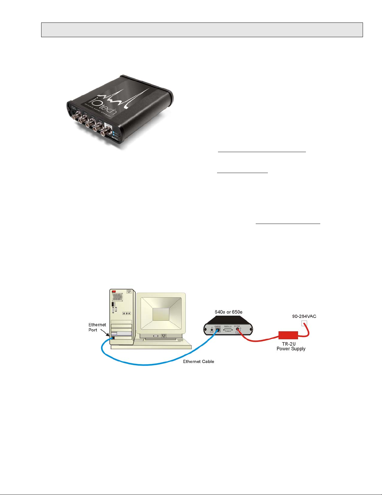
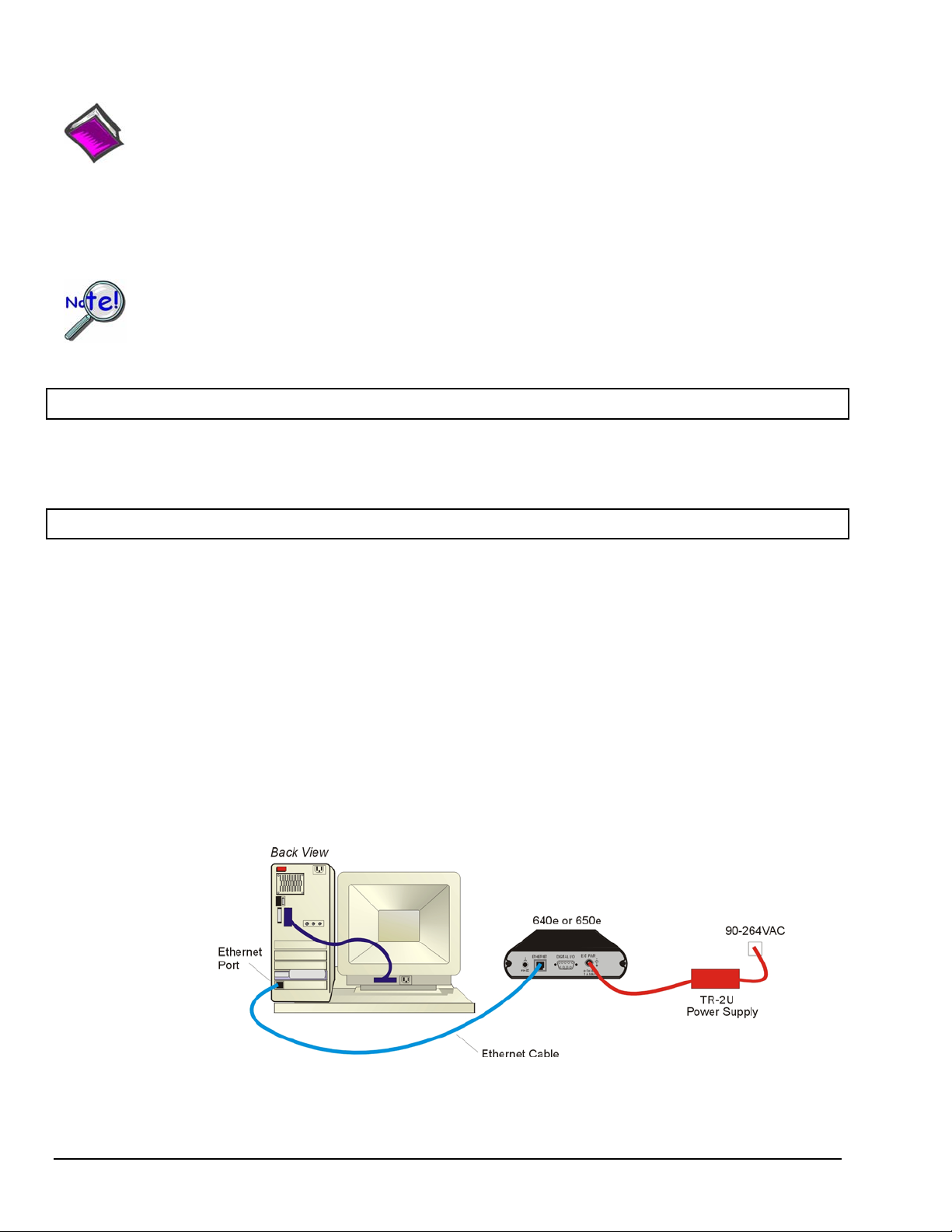
Step 2 - Connect the 640e or 650e to the Ethernet
In this scenario a 640e or 650e is connected directly to an Ethernet port on a host computer. Please consult your user’s
manual (located in PDF format on the CD) should you need information regarding the other network types.
1. Connect the Ethernet cable to the Ethernet jack on the 640e [or 650e].
2. Connect the other end of the Ethernet cable to the Ethernet jack on the host computer or network hub.
Step 3 - Connect the 640e or 650e to Power
1. Connect the power supply cable from the TR-2U to the External Power connector of the 640e [or 650e].
2. Connect the TR-2U plug to a standard AC outlet. The 640e [or 650e] Power LED will light up.
324539B-01
Page 10
Step 4 - Configure Computer Network Settings
Applies to “dedicated networks” only. See user’s manual in regard to other network types.
We recommend that you discuss this procedure with your Network Administrator before proceeding.
Note that the 640e and 650e Ethernet ports typically require 30 seconds after power-up [to configure]
before the unit can be accessed via the network.
1. Open the Control Panel by navigating from the Windows Desktop: Start Menu ⇒ Settings ⇒ Control Panel.
2. Double-click the “Network Connections” icon.
3. Double-click the icon for the network that the 640e [or 650e] is connected to.
4. In the “Local Area Connection Status” box, click on the <Properties> button.
The “Local Area Connection Properties” box will appear.
5. Double-click the “Internet Protocol (TCP/IP)” component.
The “Internet Protocol (TCP/IP) Properties” box will appear.
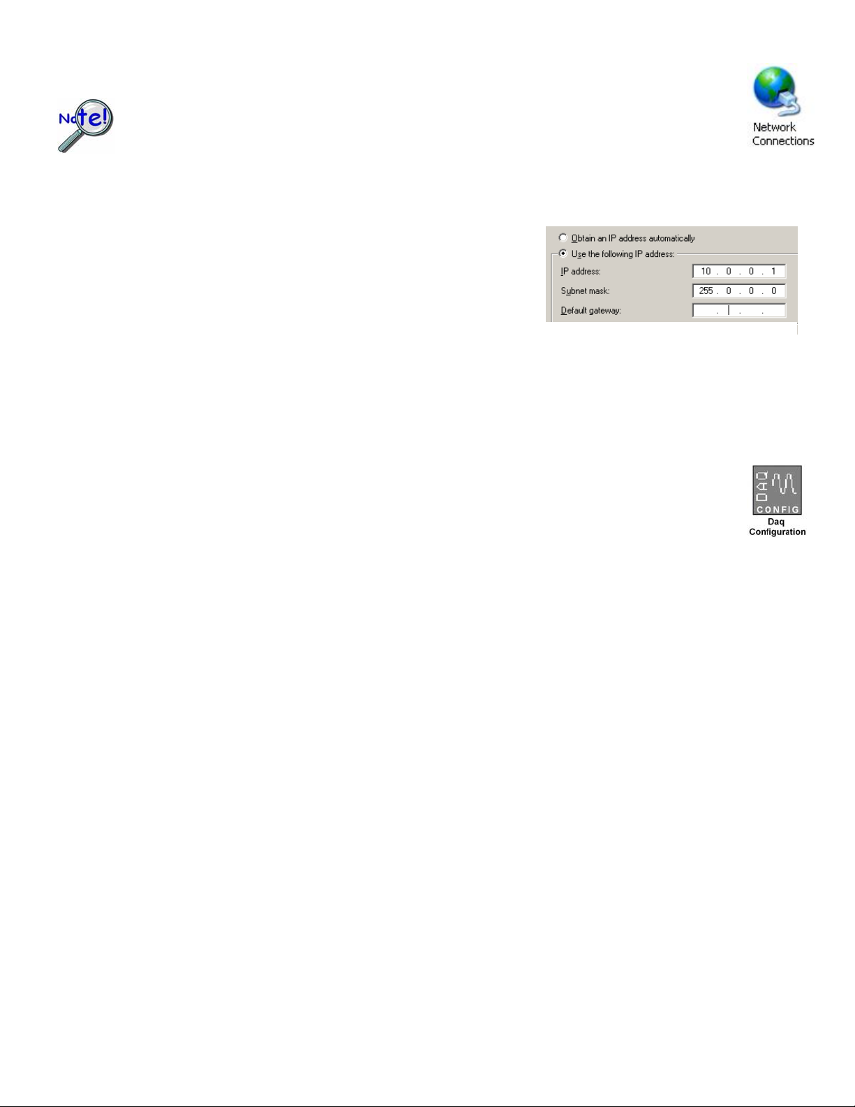
6. Select the “Use the following IP Address” radio button. (See figure at left).
7. Set the IP address field to 10.0.0.x , where x is some number from 1 to 254.
Make sure that each computer and each device on the dedicated network
has a unique IP address.
8. Set the Subnet mask to 255.0.0.0. Note that the remaining fields can be left as is.
9. Click <OK> on follow-up screens to exit.
Internet Protocol (TCP/IP) Properties
(Partial View)
Step 5 - Configure & Test the System with the Daq Configuration Applet
1. Open the Daq Configuration Applet.
a. Navigate from the Windows’ Desktop: Start Menu ⇒ Settings ⇒ Control Panel
b. From the Control Panel, double-click the Daq Configuration icon.
2. Add the 640e or 650e to the list of installed devices.
a. Click the <Add Device> button. The “Select Device Type” box will appear.
b. Select the 640e or 650e from the list of devices, as applicable.
c. Click the <OK> button. The “Properties” box will appear for the selected device.
d. Enter the Serial Number of the 640e [or 650e].
e. Select the “Auto IP Setting” radio button. The IP Address of the 640e [or 650e]
will be calculated automatically and displayed in the IP Address field.
3. Test the System.
a. Click the “Test Hardware” tab.
b. Click the <TCP/IP Test> button. This tests the Transmission Control Protocol / Internet Protocol.
c. Upon completion of the TCP/IP test, click the <Resource Test> button.
When testing, if the unit does not respond within 30 seconds perform the following steps:
1) reboot the system, 2) upon power-up, re-open the Daq Configuration applet,
3) select another configuration setting, 4) reinitiate the test.
Step 6 - Connect Data Acquisition Signal Lines
Prior to making signal connections review the Specifications chapter of your user’s manual to ensure that your intended
signal inputs do not exceed the specified limits. The manual is included in PDF format on your CD.
*324539B-01*
324539B-01
IOtech, 25971 Cannon Road, Cleveland, OH 44146-1833
Ph: (440) 439-4091 Fax: (440) 439-4093 productsupport@iotech.com Internet: www.iotech.com
Printed in Hungary
Page 11
IOtech 640u & 650u Quick Start
USB2.0 Dynamic Signal Analyzers for Vibration Analysis & Monitoring
Before you get started
verify that you have the following items.
•
640u or 650u
•
USB Cable
•
USB2.0 port
•
Dynamic Signal Analysis CD
•
License Keys for purchased software;
e.g., eZ-Analyst, eZ-TOMAS, eZ-Balance, eZ-NDT
Monitor: SVGA, 1024 x 768 screen resolution
•
•
Windows 2000 and Windows XP users:
ntel™ Pentium, 1 GHz or equivalent;
I
512 MB memory; 10 GB disk space
• Windows Vista users:
PC must be Windows Vista Premium Ready
Step 1 - Install Software
1. Close all running applications on the host PC.
2. Insert the Dynamic Signal Analysis CD into your CD-ROM drive and wait for the CD to auto-run. An Opening
Screen will appear. As an alternative, you can download software from:
[on PC]
www.iotech.com/ftp.html
3. Click the <ENTER SETUP> button.
Note: If you are downloading software from our website, follow instructions provided there.
4. From the hardware selection screen [which follows a licensing agreement], select the 640, 650 product-line
from the drop-down list and follow the on-screen instructions.
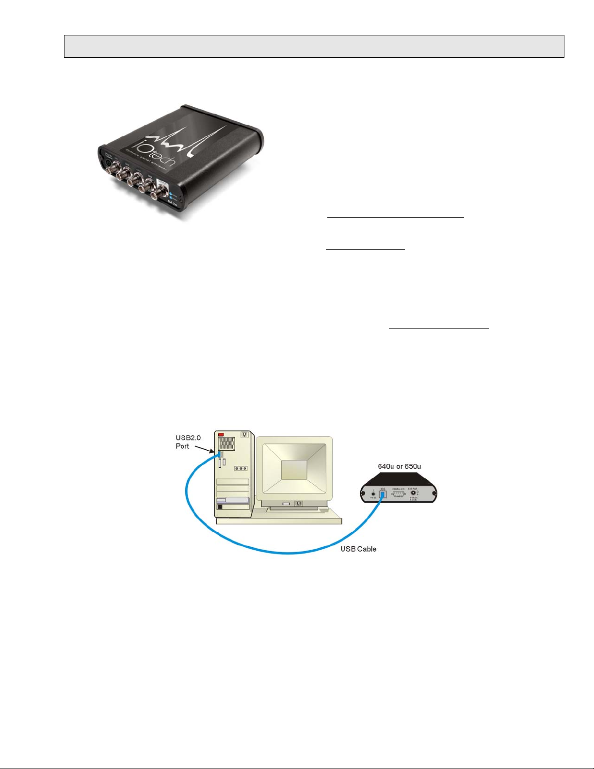
Step 2 - Connect the 640u or 650u to the Computer
1. Using a USB cable, connect the 640u [or 650u] to a USB2.0 port on the computer. USB2.0 port is required.
2. Follow the computer screen prompts as directed to allow the computer to detect your new hardware.
Note:
Power LED: The “Power” LED blinks during device detection and initialization; then remains on solid
as long as the module has power. If there is insufficient power the LED will go off.
Active LED: This LED is on whenever active communication is taking place between the 640 [or 650]
and the host PC. Note that the Active LED will be on solid during a data acquisition.
324540B-01
Page 12
Step 3 - Connect Data Acquisition Signal Lines Step 3 - Connect Data Acquisition Signal Lines
Prior to making signal connections review the Specifications chapter of your user’s manual to ensure that
Prior to making signal connections review the Specifications chapter of your user’s manual to ensure that
the input signals do not exceed the specified limits. The manual is included in PDF format on the CD.
the input signals do not exceed the specified limits. The manual is included in PDF format on the CD.
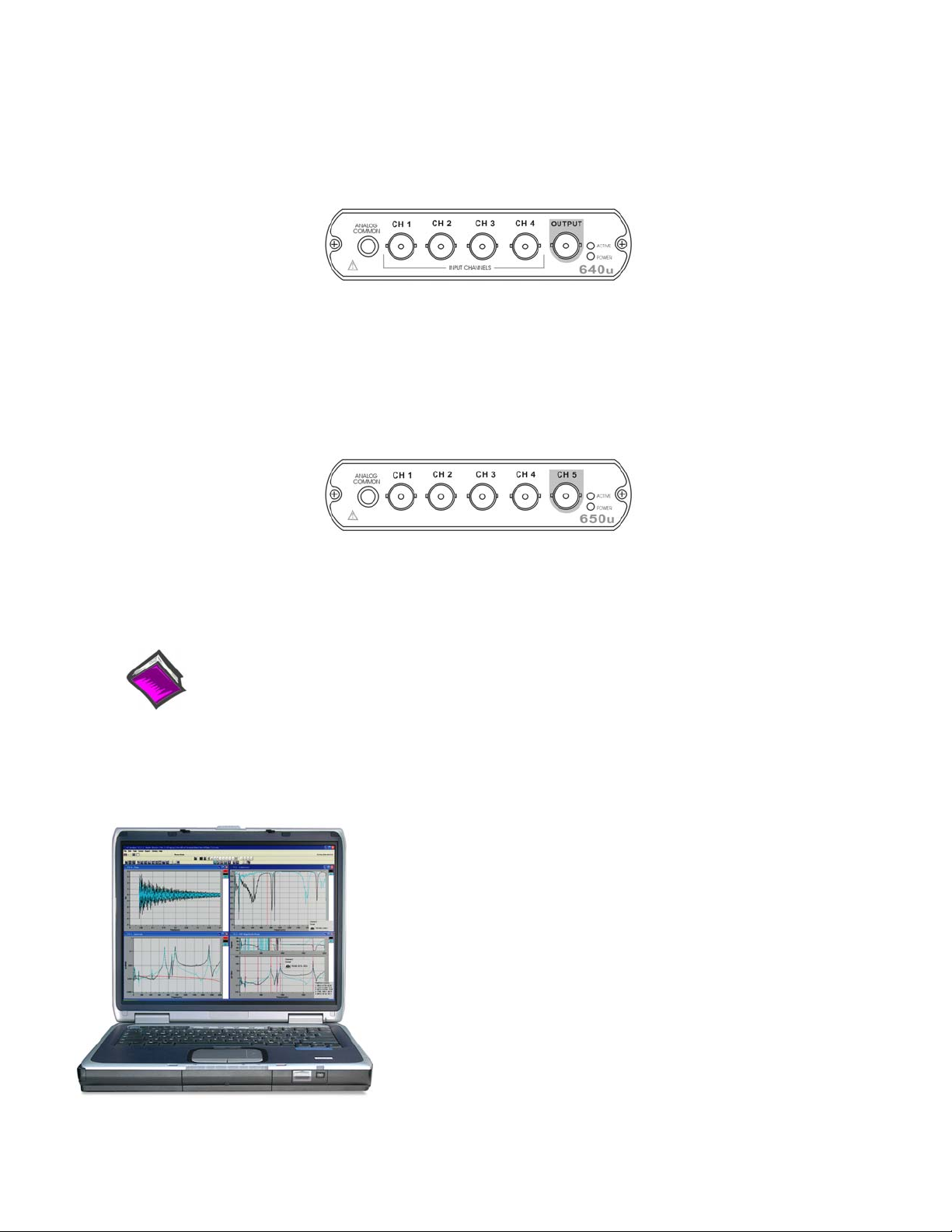
The 640u
The 640u
4 analog channel inputs (CH1 through CH4) via front panel BNC connectors.
1 analog output via the fifth front panel BNC connector.
8 digital I/O lines via rear panel DB9 connector, as discussed in Chapter 3 of the user’s manual.
The 650u
5 analog channel inputs (CH1 through CH5) via front panel BNC connectors.
8 digital I/O lines via rear panel DB9 connector, as discussed in Chapter 3 of the user’s manual.
Reference Notes:
Adobe Acrobat PDF versions of documents pertaining to IOtech 640u and 650u are automatically
installed onto your PC’s hard-drive as a part of product support at the time of software installation.
The default location is the Programs group. It can be accessed via the Windows Desktop Start
Menu.
E-mail: productsupport@iotech.com
IOtech, Inc.
25971 Cannon Road
Cleveland, OH 44146-1833
Phone: (440) 439-4091
Fax: (440) 439-4093
E-mail: sales@iotech.com
Internet: www.iotech.com
*324540B-01*
324540B-01
Printed in Hungary
Page 13
What are IOtech 640 and 650 Series Devices ? 1
* The actual model number includes an “e” or “u” to indicate Ethernet or USB version.
IOtech 640 and 650 Series Panels
IOtech 640 and 650 Series devices are dynamic signal analyzers used for monitoring and analyzing
machinery and structures in regard to sound, vibration, and rotation. The device hardware is the signal
conditioning and acquisition engine, while the software defines the specific analysis and monitoring
features of the system. Since the software [in the host PC] determines which capabilities will be used, it is
easy to upgrade the system and add more capabilities over time.
There are currently 4 models in the 640 and 650 product line. These are 640e, 640u, 650e, and 650u,
where
“e” indicates Ethernet Interface and “u” indicates USB2.0 Interface. The following matrix compares
model features.
Model Interface
640e
640u
650e
650u
Ethernet
10/100BaseT
USB2.0
Ethernet
10/100BaseT
USB2.0
Analog
Input
Channels
4 1.0 Hz ±10 V 1
5 0.1 Hz ±40 V 0
High Pass
Filter
Cutoff
Analog
Input
Range
Analog
Output
Channels
Digital I/O
Channels
8
External
Power
Connector
6 to 16 VDC
1 amp (max.)
There are four end-user software application packages available for IOtech 640 and IOtech 650 systems. A
brief description of each follows. For more information refer to Chapter 10, Software Options. For
detailed information refer to the specific software user’s manual. The data acquisition CD includes PDF
versions of the software documents.
eZ-Analyst
Used to record and analyze time history data; as well as perform impact (resonance)
testing.
eZ-TOMAS
Used to acquire, monitor, and analyze rotating machinery data for steady-state and
transient conditions.
eZ-Balance
eZ-NDT
Used to field balance multi-plane rotating machinery.
Used to determine the quality of production parts during the manufacturing process.
eZ-NDT is a non-destructive, resonance-based, testing process.
IOtech 640 & 650 Series 878893 What are IOtech 640 & 650 Series Devices? 1-1
Page 14

The IOtech 640e and 650e include a high-speed Ethernet engine powered by a PowerPC processor. The
640u and 650u include a high-speed USB2.0 engine. These Ethernet and USB interfaces allow all
acquired data to be transferred to the PC in real time at 630k samples/sec. This means that every acquired
data point can reside on the host PC’s hard drive, making re-creation and post acquisition analysis of
acquired data as precise as possible. Many other analyzers simply store frequency-domain information,
which results in play-back that is less precise than the original real-time measurement. In comparison, the
640 and 650 models transmit all time-domain measurements. This means there is no data loss when
analyzing acquired waveforms. Since the data is already on the host PC’s hard drive there is no time lost
transferring data.
Another advantage of the 640/650 architecture is that there is virtually no limit to the length of time
continuous data can be acquired. Many other systems do not offer continuous time-domain transfer to the
PC, and as a result the waveform length is limited by the amount of built-in data storage. In regard to
640/650 units, the only limitation is the amount of available hard disk memory on the host PC, or that
which can be accessed by a PC on a network.
• Features of the Dynamic Signal Inputs
o a current source for transducer biasing (ICP)
o detection of a transducer fault
o AC coupling: 0.1 Hz for IOtech 650 models; 1.0 Hz for IOtech 640 models; or DC coupling
o ±10 V range (IOtech 640 models)
o ±40 V range (IOtech 650 models)
o anti-aliasing filters: 3-pole low pass filter in hardware; set appropriately for each analysis rate
o pseudo-differential inputs
o support for TEDS (Transducer Electronic Data Sheet) in eZ-Analyst
o any analog input channel can serve as a tach input
o channel-to-channel phase matching
• For 640u and 650u - Easy Connection to USB2.0-ready Notebooks, Desktop PCs, or USB2.0 Hubs.
Note that the USB2.0 port allows a continuous stream of data to be collected and stored in the host PC.
• For 640e and 650e - Easy Connection to Ethernet-ready Notebooks, Desktop PCs, or Ethernet Hubs.
Note that the 10/100BaseT Ethernet port allows a continuous stream of data to be collected and stored
in the host PC.
• Analog Input Channels: BNC connectors.
• 8 Digital I/O Channels: DB9 connector for connection of Digital I/O signal lines.
Note: eZ-NDT or eZ-TOMAS software must be used to make use of the Digital I/O.
• Analog Channel Triggering
• Pre- and Post-Trigger Readings
1-2 What are IOtech 640 & 650 Series Devices? 878893 IOtech 640 & 650 Series
Page 15
Block Diagram and General Comments 2
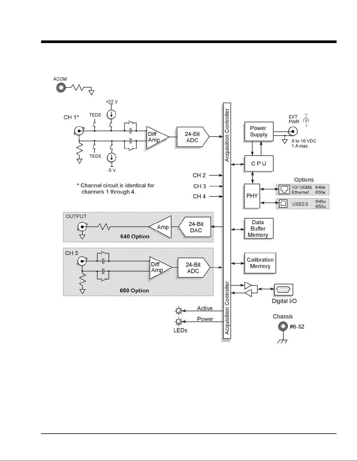
IOtech 640/650 Series Block Diagram
IOtech 640/650 Series 878893 Block Diagram 2-1
Page 16

General Comments
Ethernet Connection (640e and 650e models only)
IOtech 640e and 650e units transfer the acquired data to the PC via a 10/100BaseT Ethernet connection.
The Ethernet connection allows for a continuous stream of data to be collected and stored.
The 10/100BaseT Ethernet interface can be used in a point-to-point application, such as when attached to a
notebook PC and used in the field. In this case the 16 Mbytes of buffer storage built into the unit is
adequate to ensure that continuous data transfers to the PC can occur without risk of data loss.
The 10/100BaseT Ethernet interface can also be used to connect the unit to a network, presuming the
network has enough available bandwidth. The network bandwidth required is a function of the number of
signals being measured, and the bandwidth of the signals.
USB Connection (640u and 650u models only)
IOtech 640u and 650u units transfer the acquired data to the PC via a USB2.0 connection. When a
computer has a board with USB 2.0 ports, an “Enhanced” USB controller can be found in the Device
Manager. The Device Manager will also show two other USB controllers. This is due to the fact that
USB2.0 circuitry includes 3 chips [one for the actual USB2.0 capable devices and two for backward
USB1.1 compatibility]. Thus a USB 2.0 motherboard can host any USB device (version 2.0 or lower),
assuming there are no defects with the board, system, and/or device.
USB Notes:
o IOtech 640u and IOtech 650u require connection to USB2.0
o USB 1.1 (obsolete) hubs will work on USB 2.0 ports, but cannot utilize USB 2.0 capabilities.
o Hi-Speed and Full/Low-Speed USB devices can coexist on USB 2.0 hubs.
o USB 2.0 hubs can be used on computers with USB 1.1 ports, but will not exhibit USB 2.0
capabilities.
o Minimize hub use and keep USB cables as short as possible.
o Regardless of the USB hub or port used, if power to the 640u or 650u device is insufficient,
connect a TR-2U power adapter to the unit’s External Power jack.
Power
640e and 650e units can be powered directly from a 6 to 16 VDC source. They can also be powered from
a 100 to 250 VAC source via its power adapter, which converts the AC to the required DC.
640u and 650u units can be powered solely from a USB2.0 bus, or optionally from a 6 to 16 VDC source
via the external power connector.
LEDs 640 and 650 Series modules have 2 LEDs on the front panel. The LEDs function as follows:
Power LED: The “Power” LED blinks during device detection and initialization; then remains on solid
as long as the module has power. If there is insufficient power the LED will go off.
Active LED: This LED is on whenever active communication is taking place between the 640/650 and
the host PC. Note that the Active LED will be on solid during a data acquisition.
2-2 Block Diagram 878893IOtech 640/650 Series
Page 17

Digital I/O
To make use of the Digital I/O feature the 640 or 650 must be operating with eZ-TOMAS or eZ-NDT.
The 8-bits of digital I/O are provided via a rear panel DB9 connector. Each bit is programmable as
input or output.
Signal Conditioning
Every input to a 640 or 650 system is software programmable for AC/DC coupling, IEPE source [if AC
coupling is selected], and is capable of reading sensor calibration information using Transducer Electronic
Data Sheets (TEDS). eZ-Analyst software is required if the TEDS functionality is to be used.
When IEPE sensors are attached, AC coupling with bias current is selected via software. AC coupling
without bias is also possible for measuring any AC waveform. DC coupling, which is useful for proximity
sensor applications, can also be selected via the software.
For IEPE sensors, indication of an open or shorted fault is available within the eZ-Analyst software
application.
Source Output (640 units only)
640e and 640u each include one analog output channel capable of generating continuous waveforms.
These waveforms are programmable in regard to amplitude and frequency per product specifications.
They can be continuous sine, random, burst, or arbitrary.
IOtech 640/650 Series 878893 Block Diagram 2-3
Page 18

2-4 Block Diagram 878893IOtech 640/650 Series
Page 19
Connectors, Indicators, and Cables 3
Front Panel Connectors and Indicators …… 3-1
The Rear Pannel …… 3-2
Unit Underside …… 3-3
Accessories …… 3-4
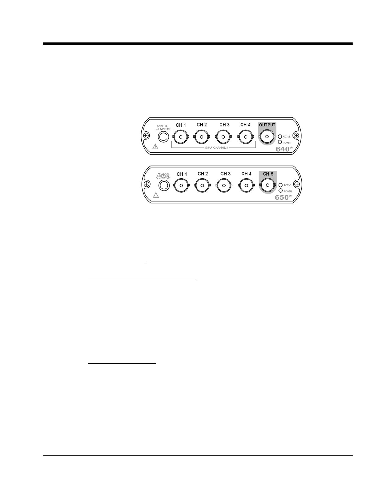
Front Panel Connectors and Indicators
640 and 650 Front Panels
The actual model number includes an “e” or “u” to indicate Ethernet or USB version.
*
The 640 and 650 Front Panels include the following connectors and LED indicators.
ANALOG COMMON
ANALOG SIGNAL INPUT CHANNELS
models have 4 input channels. The 650 models have 5 input channels.
The BNC center-conductor is the signal HI and the BNC shell is the signal LO. Each BNC shell is
connected to the chassis ground through its own channel-dedicated 1 kΩ resistor. Consequently, the shell
is not meant to be driven with respect to earth ground more than ±10V.
An additional consideration pertains to input transducer setup. If the transducer case is effectively earth
grounded through its connection to a device under test, there exists the possibility for added measurement
noise due to the ground loop that is created. The pseudo-differential input rejects much of this noise.
Electrically isolating the transducer from the test device minimizes noise.
OUTPUT (640 units only)
discrete amplitudes (see specifications). The output waveform parameters are controlled by software and
can be sine, swept-sine, random, burst, or arbitrary. The output can be used as a test source for the input
channels or as excitation for other system elements, such as the amplifier for a shaker table. Detailed
information on the excitation source and its operation can be found in the applicable eZ software
documentation, e.g., the eZ-Analyst User’s Manual.
: Common analog ground.
: These BNC connectors are used for voltage input. The 640
: The 640 units include a programmable voltage source that can be set in
NOTE: The output value is not guaranteed unless the Power LED has lit.
640 & 650 Series 878893 Connectors, Indicators, and Cables 3-1
Page 20
Status LEDs 640 and 650 Series modules have 2 LEDs on the front panel. The LEDs function as
follows:
Power LED: The “Power” LED blinks during device detection and initialization; then remains on solid as
long as the module has power. If there is insufficient power the LED will go off.
Active LED: This LED is on whenever active communication is taking place between the 640 or 650 and the
host PC. Note that the Active LED will be on solid during a data acquisition.
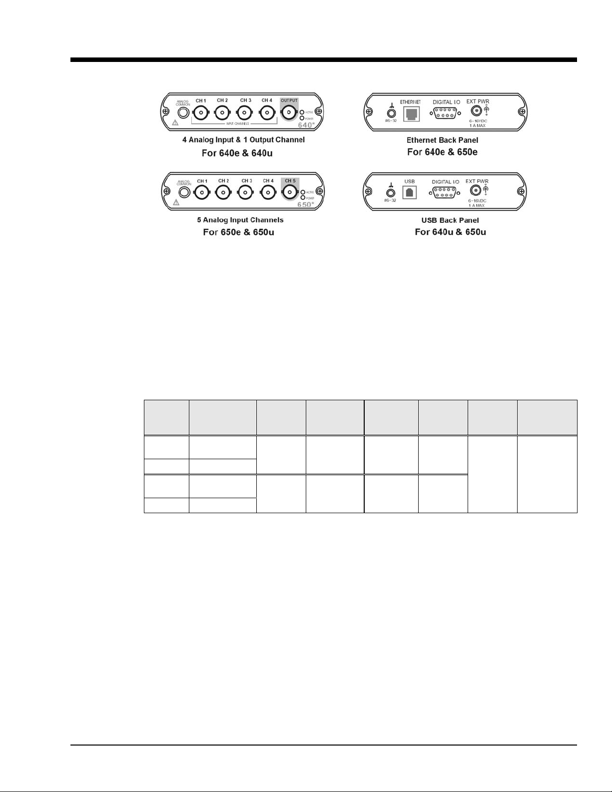
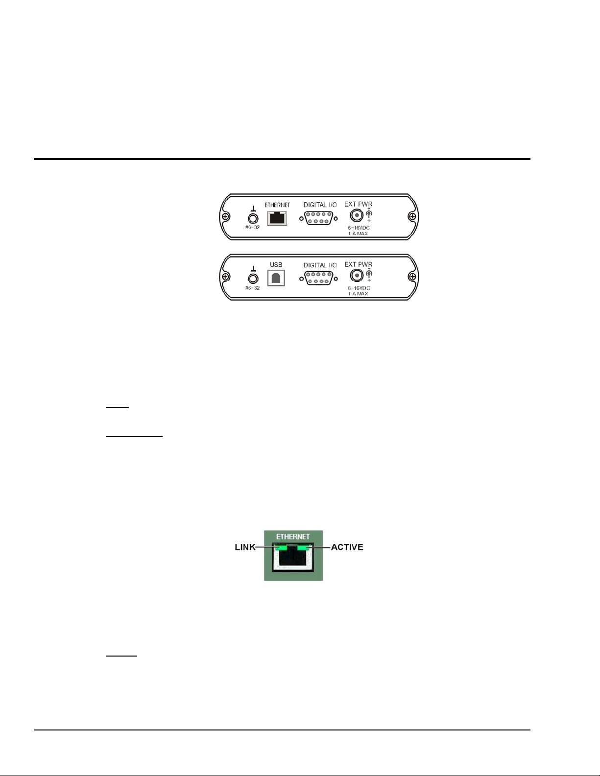
Rear Panel Connectors
Rear Panel for
640e & 650e
ETHERNET
Rear Panel for
640u & 650u
USB
IOtech 640 [or 650] Rear Panels
IOtech 640 and 650 “e” and “u” version rear panels are identical aside from their interface ports, with the
“e” versions being for Ethernet and the “u” versions being for USB. Both rear panels include a #6-32
chassis ground, a DB9-Digital I/O port, and an External Power connector.
: Provides a connection point for Chassis Ground via use of a #6-32 machine screw.
#6-32
ETHERNET
(Applies only to 640e and 650e): The 10/100BaseT Ethernet port can connect to the
Ethernet port of the host PC, or to an Ethernet network. Either of two Ethernet patch cables may be used to
make the connection. CA-242 is a 1.5 foot cable. CA-242-7 is a 7-foot cable. Note that the Ethernet
connector has two built in LEDs that indicate Ethernet status. These are discussed below. Note that the
Ethernet cable length must be <10m in order for the system to be CE Compliant.
Two rectangular ETHERNET Status LEDS (LINK and ACTIVE) are built
into the frame of the Ethernet jack.
LINK – “ON” indicates that a link via Ethernet exists.
ACTIVE – “ON” indicates that the port is receiving or transmitting traffic.
USB2.0
(Applies only to 640u and 650u): The USB port for 640u and 650u is intended for USB2.0 high-
speed (480Mbps). Chapter 2 includes information regarding USB2.0 and USB1.1. However, for these
units connection to a USB2.0 port on the host PC is required.
3-2 Connectors, Indicators, and Cables 878893 640 & 650 Series
Page 21
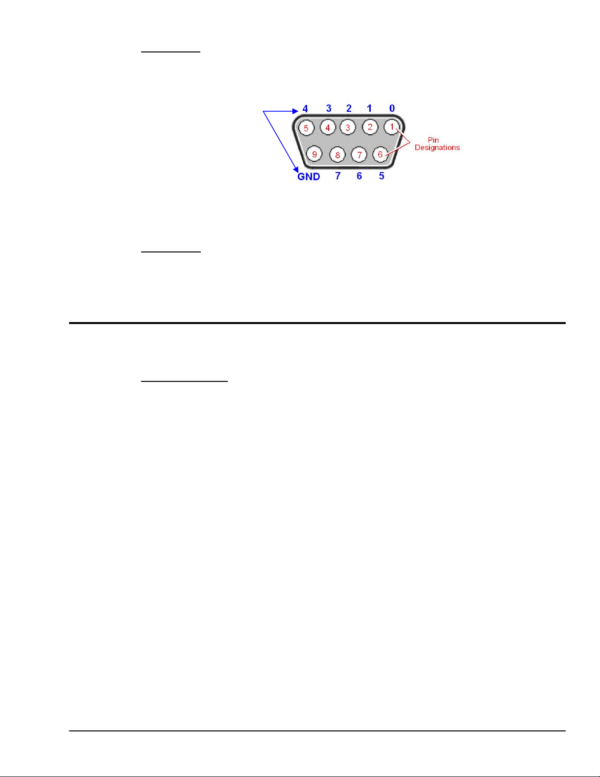
DIGITAL I/O: The units include a female DB9 connector for up to 8 Digital I/O lines. The connections
are designated as digital input or output via software. To make use of the Digital I/O feature, eZ-TOMAS
or eZ-NDT must be used. Refer to Chapter 8, Digital I/O and to the applicable software document for
details for additional information.
Digital I/O
Channel
EXT POWER
adapter.
Unit Underside
MAC Address Label
shows the device serial number in barcode and base 10 formats. It also shows the Ethernet address (MAC
Address) which is derived from the serial number in hexadecimal and is needed for 640e and 650e models.
If prompted to enter a serial number in software, use the base 10 number. Conversion to a hexadecimal
number for use in addressing will be automatic.
Note: If your network administrator asks you for a MAC number or MAC Address,
provide the hexadecimal number that is located at the bottom of the label.
DB9 – As viewed from the rear panel
: +6 to +16 VDC, 1 amp maximum. Power is typically supplied from a TR-2U power
: Located on the bottom of the chassis, the Media Access Control (MAC) label
640 & 650 Series 878893 Connectors, Indicators, and Cables 3-3
Page 22

Accessories
CA-242 or CA-242-7 Ethernet Patch Cable
CA-242 is a 1.5 foot cable that can be used to connect an IOtech 640e or 650e to an Ethernet port on a PC or
network. CA-242-7 is a 7-foot cable that can be used for the same purpose.
CA-179-1, -3, or -5 High-Speed USB Cable
CA-179-x cables can be used to connect an IOtech 640u or 650u to a USB port on a PC or USB hub.
The -1, -3, and -5 cables are 1m, 3m, and 5m in length, respectively.
TR-2U Power Supply
TR-2U is an AC-to-DC conversion power supply. TR-2U plugs into the External Power connector of the
IOtech 640 or 650 unit.
TR-2U Ratings:
o Input voltage to TR-2U: 90-264 VAC
o TR-2U voltage output (supply to device): 9VDC
o Max Current Output: 1.7 amp
3-4 Connectors, Indicators, and Cables 878893 640 & 650 Series
Page 23

Configuring Ethernet Models 640e & 650e 4
System Requirements …… 4-1
Software Installation …… 4-2
Ethernet Connection and System Power-up …… 4-3
Connecting Data Acquisition Signal Lines …… 4-14
Purchased software packages such as eZ-Analyst and eZ-TOMAS are shipped with a
license key. Keep your key(s) in a safe place. You will need to enter them during the
initial run of your purchased software.
System Requirements
Before setting up the hardware or installing the software, verify that you have the following items.
• 640e or 650e
• TR-2U Power Supply
• Ethernet Patch Cable
• Dynamic Signal Analysis CD for 600 Series Devices
• License Keys for purchased software; e.g., eZ-Analyst, eZ-TOMAS, eZ-Balance, eZ-NDT
• Computer that meets or exceeds the following:
• Monitor: SVGA, 1024 x 768 screen resolution
o Intel
o Microsoft
o 512 MB memory
o 10 GB disk space
o An Ethernet jack [on the computer or on a hub connected to the Ethernet]
™
Pentium, 1 GHz or equivalent
®
Windows XP, 2000, or Vista Operating System
640 & 650 Series 878893 Configuring Ethernet Models 640e & 650e 4-1
Page 24

Software Installation
Remove any previous-installed versions of your application software (eZ-Analyst,
eZ-TOMAS, eZ-Balance, or eZ-NDT) before installing a new version.
1. Start Windows.
2. Close all running applications.
3. Insert the Data Acquisition CD into your CD-ROM drive and wait for the CD to auto-run.
If the CD does not start on its own:
An Opening Screen will appear.
4. Click the <ENTER SETUP> button.
5. From the hardware selection screen [which follows a licensing agreement], select
640e or 650e from the drop-down list and follow the on-screen instructions.
(a) click the desktop’s <Start> button
(b) choose the Run command
(c) select the CD-ROM drive, then select the setup.exe file.
(d) click <OK>
Reference Notes:
Adobe Acrobat PDF versions of documents pertaining to IOtech 640 and 650 are
automatically installed onto your PC’s hard-drive as a part of product support at the time of
software installation. The default location is the Programs group, which can be accessed
via the Windows Desktop Start Menu.
4-2 Configuring Ethernet Models 640e & 650e 878893 640 & 650 Series
Page 25

Ethernet Connection and System Power-up
As this document goes to print, Ethernet connectivity can only be used with
Windows 2000 or Windows XP operating systems.
Overview
640e or 650e, Rear Panel
IOtech 640e and 650e connect directly to an Ethernet port on a PC or network hub, via the unit’s built-in
10/100BaseT Ethernet interface. An Ethernet patch cable CA-242 (1.5 foot) or CA-242-7 (7 foot) cable is
used to make the connection. Note that either a straight-through or a cross-over cable may be used. The
circuitry automatically adjusts for the cable type to ensure proper connection.
Connecting an IOtech 640e or 650e to the Ethernet
CAUTION
Turn off power to the system devices and externally connected equipment before connecting cables.
Electric shock or damage to equipment can result even under low-voltage conditions.
Take ESD precautions (packaging, proper handling, grounded wrist strap, etc.)
640 & 650 Series 878893 Configuring Ethernet Models 640e & 650e 4-3
Page 26
Reference Note:
Adobe PDF versions of user manuals will automatically install onto your hard drive as a part of product
support. The default location is in the Programs group, which can be accessed from the Windows Desktop.
You can also access documents directly from the data acquisition CD via the <View PDFs> button located on
the CD’s opening screen.
Contact the factory or your service representative in regard to Ethernet connectivity if
your operating system is other than Windows 2000 or Windows XP.
STEP 1 – Install the Software
Install the software prior to connecting the 640e or 650e to the Ethernet. If you have not already installed the software,
do so at this time. Refer to the section entitled Software Installation, page 4-2.
STEP 2 – Determine the type of Network Connection
To properly connect and configure a 640e or 650e, you must determine the type of network that the device
will become part of. This is because the type of network used has a direct bearing on the IP address of the
device.
Briefly, the four network types are as follows:
• Dedicated Network - with a direct cable connection from the PC to the device
• Dedicated Network - making use of a network hub or switch
• LAN with a DHCP server
(Local Area Network with a Dynamic Host Configuration Protocol)
• LAN without a DHCP server
(Local Area Network with no Dynamic Host Configuration Protocol)
Brief descriptions and illustrations follow.
Dedicated Network - with a direct cable connection from the PC to the device
In this scenario a 640e or 650e is connected directly to an Ethernet port on a host computer.
Dedicated Network using a Direct Cable Connection
4-4 Configuring Ethernet Models 640e & 650e 878893 640 & 650 Series
Page 27
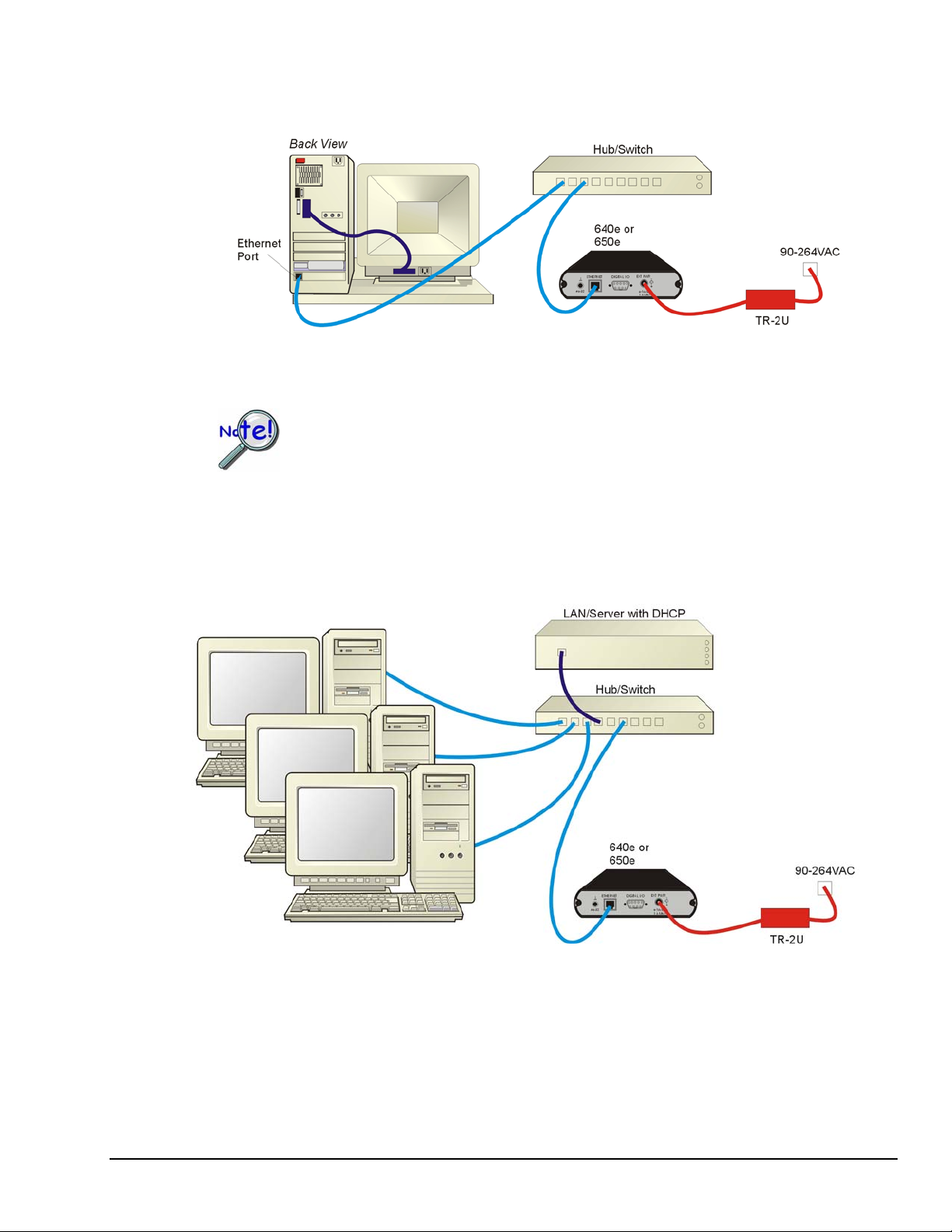
Dedicated Network - making use of a network hub or switch
In this scenario the 640e or 650e connects to the Ethernet through a network hub or switch. At least one
computer is also connected to the hub.
Dedicated Network using a Hub/Switch
Some network devices such as a wireless access point may act as a DHCP server. If this is
the case, follow the instructions for the LAN with a DHCP server. For detailed
information consult the documentation that is specific to your network device.
LAN with a DHCP Server (Local Area Network with a Dynamic Host Configuration Protocol server)
Many corporations use the LAN/Server with DHCP arrangement for their networks. In this type of setup
several computers are typically connected to a network that makes use of a DHCP server. In addition, a
640e or 650e is connected to the network hub/switch.
LAN with a DHCP Server
Notes:
¾ Using a 640e or 650e on a typical LAN may affect the speed of the network and internet data
transfer. Because of this we recommend adding a network card to the computer and using one of
the two dedicated network configurations.
¾ Contact your network administrator before connecting a 640e or a 650e to a corporate network.
640 & 650 Series 878893 Configuring Ethernet Models 640e & 650e 4-5
Page 28

LAN with no DHCP Server
(Local Area Network with no Dynamic Host Configuration Protocol server)
This scenario looks the same as that shown in the previous illustration, except there is no Dynamic Host
Configuration Protocol (DHCP). In this type of setup, one or more computers are connected to a network;
and each computer has a static IP address.
STEP 3 – Connect the System Components
What you will need to connect a 640e or a 650e to the Ethernet
• An available connection to the Ethernet. The connection can be either
- an Ethernet jack on a computer or
- an Ethernet jack on a hub that is connected to the Ethernet.
• An Ethernet patch cable, e.g., a CA-242 (1.5 foot cable) or a CA-242-7 (7-foot cable).
1. Connect the Ethernet cable to the Ethernet jack on the 640e or the 650e.
2. Connect the other end of the Ethernet cable to the Ethernet jack on the host computer or
network hub.
:
STEP 4 – Power-up the System Components
What you will need
A power supply with a range of 6 to 16 VDC. We recommend the TR-2U power supply.
How to make the connection:
1. Connect the power supply cable, e.g., from the TR-2U, to the External Power connector on the
rear panel of the 640e or 650e.
2. Connect the power supply’s plug to a standard AC outlet.
3. If you are using a power supply with a power switch, position it to “ON.”
4. The 640e or 650e Power LED will light up.
:
4-6 Configuring Ethernet Models 640e & 650e 878893 640 & 650 Series
Page 29
STEP 5 - Configure the Computer’s Network Settings [Applies to “dedicated networks” only]
The 640e and 650e Ethernet ports typically require 30 seconds after power-up to configure,
before the unit can be accessed via the network.
If using a LAN (Local Area Network), which has a DHCP server
, skip this section and continue
with STEP 7 - Configure and Test the System using the Daq Configuration Applet (page 4-11).
If using a LAN (Local Area Network), which has no DHCP server
, skip this section and
continue with STEP 6 - Configure Device Network Settings using DaqIPConfig (page 4-10).
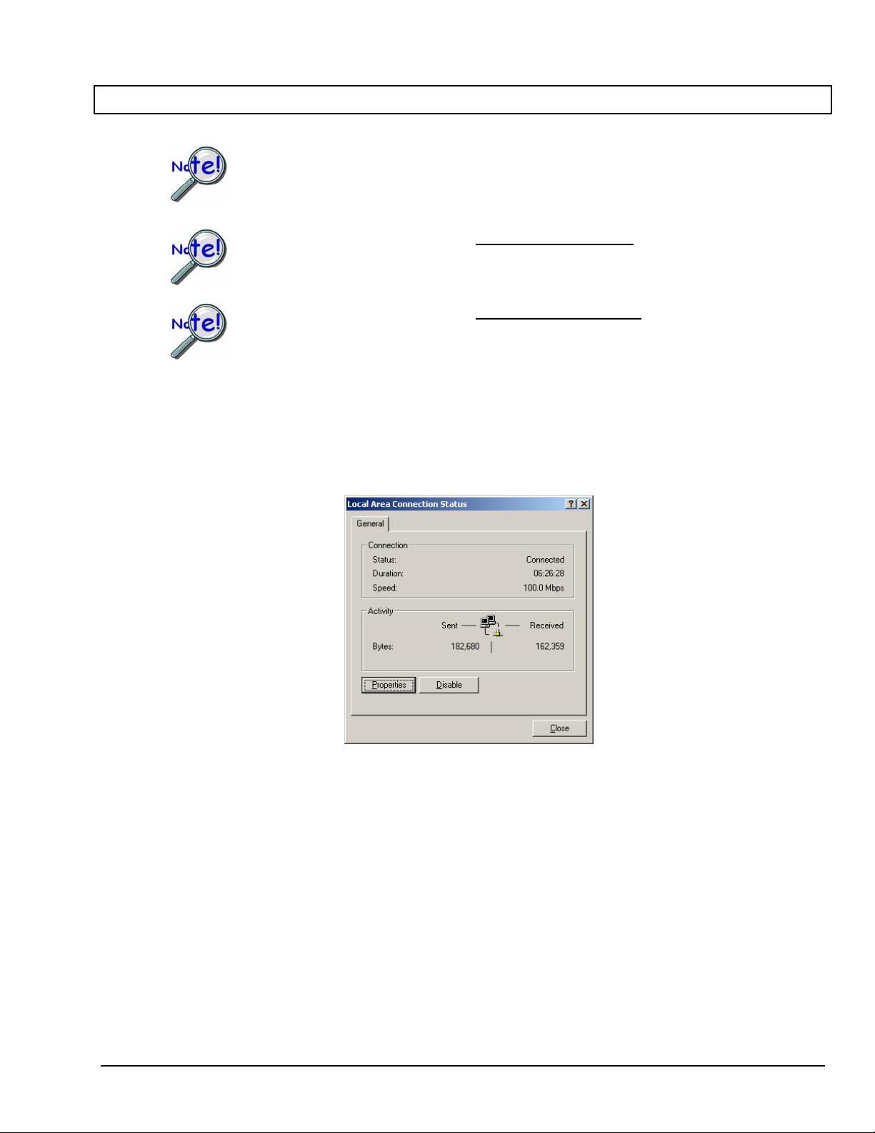
1. Open the Control Panel by navigating from the Windows Desktop as follows:
Start Menu ⇒ Settings ⇒ Control Panel.
2. Double-click the “Network and Dial-up Connections” icon.
3. Double-click the “Network Connection” icon for the network that the 640e or 650e is connected to.
Local Area Connection Status
640 & 650 Series 878893 Configuring Ethernet Models 640e & 650e 4-7
Page 30
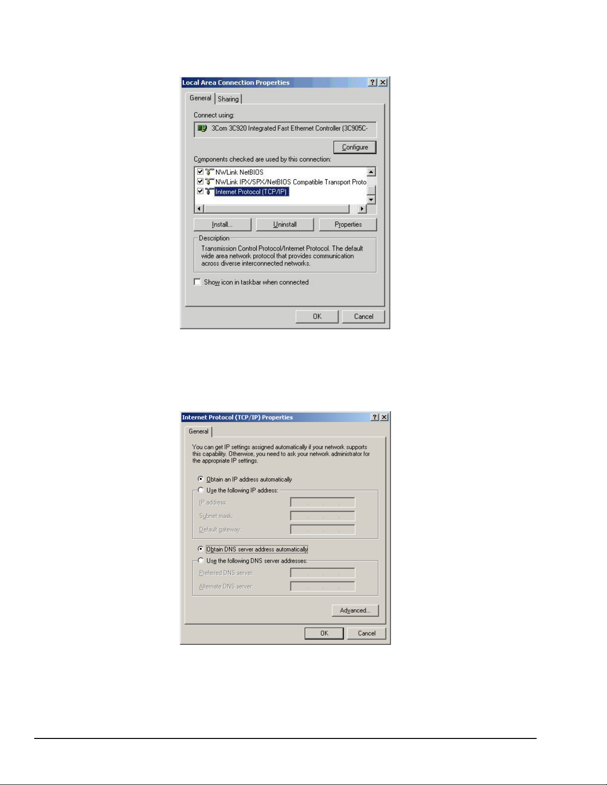
4. In the “Local Area Connection Status” box (previous figure), click on the <Properties> button.
The “Local Area Connection Properties” box will appear (following figure).
Local Area Connection Properties
5. Double-click the “Internet Protocol (TCP/IP)” component (previous figure).
The “Internet Protocol (TCP/IP) Properties” box will appear (following figure).
Internet Protocol (TCP/IP) Properties
4-8 Configuring Ethernet Models 640e & 650e 878893 640 & 650 Series
Page 31

Configure the Computer’s TCP/IP settings as follows.
Internet Protocol (TCP/IP) Properties
6. Select the “Use the following IP Address” radio button.
7. Set the IP address field to 10.0.0.x where x is some number from 1 to 254.
Make sure that each computer on the dedicated network has a unique IP address.
8. Set the Subnet mask to 255.0.0.0. Note that the remaining fields can be left unchanged.
640 & 650 Series 878893 Configuring Ethernet Models 640e & 650e 4-9
Page 32

STEP 6 - Configure Device Network Settings using DaqIPConfig
Applies only to a LAN (Local Area Network), which has a no DHCP server.
If using a LAN (Local Area Network), which has a DHCP server
, skip this section and continue
with STEP 7 - Configure and Test the System using the Daq Configuration Applet (page 4-11).
Multiple devices on a LAN are each identified by their unique (device-specific) serial number.
Ensure that the serial number displayed for the unit [being configured] agrees with the serial
number on the MAC label, located on the rear panel of the device.
The DaqIPConfig applet, designed for 32-bit Windows /2000/XP systems. DaqIPConfig allows you to change the
IP address of a device to match the address of a host computer. The applet is located in the program group for the
associated device and can be accessed from the Windows Desktop via the start menu.
Reference Note:
Appendix A contains general information regarding how to use the Daq Configuration Applet.
1. Locate the DaqIPConfig Applet.
Locate the DaqIPConfig applet by navigating from the
Windows’ Desktop as follows:
Start Menu
⇒ Programs
⇒ IOtech Application Software
IOtech eZ-Analyst Software, IOtech eZ-TOMAS Software, etc.
; for example:
⇒ DaqIPConfig
2. Open the DaqIPConfig Applet.
Click on the DaqIPConfig selection to open the applet.
3. Select the Device Type that is to have the address
change.
Note: In the figure to the right 650e is selected.
4. Set the internet protocol (TCP/IP) settings to be
compatible with host computer.
(a) Select the radio button labeled “Use the following IP
address.”
(b) Enter the new internet protocol settings. If needed,
consult your network administrator for acceptable
DaqIPConfig
numbers.
Do not set the TCP/IP to the
computer’s IP address.
(c) Click the <OK> button.
5. Reboot the device.
The new IP address will not take affect until the device has been powered-off, then powered back on.
6. Repeat steps 3, 4, and 5 for other devices in the system.
After configuring the network settings for all devices, proceed to Step 7.
4-10 Configuring Ethernet Models 640e & 650e 878893 640 & 650 Series
Page 33

STEP 7 - Configure and test the System using the Daq* Configuration Applet
The Daq* Configuration applet, designed for 32-bit systems, is located in the Windows Control Panel. It
allows you to add or remove a device and change configuration settings. The included test utility provides
feedback on the validity of current configuration settings, as well as performance summaries.
1. Open the Daq* Configuration Applet.
a. Open the Control Panel by navigating from the Windows’ Desktop as follows:
Start Menu ⇒ Settings ⇒ Control Panel
b. From the Control Panel, double-click the Daq* Configuration icon.
2. Add the first-level device to the list of installed devices.
The first-level device is the device that will be connected directly to the Ethernet, via a host computer’s
Ethernet jack or a jack on a network hub. The 640e and 650e are first-level devices.
a. Select the Computer image in the Device Inventory configuration tree (following figure).
b. Click the <Add Device> button. The “Select Device Type” box will appear.
c. Select the 640e or 650e from the list of devices, as applicable.
d. Click the <OK> button. The “Properties” box will appear for the selected device.
Using Daq Configuration Device Inventory & Select Device Type to Add a Device
640 & 650 Series 878893 Configuring Ethernet Models 640e & 650e 4-11
Page 34

3. Set the properties of the first-level device.
In this step you will set the device properties according to one of the following two methods, depending on
whether you have a “Dedicated Network” or a “LAN with DHCP Server Network.”
Users of Dedicated Networks
a. Enter the Serial Number of the 640e or 650e. In the following screen shots the Serial
Number is 800427.
b. Select the “Auto IP Setting” radio button. Note that the IP Address of the 640e or 650e will
be calculated automatically and displayed in the IP Address field as indicated in the following
left-hand figure.
c. Click the <OK> button.
follow these 2 steps.
For DEDICATED
Networks For LAN with DHCP Server Networks
Daq* Configuration, Properties Dialog Boxes
Users of LAN with DHCP Server Networks
follow these 3 steps.
The DaqIPConfig applet provides the Serial Number and the IP Address of the device. Users of LAN
with DHCP Server Networks will need to enter both numbers in the Daq* Configuration, Properties
dialog boxes (previous right-hand figure). Page 4-10 includes instructions for accessing DaqIPConfig.
If needed, refer to the upper right-hand figure in regard to
radio-button and data entry locations.
a. Enter the base 10 version of the Serial Number of
the 640e or 650e.
b. Select the “Manual IP Setting” radio button.
c. In the IP Address field, enter the IP address.
d. Click the <OK> button.
Partial View of DaqIP Config
Showing IP Address & Serial Number
Provide your network administrator with the information on the device’s MAC label.
Also, find out from the administrator if the IP Address will be changing. If so, see if
you can obtain a permanent IP Address dedicated specifically to your device.
4-12 Configuring Ethernet Models 640e & 650e 878893 640 & 650 Series
Page 35

4. Test the system connections.
a. Make sure the device has been properly installed and is powered-on.
b. Make sure all cables are properly and securely connected.
c. Click the “Test Hardware” tab.
d. Click the <TCP/IP Test> button. This tests the Transmission Control Protocol / Internet
Protocol.
The TCP/IP
test results have two components: Pinging Device and TCP Connection.
Appendix B, TCP/IP and Resource Tests, includes a brief explanation of each.
e. Upon completion of the TCP/IP test, click the <Resource Test> button.
The Resource Test consists of two components: Resource Tests and Performance Tests.
Appendix B, TCP/IP and Resource Tests, includes a brief explanation of each.
When testing a 640e or a 650e, if the unit does not respond after 30 seconds perform the
following steps:
1) reboot the system
2) upon power-up, re-open the Daq* Configuration applet
3) select another configuration setting
4) reinitiate the test
This completes the procedure for connecting an IOtech 640e or 650e to the Ethernet. At this point you
should refer to the following section regarding signal lines.
Note: You can access PDF documents directly from the opening screen of the data acquisition CD
via the <View PDFs> button.
640 & 650 Series 878893 Configuring Ethernet Models 640e & 650e 4-13
Page 36

Connecting Data Acquisition Signal Lines
Prior to making signal connections review the Specifications chapter to ensure that signal inputs do not
exceed the specified limits.
The 640e
4 analog channel inputs (CH1 through CH4) via front panel BNC connectors.
1 analog output via a front panel BNC connector.
8 digital I/O lines via rear panel DB9 connector, as discussed in Chapter 3,
Connectors, Indicators, and Cables.
The 650e
5 analog channel inputs (CH1 through CH5) via front panel BNC connectors.
8 digital I/O lines via rear panel DB9 connector, as discussed in Chapter 3,
Connectors, Indicators, and Cables.
4-14 Configuring Ethernet Models 640e & 650e 878893 640 & 650 Series
Page 37

Configuring USB Models 640u & 650u 5
System Requirements …… 5-1
Software Installation …… 5-2
USB Connection and System Power-up …… 5-3
Connecting Data Acquisition Signal Lines …… 5-6
Purchased software packages such as eZ-Analyst and eZ-TOMAS are shipped with a
license key. Keep your key(s) in a safe place. You will need to enter them during the
initial run of your purchased software.
System Requirements
Before setting up the hardware or installing the software, verify that you have the following:
• 640u or 650u
• USB Cable
• Dynamic Signal Analysis CD for 600 Series Devices
• License Keys for purchased software; e.g., eZ-Analyst, eZ-TOMAS, eZ-Balance, eZ-NDT
• Computer that meets or exceeds the following:
o Intel
o Microsoft
o USB2.0 port
o 512 MB memory
o 10 GB disk space
• Monitor: SVGA, 1024 x 768 screen resolution
™
Pentium, 1 GHz or equivalent
®
Windows XP, 2000, or Vista Operating System
640 & 650 Series 889793 Configuring USB Models 640u & 650u 5-1
Page 38

Software Installation
Remove any previous-installed versions of your application software (eZ-Analyst,
eZ-TOMAS, eZ-Balance, or eZ-NDT) before installing a new version.
1. Start Windows.
2. Close all running applications.
3. Insert the Data Acquisition CD into your CD-ROM drive and wait for the CD to auto-run.
If the CD does not start on its own:
An Opening Screen will appear.
4. Click the <ENTER SETUP> button.
5. From the hardware selection screen [which follows a licensing agreement], select
640u or 650u from the drop-down list and follow the on-screen instructions.
(a) click the desktop’s <Start> button
(b) choose the Run command
(c) select the CD-ROM drive, then select the setup.exe file.
(d) click <OK>
Reference Notes:
Adobe Acrobat PDF versions of documents pertaining to IOtech 640 and 650 are
automatically installed onto your PC’s hard-drive as a part of product support at the time of
software installation. The default location is the Programs group, which can be accessed
via the Windows Desktop Start Menu.
5-2 Configuring USB Models 640u & 650u 889793 640 & 650 Series
Page 39

USB Connection and System Power-up
As this document goes to print, USB connectivity can only be used with
Windows 2000 or Windows XP operating systems.
Overview
IOtech 640u and 650u units transfer the acquired data to the PC via a USB2.0 connection. When a
computer has a board with USB 2.0 ports, an “Enhanced” USB controller can be found in the Device
Manager. The Device Manager will also show two other USB controllers. This is due to the fact that
USB2.0 circuitry includes 3 chips [one for the actual USB2.0 capable devices and two for backward
USB1.1 compatibility]. Thus a USB 2.0 motherboard can host any USB device (version 2.0 or lower),
assuming there are no defects with the board, system, and/or device.
USB Notes:
o IOtech 640u and IOtech 650u require connection to USB2.0
o USB 1.1 (obsolete) hubs will work on USB 2.0 ports, but cannot utilize USB 2.0 capabilities.
o Hi-Speed and Full/Low-Speed USB devices can coexist on USB 2.0 hubs.
o USB 2.0 hubs can be used on computers with USB 1.1 ports, but will not exhibit USB 2.0
capabilities.
o Minimize hub use and keep USB cables as short as possible.
o If you do not want to power the 640u or 650u from a USB2.0 port, connect a TR-2U power
adapter to the unit’s External Power jack.
640u or 650u, Rear Panel
IOtech 640u and 650u connect directly to a USB port on the PC [or USB2.0 hub] via the unit’s built in
USB2.0 interface. A CA-179-1 (or -3, or -5) USB cable is used to make the connection.
CAUTION
Turn off power to the system devices and externally connected equipment before connecting cables.
Electric shock or damage to equipment can result even under low-voltage conditions.
Take ESD precautions (packaging, proper handling, grounded wrist strap, etc.)
640 & 650 Series 889793 Configuring USB Models 640u & 650u 5-3
Page 40

Reference Note:
Adobe PDF versions of user manuals will automatically install onto your hard drive as a part
of product support. The default location is in the Programs group, which can be accessed
from the Windows Desktop. You can also access documents directly from the data acquisition
CD via the <View PDFs> button located on the CD’s opening screen.
Contact the factory or your service representative in regard to USB connectivity if
your operating system is other than Windows 2000 or Windows XP.
Making Power and USB Connections
1. If using an optional TR-2U power supply, connect it to the 640 or 650 unit’s External Power
(EXT PWR) connector; then plug the TR-2U into an outlet which supplies 90 to 264 VAC.
The use of a TR-2U
is optional.
Do not connect the CA-179-x USB cable until after the Power Supply is supplying power to the
640u or 650u. (See following note.)
The use of a TR-2U is optional. If using one, be sure to supply power from the TR-2U to
the 640u or 650u before connecting the USB cable to the computer. This allows the 640u
[or 650u] to inform the host computer (upon connection of the USB cable) that the unit
requires minimal power from the computer’s USB port. When removing the unit from the
PC, the TR-2U power cable must be removed after the USB cable is unplugged.
2. Use a CA-179-1 (or -3, or -5) USB cable to connect the 640u or 650u device to a USB2.0 port on the
computer. USB2.0 port is required.
3. Follow the screen prompts as directed.
LED Note: 640 and 650 Series modules each have 2 LEDs on their front panel.
The LEDs function as follows:
Power LED: The “Power” LED blinks during device detection and initialization; then remains on solid
as long as the module has power. If there is insufficient power the LED will go off.
Active LED: This LED is on whenever active communication is taking place between the 640 [or 650] and
the host PC. Note that the Active LED will be on solid during a data acquisition.
5-4 Configuring USB Models 640u & 650u 889793 640 & 650 Series
Page 41

If you need to find the name of your device for any reason, you can do so by navigating from the
Windows Desktop to the Device Manager. The navigation path is:
StartÖSettingsÖControl PanelÖSystemÖHardware(Tab) ÖDevice Manager
ÖDaqX PnP Devices
You will see the device listed in the format of 640u or 650u (see first figure, below).
You can change the name of the device by doing a right-click on the device name to open its properties
dialog box, then clicking on the Properties tab (see second figure). You can then change the
“FriendlyName” of the device.
Locating DaqXPnP Devices
Properties Dialog Box
640 & 650 Series 889793 Configuring USB Models 640u & 650u 5-5
Page 42

Connecting Data Acquisition Signal Lines
Prior to making signal connections review the Specifications chapter to ensure that signal inputs do not
exceed the specified limits.
The 640u
4 analog channel inputs (CH1 through CH4) via front panel BNC connectors.
1 analog output via the fifth front panel BNC connector.
8 digital I/O lines via rear panel DB9 connector, as discussed in Chapter 3,
Connectors, Indicators, and Cables.
The 650u
5 analog channel inputs (CH1 through CH5) via front panel BNC connectors.
8 digital I/O lines via rear panel DB9 connector, as discussed in Chapter 3,
Connectors, Indicators, and Cables.
5-6 Configuring USB Models 640u & 650u 889793 640 & 650 Series
Page 43

Analog Signals 6
Introduction …. 6-1
Analog Common …… 6-3
Current Source (IEPE) with Transducer Fault Detection ……. 6-3
Input Coupling …… 6-3
Low-Pass Anti-Aliasing Filter …… 6-4
Transducer Electronic Data Sheet (TEDS) Support
Output BNC (640 units only) …… 6-5
Analog Triggers …… 6-5
Using Accelerometers …… 6-6
Sound & Vibration Sensors – Supplemental Information …… 6-9
Introduction
IOtech 640 and 650 units include circuitry for dynamic analog signal conditioning. The circuitry provides a
way for the units to interface with piezoelectric transducers that include, but are not limited to:
accelerometers, microphones, tachometers, and force/pressure transducers.
The analog input signal lines, which connect to the dynamic signal conditioning circuit, do so via the front
panel BNCs labeled CH1 through CH4 for 640 models and CH1 through CH5 for 650 models. The center
conductor of these Input Channel BNCs is the signal HI (High). Each BNC shell is connected to the
chassis ground through its own channel-dedicated 1 kΩ resistor. The Output BNC [applicable to 640 units
only] is discussed later in this section.
Depending on your application, you will need to set several software parameters. Proper settings will
allow the software to organize data to best meet your acquisition needs.
(Requiers eZ-Analyst) …… 6-4
Reference Note:
For detailed information, refer to the applicable software document, e.g., eZ-TOMAS,
eZ-Analyst, eZ-NDT, or eZ-Balance. PDF versions of the document can be accessed from
the data acquisition CD via the <View PDFs> button on the CD’s opening screen.
* The actual model number includes an “e” or “u” to indicate Ethernet or USB version.
IOtech 640 and 650 Front Panels
640 & 650 Series 878893 Analog Signals 6-1
Page 44

Features of the dynamic signal conditioning circuit:
o current source for transducer biasing (IEPE)
o detection of a transducer fault
o AC or DC coupling
o ±10 V range (IOtech 640 models)
o ±40 V range (IOtech 650 models)
o anti-aliasing filters: 3-pole low pass filter in hardware;
programmable digital filtering via software
o pseudo-differential inputs
o support for TEDS (Transducer Electronic Data Sheet), requires eZ-Analyst
o any analog input channel can serve as a tach input
o channel-to-channel phase matching
Signal parameters are independently controlled in software on a per channel basis.
For 640e and 640u, the conditioning circuit includes a built-in programmable voltage excitation source.
This source can be used to stimulate dynamic systems for transfer function measurements or serve as a test
signal for the input channels.
IOtech 640 and 650 Series Block Diagram
Comments pertaining to the diagram are included in Chapter 2.
6-2 Analog Signals 878893 640 & 650 Series
Page 45

Analog Common
The BNC shells for the analog input channels have a 1k ohm resistance from the BNC shell to earth ground
[computer chassis ground]. If a transducer is effectively earth grounded through its connection to a device under
test, there exists the possibility of added measurement noise due to the ground loop that is created. This issue is
minimized by electrically isolating the transducer from the test device.
If the host computer is a desktop PC, then the computer ground will likely connect to the AC power line ground.
If the host computer is a notebook PC, then the computer ground could be: (a) floating, for example, when operating
on batteries, or (b) connected to a vehicle ground, for example, when using an automotive cigarette lighter adapter
in conjunction with the vehicle’s battery.
TIP: Additional measurement noise may be present when using earth grounded transducers.
For best results electrically isolate the input transducers from earth ground.
Current Source (IEPE) with Transducer Fault Detection
If IEPE is selected in software, a constant current is supplied to bias IEPE transducers. The bias current is sourced
through the center conductor of the input channel BNC connector and returns to the conditioning circuit by the outer
conductor. The current source features a voltage operating compliance and is short-circuit and over-voltage
protected as stated in the specifications. Operating compliance refers to the highest voltage that can be sourced
without change of the current source value. In the absence of a transducer, the current source will output a higher
open circuit voltage. For applications that do not require bias, the current source can be disabled from the input via
software control on a per channel basis.
When the current source is enabled, the input voltage is continuously monitored with level detection circuitry for
indicating an open transducer (high voltage) or a transducer short (low voltage). Existence of either condition
triggers a transducer fault for the associated channel. This error is communicated to the user on the monitor via
software and is also available through a software status request at the end of an acquisition. Faults are detected and
communicated when present. Detection of a fault does not alter the acquisition process or its data.
Note that IEPE current source can only be enabled when AC Coupling is selected.
Input Coupling
The analog input channels can be independently set in software to AC Coupling or to DC Coupling. When AC
Coupling is selected, the input signal passes through a high pass filter. When DC Coupling is selected the high-pass
filter is bypassed.
640 & 650 Series 878893 Analog Signals 6-3
Page 46

Low-Pass Anti-Aliasing Filter
Each of the analog input channels has its own low-pass filter to provide alias protection and to allow for the removal
of undesired frequencies from the measured response.
What is Aliasing?
Aliasing is a phenomenon of sampled data systems wherein a high frequency signal is misrepresented as a low
frequency signal when the A/D converter sampling rate being used is too slow. This misrepresentation can result in
severe data corruption and incorrect FFT results. Aliasing is a well-documented data acquisition effect, and
interested users are encouraged to research detailed information that is available on-line from companies such as
Analog Devices and Texas Instruments. This text aims to not supplant those resources, but to provide most users
with sufficient knowledge to avoid most aliasing problems through proper filter and sampling rate configuration.
For a given sampling rate, F
signals above F
kHz without aliasing. An input signal of 90 kHz, however, will be aliased. Specifically, it will appear in the
sampled data as a signal of frequency F
Aliasing, and its prevention, should be a consideration in all sampled data systems. This is especially important in
mechanical vibration measurements, because most mechanical systems exhibit a resonance apart from their
fundamental frequency. That is, there may be signal energy present that has the potential to be aliased that is
unknown to the user. And the worst part of aliasing is that its effects are indistinguishable from real input signals.
That is, in the given example, it is not apparent to the user whether the 10 kHz energy is real or an alias.
/2 are subject to aliasing. For example, a sampling rate of 100 kHz can process signals up to 50
S
Aliasing Protection
The 640 and 650 series analyzers have 24 bit sigma/delta analog to digital converters (ADCs). These ADCs actually
sample at rates of between 13.5 million samples per second (Msps) to 27 Msps depending on the analysis frequency
chosen in the eZ software. This high sample rate eases the requirements of the anti-aliasing filter since the Nyquist
frequency is now between 6.75MHz and 13.5MHz.
The 640 and 650 series analyzers have three pole anti-aliasing filters. Refer to the specifications chapter for details,
including a response chart.
Transducers seldom have any significant energy at these high frequencies, if there is such energy, then this filter
will
ensure it is attenuated.
, input signals of frequency up to FS/2 will be processed correctly. However, input
S
, which in this case is 100 kHz-90 kHz = 10 kHz.
S-FIN
Transducer Electronic Data Sheet (TEDS) Support eZ-Analyst Only
The TEDS feature provides a 640 or 650 series device with access to the calibration information stored within
TEDS-compatible sensors. The 640 or 650 can read sensor calibration information directly from a sensor; and can
then automatically scale the readings.
TEDS is further discussed in Appendix C and in separate software documentation, when applicable.
6-4 Analog Signals 878893 640 & 650 Series
Page 47

Output BNC (640 units only) eZ-Analyst Only
WARNING
When the Signal Generator is started [in eZ-Analyst] the device that is connected to
Source Output will receive excitation and could possibly cause injury to personnel. Be
aware of which device is receiving excitation and post adequate notice to keep individuals
and physical objects clear of the device.
IOtech 640e and 640u have a voltage source, which can be set in frequency and in discrete amplitudes [see specs].
The Output can be used as a test source for the input channels or as excitation for other system elements, such as the
amplifier for a shaker table. All source output parameters are software controlled and the actual output signal leaves
the device through the 640’s output BNC connector.
Detailed information on the excitation source and its operation can be found in the eZ-Analyst manual. With respect
to eZ-Analyst, the “Output Channel Setup” tab [under the Edit pull-down menu] is used to set the SOURCE
OUTPUT channel to “Active” and the Control pull-down menu can be used to turn the Signal Generator “On.”
Do not confuse excitation source with source level, as the latter term refers to transducer bias current.
Analog Triggers
IOtech 640 and 650 signal analyzers can be triggered per software configuration. The 650 models can be
triggered in regard to their 5 analog input channels. The 640 models can be triggered in regard to their 4
analog input channels. In addition, the 640 models can be triggered for analog waveform output.
Since all 640 and 650 triggers are dictated by software, refer to your associated software documentation for
detailed information regarding triggers and how to set them.
640 & 650 Series 878893 Analog Signals 6-5
Page 48

Using Accelerometers
Overview
A low-impedance piezoelectric accelerometer consists of a piezoelectric crystal and an electronic amplifier.
When stretched or compressed, the two crystal surfaces develop a charge variation that is related to the
amount of stress, shock, or vibration on the crystal. The amplifier outputs a corresponding signal and
transforms the sensor’s high impedance to a lower output impedance of a few hundred ohms. Note that, in
addition to acceleration, these sensors can also measure pressure and force.
The circuit requires only two wires (coax or twisted pair) to transmit both power and signal. At low
impedance, the system is insensitive to external or “triboelectric” cable noise. Cable length does not affect
sensitivity.
The following figure shows a simple sensor-to-640 [or 650] connection. The voltage developed across R is
applied to the gate of the MOSFET. The MOSFET is powered from a constant current source.
Using a Sensor with a 640 or 650
The MOSFET circuit will bias at approximately 12 V in the quiet state. As the system is excited, voltage is
developed across the crystal and applied to the gate of the MOSFET. This voltage will cause linear
variation in the impedance of the MOSFET and a proportional change in bias voltage. This voltage change
will be coupled to the 640 [or 650] input amplifier through the capacitor. The value of R and the internal
capacitance of the piezoelectric crystal control the low frequency corner. Units weighing only a few grams
can provide high-level outputs up to 1 V/g with response to frequencies below 1 Hz.
Accelerometer Specification Parameters
Noise in Accelerometers
The noise floor or resolution specifies the lowest discernible amplitude (minimum “g”) that can be
measured. There are two main sources of noise as follows:
• Noise from the crystal and microcircuit inside the accelerometer. Some types of crystals, such as
quartz, are inherently noisier than others. A good noise floor is 10 to 20 µV.
• Noise from electrical activity on the mounting surface. Since the signal from the accelerometer is a
voltage, 60 Hz or other voltages (ground loop, etc) can interfere with the signal. The best protection
is to electrically isolate the accelerometer.
Sensitivity
The sensitivity of an accelerometer is defined as its output voltage per unit input of acceleration. The unit
used is “g.” One “g” is equal to the gravitational acceleration at the Earth’s surface, which is
32.2 ft/sec per sec or 981 cm/sec per sec. The output is usually specified in millivolts per “g” (mV/g).
Sensitivity is usually specified under defined conditions such as frequency, testing levels, and temperature.
An example: 100 mV/g at a frequency of 100 Hz, level +1 g, at 72°F. Note that, although a sensor may
have a “typical” sensitivity of 100 mV/g, its actual sensitivity could range from 95 to 105 mV/g (when
checked under stated conditions). Manufacturers usually provide sensor calibration values.
6-6 Analog Signals 878893 640 & 650 Series
Page 49

Transverse Sensitivity - An accelerometer is designed to have one major axis of sensitivity, usually
perpendicular to the base and co-linear with its major cylindrical axis. The output caused by the motion
perpendicular to the sensing axis is called transverse sensitivity. This value varies with angle and
frequency and typically is less than 5% of the basic sensitivity.
Base-Strain Sensitivity
of the base, due to bending in the mounting structure. In measurements on large structures with low
natural frequencies, significant bending may occur. Units with low base-strain sensitivity should be
selected. Inserting a washer (smaller in diameter than the accelerometer base) under the base reduces
contact surface area; and can substantially reduce the effects of base-strain. Note that this technique lowers
the usable upper frequency range.
Acoustic Sensitivity
general, the effect diminishes as the accelerometer mass increases. Use of a light, foam-rubber boot may
reduce this effect.
Frequency Response
An accelerometer’s frequency response is the ratio of the sensitivity measured at frequency (f) to the basic
sensitivity measured at 100 Hz. This response is usually obtained at a constant acceleration level, typically
1 g or 10 g. Convention defines the usable range of an accelerometer as the frequency band in which the
sensitivity remains within 5% of the basic sensitivity. Measurements can be made outside these limits if
corrections are applied. Care should be taken at higher frequencies because mounting conditions greatly
affect the frequency range.
Dynamic Range
The dynamic measurement range is the ratio of the maximum signal (for a given distortion level) to the
minimum detectable signal (for a given signal-to-noise ratio). The dynamic range is determined by several
factors such as sensitivity, bias voltage level, power supply voltage, and noise floor.
Bias Level
Under normal operation, a bias voltage appears from the output signal lead to ground. There are two basic
MOSFET configurations commonly used. One exhibits a 6 to 8 V bias and the second a 9 to12 V bias.
Operation of the two circuits is identical except for the available signal swing.
- An accelerometer’s base-strain sensitivity is the output caused by a deformation
- High-level acoustic noise can induce outputs unrelated to vibration input. In
Thermal Shock - Temperature Transients
Piezoelectric accelerometers exhibit a transient output that is a function of a temperature’s “rate-ofchange.” This “thermal shock” is usually expressed in g/°C and is related to:
• Non-uniform mechanical stresses set up in the accelerometer structure.
• A pyroelectric effect in piezoelectric materials, in which an electrical charge is produced by
the temperature gradient across the crystal.
This quasi-static effect produces a low-frequency voltage input to the MOSFET amplifier. This voltage is
usually well below the low-frequency corner, but the effect can reduce the peak clipping level and cause
loss of data. This effect does not affect the accelerometer’s basic sensitivity or the data unless the thermal
shift in the operation bias level results in clipping. Where drastic thermal shifts are expected, use 12 V bias
models. The effect’s severity is related to the mass of the accelerometer. In 100 mV/g industrial units, the
effect is usually negligible. Using rubber thermal boots can reduce the effect significantly.
Overload Recovery
Recovery time from clipping due to over-ranging is typically less than 1 ms. Recoveries from quasi-static
overloads that generate high DC bias shifts are controlled by the accelerometer input RC time constant that
is fixed during manufacture.
Connector
This parameter specifies the connector type and size (4-48, 6-40, 10-32 coaxial etc.) and the location on the
sensor, that is, top or side (usually on the hex base). Where there is no connector on the sensor, an integral
cable is specified with the length and the connector, that is, integral 6-ft to 10-32.
640 & 650 Series 878893 Analog Signals 6-7
Page 50

Electrical Grounding
K
Case-Grounded Design
In case-grounded designs, the common lead on the internal impedance matching electronics is tied to the
accelerometer case. The accelerometer base/stud assembly forms the signal common and electrically
connects to the shell of the output connector. Case-grounded accelerometers are connected electrically to
any conductive surface on which they are mounted. When these units are used, take care to avoid errors
due to ground noise. The pseudo-differential input of the 640 [or 650] will help ignore many of these
sources of noise.
Isolated-Base Design
To prevent ground noise error many accelerometers have base-isolated design. The outer case/base of the
accelerometer is isolated electrically off ground by means of an isolation stud insert. The proprietary
material used to form the isolation provides strength and stiffness to preserve high-frequency performance.
Cable Driving
Operation over long cables is a concern with all types of sensors. Concerns involve cost, frequency
response, noise, ground loops, and distortion caused by insufficient current available to drive the cable
capacitance.
The cost of long cables can be reduced by coupling a short (1 m) adapter cable from the accelerometer to a
long low-cost cable like RG-58U or RG-62U with BNC connectors. Since cable failure tends to occur at
the accelerometer connection where the vibration is the greatest, only the short adapter cable would need
replacement.
Capacitive loading in long cables acts like a low-pass, second-order filter and can attenuate or amplify
high-frequency signals depending on the output impedance of the accelerometer electronics. Generally this
is not a problem with low-frequency vibration (10 Hz to 2000 Hz). For measurements above 2000 Hz and
cables longer than 100 ft, the possibility of high-frequency amplification or attenuation should be
considered.
The maximum frequency that can be transmitted over a given length of cable is a function of both the cable
capacitance and the ratio of the maximum peak signal voltage to the current available from the constant
current source:
Drive
Current
2 mA 10 ft 275 kHz 55 kHz
2 mA 100 ft 27.5 kHz 5.5 kHz
2 mA 1000 ft 2.75 kHz 550 Hz
Cable Length
@30 pF/ft
Frequency Response to 5% of
Maximum Output Signal Amplitude
± 1 V ± 5 V
f
V
⎛
⎜
2
C
π
⎝
Icc Ib=−
Where:
f = Maximum frequency in Hz
K = 3.45 ×10
a factor to allow cable capacitance to charge to 95% of the final charge.
⎞
C = Cable capacitance in picoFarads
⎟
V = Maximum peak measured voltage from sensor in volts
⎠
Icc = Constant current from current source in mA
Ib = Current required to bias the internal electronics, typically 1 mA
9
. K is the scale factor to convert Farads to picoFarads and Amperes to milliAmperes and
6-8 Analog Signals 878893 640 & 650 Series
Page 51

0
0.0
0.1 0.2 0.3 0.4 0.5
0.95
1.00
1.05
1.10
1.15
1.20
1.25
1.30
1.35
Amplitude
ω/ω
0
Q=10
5
Q=1
Sound & Vibration Sensors – Supplemental Information
A system with an extremely high Q excited near its resonant frequency produces large oscillations which can mask
the true acceleration signal, produce inaccurate measurements, and damage the sensor. Consequently oil, or a
similar material, is frequently added to control the damping.
Figures 1 and 2 show the frequency response of harmonic resonators with Q = 1 and 100,000. For Q = 100,000, the
accelerometer is accurate within 10% to 1/3 of its resonant frequency. In contrast, for Q = 1, the accelerometer is
accurate within 10% to half of its resonant frequency.
Most strain gages in accelerometers are wired in Wheatstone bridge circuits. Signal conditioners for a common
strain-gage bridge also apply to this type of transducer since it resembles a strain-gage circuit in a load cell.
Fig. 1. An undamped accelerometer can have a high Q at
its resonant frequency, which produces large oscillations
and completely overrides the acceleration signal. Also, if
large enough, resonant oscillations can destroy the
accelerometer.
5
10
4
10
3
10
2
10
1
10
Amplitude
0
10
-1
10
0.0 0.5 1.0 1.5 2.
Q=1
ω/ω
0
Q=10
5
Fig. 2. This figure shows the low frequency
portion of Figure 1 magnified.
Low-Impedance Transducers
Most modern piezoelectric transducers contain integrated signal conditioning amplifiers. Also known as integratedcircuit piezoelectric transducers, these units have a low impedance output and require an external power supply. The
manufacturer usually specifies their sensitivity and frequency range. Users need only connect a supply to the power
terminals and the output to a voltmeter circuit. The voltage is then scaled to the measured engineering units.
The most common application for piezoelectric-type accelerometers is in measuring a wide range of accelerations
and mechanical vibrations. They monitor automobile deceleration (and deploy the air bag at the correct millisecond)
in safety systems, lift-off acceleration and motion during space-shuttle missions, and mechanical vibration in
numerous machines. Piezoelectric sensors, however, cannot measure constant acceleration as do strain-gage sensors.
Low-impedance piezoelectric transducers also measure pressure or force. The accelerometer circuit requires only
two wires to handle both power and signals.
Piezoelectric sensors have resonant frequencies as high as 120 kHz giving them a usable frequency range of
<1 Hz to >40 kHz.
640 & 650 Series 878893 Analog Signals 6-9
Page 52

This page is intentionally blank.
6-10 Analog Signals 878893 640 & 650 Series
Page 53

Digital I/O 7
Applies only to eZ-TOMAS and eZ-NDT
Digital Inputs and Outputs
Eight digital I/O lines are included in each of the 600 series modules, accessible via a 9-pin, female DSub
connector. Each bit of digital I/O can be programmed individually to be either an input or an output. By hardware
default, the digital I/O port boots up as an input. This is to prevent any output of the 600 series device from
damaging external customer hardware.
640u Rear Panel with DB9 Connector for Digital I/O
All 640/650 Series units have a DB9 connector centrally
located on their rear panel.
The digital I/O can be read synchronously or asynchronously. It can also be read asynchronously while being in a
synchronous acquisition. Synchronously, the digital I/O will be read at the same rate as the analog channels, and
thus can be read as fast as 105.469 kHz. Since all of the analog signals are read simultaneously along with the
digital I/O channel in synchronous mode, there is no delay between any analog signal and the digital I/O channel.
Asynchronously, the digital I/O can be either read or written to, as opposed to the synchronous mode, which is readonly.
DB9 – As viewed from the rear panel
Outer numbers are digital channels.
Inner numbers are pin designations.
640/650 Digital I/O is only applicable to eZ-TOMAS and eZ-NDT.
Points to note:
• To use 640/650 Series device Digital I/O, either eZ-TOMAS or eZ-NDT software must be used.
• All configurations pertaining to digital I/O are controlled by software and can be updated by the
software at any time.
• All 8 digital inputs can be read back as part of the scan group of an acquisition.
Reference Note:
For detailed documentation regarding software and Digital I/O you will need to refer to one or more
of the following, as applicable. A PDF version of each is included on the installation CD.
¾ eZ-TOMAS User’s Manual
¾ eZ-NDT User’s Manual
640 & 650 Series 878893 Digital I/O 7-1
Page 54

This page is intentionally blank.
7-2 Digital I/O 878893 640 & 650 Series
Page 55

CE Compliance & Noise Considerations 8
Overview ……8-1
CE Standards and Directives …… 8-1
Safety Conditions ……8-2
Emissions/Immunity Conditions ……8-3
CE Rules of Thumb for 640 and 650 Series Devices …… 8-3
Noise Considerations …… 8-4
Overview
CE compliant products bear the “CE” mark and include a Declaration of Conformity stating the
particular specifications and conditions that apply. The test records and supporting
documentation that validate the compliance are kept on file at the factory.
The European Union established CE standards in 1985. The standards include specifications for safety,
EMI emissions, and immunity from electromagnetic interference. Products that are intended for placement
in the European Union must meet or exceed the standards and bear the “CE” mark.
Although not required in the USA, meeting or exceeding the CE standards is considered good engineering
practice, since doing so enhances safety while reducing noise and ESD problems.
In contracted and in-house testing most acquisition products met the required specifications. In many cases
products that were not originally in compliance were redesigned accordingly. In noted instances alternate
product versions, shield plates, edge guards, special connectors, or add-on kits are required to meet CE
compliance.
CE Standards and Directives
The electromagnetic compatibility (EMC) directives specify two basic requirements:
1. The device must not interfere with radio or telecommunications.
2. The device must be immune from electromagnetic interference from RF transmitters, etc.
The standards are published in the Official Journal of European Union under direction of CENELEC
(European Committee for Electrotechnical Standardization). The specific standards relevant to data
acquisition equipment are listed on the product’s Declaration of Conformity.
The safety standard that applies to data acquisition products is EN 61010-1 : 1993 (Safety Requirements
for Electrical Equipment for Measurement, Control, and Laboratory Use, Part 1: General Requirements).
Environmental conditions include the following:
• indoor use
• altitude up to 2000 m
• temperature 5°C to 40°C (41°F to 104°F)
• maximum relative humidity 80% for temperatures up to 31°C (87.8°F) decreasing linearly
to 50% relative humidity at 40°C (104°F)
• mains supply voltage fluctuations not to exceed ±10% of the nominal voltage
• other supply voltage fluctuations as stated by the manufacturer
• transient overvoltage according to installation categories (overvoltage categories) I, II and III
For mains supply, the minimum and normal category is II
• pollution degree I or II in accordance with IEC 664
640 & 650 Series 917093 CE-Compliance & Noise Considerations 8-1
Page 56

For clarification, terms used in some Declarations of Conformity include:
• pollution degree: any addition of foreign matter, solid, liquid or gaseous (ionized gases) that may
produce a reduction of dielectric strength or surface resistivity. Pollution Degree I has no influence
on safety and implies: the equipment is at operating temperature with non-condensing humidity
conditions; no conductive particles are permitted in the atmosphere; warm-up time is sufficient to
avert any condensation or frost; no hazardous voltages are applied until completion of the warm-up
period. Pollution Degree II implies the expectation of occasional condensation.
• overvoltage (installation) category: classification with limits for transient overvoltage, dependent
on the nominal line voltage to earth. Category I implies signals without high transient values.
Category II applies to typical mains power lines with some transients.
Safety Conditions
Users must comply with all relevant safety conditions as stated in the user’s manual and in the pertinent
Declarations of Conformity. Both the documentation and the associated hardware make use of the
following Warning and Caution symbols. If you see any of these symbols on a product or in a document,
carefully read the related information and be alert to the possibility of personal injury and/or equipment
damage.
This WARNING symbol is used in documentation and/or on hardware to warn of
possible injury or death from electrical shock under noted conditions.
This WARNING/CAUTION symbol is used to warn of possible personal injury or
equipment damage under noted conditions.
This CAUTION symbol warns of possible equipment damage due to electrostatic
discharge. The discharge of static electricity can damage some electronic
components. Semiconductor devices are especially susceptible to ESD damage. You
should always handle components carefully, and you should never touch connector
pins or circuit components unless you are following ESD guidelines in an
appropriate ESD-controlled area. Such guidelines include the use of properly
grounded mats and wrist straps, ESD bags and cartons, and related procedures.
Unless otherwise stated our data acquisition products contain no user-serviceable
parts. Only qualified personnel are to provide service to the devices.
The specific safety conditions for CE compliance vary by product; but general safety conditions include the
following bulleted items:
• The operator must observe all safety cautions and operating conditions specified in the
documentation for all hardware used.
• The host computer and all connected equipment must be CE compliant.
• All power must be off to the device and externally connected equipment before internal access to the
device is permitted.
• Isolation voltage ratings: do not exceed documented voltage limits for power and signal inputs.
All wire insulation and terminal blocks in the system must be rated for the isolation voltage in use.
Voltages above 30 Vrms or ±60 VDC must not be applied if any condensation has formed on the
device.
• Current and power use must not exceed specifications. Do not defeat fuses or other over-current
protection.
8-2 CE-Compliance & Noise Considerations 917093 640 & 650 Series
Page 57

Emissions/Immunity Conditions
The specific immunity conditions for CE compliance vary by product; but general immunity conditions
include:
• Cables must be shielded, braid-type with metal-shelled connectors. Input terminal connections are to
be made with shielded wire. The shield should be connected to the chassis ground with the hardware
provided.
• The host computer must be properly grounded.
• In low-level analog applications some inaccuracy is to be expected when I/O leads are exposed to
RF fields or transients over 3 or 10 V/m as noted on the Declaration of Conformity.
CE Rules of Thumb for 640 and 650 Series Devices
IOtech 640/650 Series units are CE Compliant at the time they leave the factory. They will remain in
compliance providing that the conditions stated on their associated Declaration of Conformity continue to
be met.
A few general rules of thumb regarding 640/650 Series and CE compliance:
• Use short cables.
• When possible use shielded cables.
• When assembling or disassembling components, take ESD precautions,
including the use of grounded wrist straps.
• Ensure that the host computer is CE Compliant.
• Review the most recent Declaration of Conformity for each device.
• Ensure all system components are properly grounded.
640 & 650 Series 917093 CE-Compliance & Noise Considerations 8-3
Page 58

Noise Considerations
Controlling electrical noise is imperative because it can present problems even with the best measurement
equipment. Most laboratory and industrial environments suffer from multiple sources of electrical noise.
For example, AC power lines, heavy equipment (particularly if turned on and off frequently), local radio
stations, and electronic equipment can create noise in a multitude of frequency ranges.
Local radio stations are a source of high frequency noise, while computers and other electronic equipment
can create noise in all frequency ranges. Creating a completely noise-free environment for test and
measurement is seldom practical. Fortunately, simple techniques such as using shielded/twisted pair wires,
filtering, and differential voltage measurement are available for controlling the noise in our measurements.
Some techniques prevent noise from entering the system; other techniques remove noise from the signal.
While many techniques for controlling noise in signals provide a means of removing the noise that is
already present, the preferred solution is to prevent the occurrence of noise in the signal in the first place.
The following practices, some of which are required for CE compliance, should be employed to minimize
noise.
• Make a solid earth ground connection. Ensure that the chassis of the primary data
acquisition device, e.g., 640/650 Series device is connected to earth ground. This practice:
(a) keeps radiated emissions low by keeping the chassis electrically quiet,
(b) keeps potential common-mode voltages low,
(c) improves user safety, and
(d) provides a safe path for Electrostatic Discharge energy back to earth ground.
• Use short Ethernet cables (for 640e and 650e). The use of short Ethernet cables will
reduce noise. The shorter the cable the better.
• Use short USB cables (for 640u and 650u). The use of short USB cables will reduce noise.
The shorter the cable the better.
• Use shielded cables. Loose wires are effective antennae for radio frequency pickup and can
form loops for inductive pickup. The use of properly connected shields will greatly reduce
such noise.
• Minimize ambient EMI. The lower the ambient EMI, the better. Sources of
electromagnetic interference include solenoids, motors, computer equipment, high power
distribution wiring, etc.
• Distance cables. Power supply switch transients can vary in strength and frequency.
Ethernet cables can radiate digital switching noise. For these reasons route the power supply
and Ethernet cables such that they are as far as possible from analog input channel lines.
8-4 CE-Compliance & Noise Considerations 917093 640 & 650 Series
Page 59

Troubleshooting and Customer Support 9
Electrostatic Discharge (ESD), Handling Notice…… 9-1
Product Care …… 9-1
ReadMe Files, the Install CD-ROM, and Interim Releases ……9-2
Ethernet Problems (640e and 650e only) …… 9-2
General …… 9-2
Troubleshooting the Ethernet Connection Using the “Ping” Method …… 9-3
Customer Support …… 9-5
Electrostatic Discharge (ESD), Handling Notice
The discharge of static electricity can damage some electronic components. Semiconductor devices are
especially susceptible to ESD damage. You should always handle components carefully, and you should
never touch connector pins or circuit components unless you are following ESD guidelines in an
appropriate ESD-controlled area. Such guidelines include the use of properly grounded mats and wrist
straps, ESD bags and cartons, and related procedures.
Product Care
IOtech 640 and 650 Series devices are essentially maintenance free and require a minimal amount of care.
They should be treated much like other high-tech equipment. In general:
• The units should be operated in ventilated and relatively dust-free environments.
• Keep the units clear of harsh chemicals and abrasive elements.
• Avoid exposing the products to extreme heat, for example, avoid setting the units near boilers and
furnaces.
• Avoid extreme shock and vibration.
• Avoid subjecting the units to liquids and extremely fine air particulate, such as silica dust.
• Never touch circuit boards without proper ESD (Electrostatic Discharge) measures in place.
A “common-sense” approach to handling acquisition components will go a long way in protecting them
from inadvertent damage.
Note that you can use lint-free rags and Isopropyl Alcohol (Rubbing
Alcohol) to clean the outer surfaces of the IOtech 640 or 650 Series
device.
640 & 650 Series 928793 Troubleshooting 9-1
Page 60

ReadMe Files, the Install CD-ROM, and Interim Releases
The Install CD-ROM includes ReadMe Files. These files often contain late-breaking information that may
not appear in the user documentation. During installation you should review the ReadMe files when
prompted to by the program.
The Install CD-ROM includes:
•
Windows 2000/XP driver
• eZ-Anlayst*
• eZ-TOMAS*
eZ-Balance*
•
eZ-NDT*
•
Daq Configuration Control Panel Applet
•
User documentation in Adobe® PDF format
•
*Each eZ software package requires an authorization code for installation. Authorization codes are
supplied with the purchase of the associated software.
For 640e and 650e units, upon installation, the user needs to run the Daq Configuration Control Panel
applet. The applet is used to configure IOtech 640e and 650e devices for Ethernet connection. This must
be performed in order for the application to access the unit through the Windows 2000/XP driver.
Ethernet Problems (640e and 650e only)
General
• Make sure the Ethernet network is not experiencing technical problems. Check with your Network
Administrator.
• Ensure that your system is properly configured in the Daq Configuration Applet [located in the
Windows’ Control Panel]. If a device is not configured correctly it will not be accessible from an
application.
• Verify that the correct MAC (Media Access Control) number is reflected by the software.
• If communications cannot be established with the 640e or 650e, or if trying to connect causes the
system to hang or crash, try the following:
- Verify device power is on; verify the POWER LED is lit.
- Ensure that all physical device interface connections are correct. This includes Ethernet
connections from the 640e or 650e to the host PC’s Ethernet jack or Ethernet Network hub.
- Run the Daq Configuration applet from the Windows Control Panel. Make sure the device
is configured to the appropriate Ethernet port with the appropriate protocol. Run the device
test and if it fails try other protocols for the device. Be sure to click on
the settings, before re-running the test.
• Try the following “ping” method (next section) to check the device connection.
• If problems persist, notify your Network Administrator. If he or she can’t solve the problem, contact
the factory.
<Apply> to apply
9-2 Troubleshooting 889093 640 & 650 Series
Page 61

Troubleshooting the Ethernet Connection using the “Ping” Method
1. Find the IP Address of the 640e or 650e, as applicable.
a. Open the Control Panel by navigating as follows from the Windows Desktop:
Start Menu ⇒ Settings ⇒ Control Panel
b. Double-click the Daq Configuration icon.
c. Select the 640 or 650 device from the device tree.
d. Click the Properties button.
e. Make note of the IP Address displayed in the IP Address field.
2. Test the connection with the ping command.
a. Open the Command Prompt by navigating as follows from the Windows Desktop.
Start Menu ⇒ Programs ⇒ Accessories ⇒ Command Prompt.
b. Run ‘ping x.x.x.x’ where x.x.x.x is the IP Address of the 640e or 650e.
If the ping command does not time out
, the computer and device are communicating.
c. Verify that your computer is running Windows NT, 2000, or XP.
d. Verify the name of the device that your software is trying to open matches
the device name that is configured in the Daq Configuration Applet.
Did Not Time Out
Command Prompt, Ping Examples
If the ping command timed out and you are on a Dedicated Network
1. Verify that the 6-digit serial number of the 640e or 650e is correct in the Serial Number field
of the Device Properties page. The device serial number is located on the bottom of the unit.
Timed Out
, check the following:
2. Verify that the “Auto IP Setting” radio button is selected on the Device Properties page.
3. Verify the IP settings of the computer using the ipconfig command (discussed shortly).
The IP address should be 10.x.x.x with a subnet mask of 255.0.0.0.
4. Verify that there is no DHCP server on the network (see the following “if” statement.)
640 & 650 Series 928793 Troubleshooting 9-3
Page 62

If the ping command timed out and you are on a LAN with a DHCP Server
1. Verify that the Manual IP Setting radio button is selected on the device properties page.
2. Verify the IP Address of the 640e or 650e with your system administrator. Verify the IP
Address is entered correctly in the IP Address field of the device properties page.
3. Have your network administrator verify that your computer is configured properly to use the
DHCP server. Your computer should be configured to automatically get an IP address from
the DHCP server or configured with a static IP address that is compatible with other
computers and devices on the network.
4. Verify the IP settings of the computer using the ipconfig command (see below).
, check the following:
Using the ipconfig Command to find the computer’s TCP/IP Settings
You can use the ipconfig command to find the computer’s TCP/IP Settings. This is done as follows:
1. Open the Command Prompt by navigating as follows from the Windows Desktop.
Start Menu ⇒ Programs ⇒ Accessories ⇒ Command Prompt.
2. Run ‘ipconfig /all’ at the command prompt.
3. Make note of the IP address, subnet mask and DHCP enabled setting.
How to check for the existence of a DHCP Server
1. Open the Control Panel by navigating from the Windows Desktop as follows:
Start Menu ⇒ Settings ⇒ Control Panel.
2. Double-click Network and Dial-up Connections icon.
3. Double-click the Network Connection icon for the network that the 640e or 650e
is connected to.
4. In the Local Area Connection Status box, click on the <Properties> button.
The Local Area Connection Properties box will appear.
5. Double-click the “Internet Protocol (TCP/IP)” component.
The Internet Protocol (TCP/IP) Properties box will appear.
6. Verify that the “Obtain an IP address automatically” radio button is selected.
7. Get the computer IP configuration settings using the ipconfig command.
8. Verify the DHCP Enabled value in the ipconfig output is set to “yes.”
9. Check the output of the ipconfig command for Lease Obtained and Lease
Expired lines. The presence of these lines indicates that there is a DHCP server on the
network. If this is the case, notify your network administrator and follow the instructions in
your network device documentation. The instructions should have a heading to the effect of:
Configuring a Device on a LAN with a DHCP Server.
9-4 Troubleshooting 889093 640 & 650 Series
Page 63

Customer Support
If you need to report problems or request product support . . .
Note: Please do not return any equipment to the factory unless it has an RMA number (Return
Merchandise Authorization number). RMA numbers are issued by the factory.
To report problems or request support, contact our Applications Department. Contact information follows
shortly. When you contact us, please have the following information available, as applicable:
• Hardware model numbers and software version numbers.
• Operating system, type of computer, and device information in the Windows control panel,
such as interrupts and address settings for our hardware and others.
• Results of tests, such as the Daq Configuration control panel.
• Hardware setup and software configuration.
• Information on input signals, including voltage ranges, signal impedance ranges, noise
content, and common mode voltages.
• The name of a contact person from your company who can discuss the problems encountered.
• Instructions for return shipping.
• All troubleshooting notes and comments on tests performed, and all problem-related
conditions.
Note: Before calling for assistance, take a few minutes to read all parts of the manual that may be relevant
to the problem. Also, please review the troubleshooting material.
You can reach IOtech by one of the following means:
Phone: (440) 439-4091
Fax: (440) 439-4093
E-mail Product Information/Sales: sales@iotech.com
E-mail Technical Support/Applications Department: productsupport@iotech.com
Internet: http//:www.iotech.com
Mail: IOtech, Inc.
All equipment returned to the manufacturer must have an RMA (Return Material Authorization) number.
You can obtain an RMA number from our Applications Department. When returning the equipment, use
the original shipping container (or equivalent) to prevent damage. Put the RMA number on your shipping
label to ensure that your shipment will be handled properly. After receiving your equipment, we will fax a
confirmation form that summarizes the charges (if applicable) and expected return date.
z 25971 Cannon Road z Cleveland, Ohio 44146-1833
640 & 650 Series 928793 Troubleshooting 9-5
Page 64

9-6 Troubleshooting 889093 640 & 650 Series
Page 65

Software Options 10
eZ-Analyst Real-Time Vibration & Acoustic Analysis Software …… 10-2
eZ-TOMAS Online Rotating Machine Monitoring and Analysis Software …… 10-3
eZ-Balance Rotating Machine, Field Balancing Software …… 10-4
eZ-NDT Non-Destructive Test Software …… 10-5
IOtech 600 series devices can use eZ-Analyst, eZ-Balance, eZ-TOMAS, or eZ-NDT software applications.
The desired software is usually purchased when the hardware is ordered; but should your acquisition needs
change, additional software packages can always be ordered at a later time.
This chapter offers a glimpse of the four eZ software packages.
Reference Notes:
For detailed information regarding software, refer to one or more of the following as
applicable.
¾ eZ-Analyst Series Software Reference Manual
¾ eZ-TOMAS User’s Manual
¾ eZ-Balance User’s Manual
¾ eZ-NDT User’s Manual
A PDF version of each is included on the installation CD and on our website.
640 & 650 Series 888493 A Brief Look at Software 10-1
Page 66

eZ-Analyst
Real-Time Vibration & Acoustic Analysis Software
eZ-Analyst is the result of more than ten years
of software development and customer input.
This software adds real-time continuous and
transient data acquisition to a IOtech 600
series systems. Analysis can be in the time,
frequency, or order domain.
eZ-Analyst is operated through a series of
setup windows that display only the information deemed important to your test. Acquisition configuration involves selecting desired
acquisition parameters from user-friendly
menus.
Features
• Real-time FFT analysis
• Easy-to-use graphical user interface provides fast setup
• Large number of display options: Time Waveform, Spectrum, Auto Spectrum,
FRF, Cross, PSD, Transfer Function, Coherence, Octave, and Waterfall
• Order Normalization and Order Tracked Plots
• Multiple Plot Overlays using exported data files
• Export to Excel, ME Scope, SMS Star, or UFF Type 58 ASCII or Binary
• Save/Recall display setups with multiple display windows and overlays
• Wide selection of real-time analysis features, including integration/differentiation
averaging, and much more
10-2 A Brief Look at Software 888493 640 & 650 Series
Page 67

eZ-TOMAS
On-Line Rotating Machine Monitoring & Analysis Software
eZ-TOMAS provides an economical means of
continuously monitoring and analyzing rotating machinery.
eZ-TOMAS records the change in vibration condition, and
quickly provides information for making important
operational decisions regarding the machine. You can
display and analyze historical data while eZ-TOMAS
continues to collect, monitor, and store data.
An IOtech 600 series system running with eZ-TOMAS can
be easily moved from machine to machine with very short
setup times. You can use the system to reduce downtime,
improve data collection, troubleshoot, and recondition the
machine.
Features
• Transient and Steady State rotating machinery analysis
• Easy-to-use graphical user interface and multiple project configurations provide fast setup
• Overall, spectral amplitude, and phase gauges with peak hold indicators
• Spectral limit checking, with output relays and alarm event logging
• Limit sets for specific RPM ranges
• Event data storage based on user defined triggers, with automatic backup
• Rotating Machinery Analysis: Time Waveform, Orbit, Spectrum, Waterfall, Polar,
Bode, Shaft Center Line, and Trend displays
• Machine and Bearing Fault analysis and limit checking
• Save/Recall display setups with multiple display windows and overlays
• Integration and differentiation for acceleration, velocity, and displacement inputs
• Harmonic, Sideband, and Peak cursors for time waveform and spectrum displays
• Statistical analysis report with automatic limit generation
• Generate production test cell reports
• Export data to Excel, UFF Type 58 Binary, or ASCII format
• Copy/Paste graphs and data into Microsoft applications
640 & 650 Series 888493 A Brief Look at Software 10-3
Page 68

eZ-Balance
Rotating Machine Balancing
An IOtech 600 series system using eZ-Balance
provides a solution for multi-plane field balance
applications of rotating machinery. eZ-Balance
computes the optimal balance weights and their
locations, based on vibration data collected from the
analyzer. The data is displayed in a convenient Polar
plot that indicates the magnitude and phase of the
unbalance as well as time and spectrum data.
eZ-Balance determines a balance solution by
calculating the change in vibration condition based
on adding trial weights. The balance process is a
series of well defined steps.
Accelerometers, velocity probes, or displacement
probes may be used to measure the vibration level
at each balance plane. A tachometer measures the
rotation speed and provides a phase reference.
Features
• Single, Multi-plane, and trim balancing
• Polar, time, and spectral displays
• Computes and stores influence coefficients for future trim balancing
• Vibration data can be acquired from the analyzer or entered manually
• Balancing toolkit
- Trial weight calculations
- Weight splitting
- Centrifugal force
- Stock weights
- Weight removed
- Unbalance tolerance
• Balance solution can be based on multiple response points
10-4 A Brief Look at Software 888493 640 & 650 Series
Page 69

eZ-NDT
Non-Destructive Test Software
eZ-NDT (non-destructive test) uses resonance
to identify part variations caused by process
inconsistencies and defects. Using eZ-NDT with
an IOtech 600 series device is a fast and
inexpensive method for performing 100%
inspection of production parts. Inspection parts
include, but are not limited to: powder metal,
ceramics, and composites.
An eZ-NDT system applies energy to target parts
and analyzes the resonant frequencies. The
system compares the results to the acoustic
signature of a known-good part.
Testing a part takes less than one second and
requires no special tooling, dyes, chemicals,
cleaning, magnetization, or expensive and time
consuming visual inspection equipment.
Features
• Provides inspection of metal, ceramic, and hard plastic parts
• Removes the ambiguity that is common in other inspection systems
• Requires no parts preparation, making the test fast and inexpensive
• Tests parts in less than 1 second
• Quantifies and documents the first natural frequency for end user
comparison to final assembly resonant frequencies
• Time and Spectrum Display
• Easy-to-use graphical user interface provides fast setup
• Overlay good and bad baselines
• Investigation and Inspection Modes
640 & 650 Series 888493 A Brief Look at Software 10-5
Page 70

This page is intentionally blank.
10-6 A Brief Look at Software 888493 640 & 650 Series
Page 71

Specifications – IOtech 640 & 650 Series 11.a
Input impedance from
640e / 640u
650e / 650u
High to ground
200kΩ || 130 pF
800kΩ || 120 pF
Low to ground
1kΩ
1kΩ
High to low
201kΩ
801kΩ
Section 11.b, Specifications, Data Plots, contains a great deal of information in the form of plotted data. References
to the plots appear throughout this section [11.a], as applicable.
General Specifications
Environment:
Operating Temperature
640u and 650u: -30˚ to 70˚C
640e and 650e: 0˚ to 50˚C
Humidity: 0˚ to 95% RH, non-condensing
Vibration: IEC 60068-2-64
Shock: IEC 60068-2-27
Emissions: EN61326, 89/366EEC
Safety: EN61010
Ingress: IP 40
Power Consumption:
640e; 650e: 5.0W max
640u; 650u: 2.5W max
Input Power Range:
640e, 650e: 6.5 to 16 VDC
640u, 650u: 6.0 to 16 VDC
PC Communication:
640e; 650e: 10/100BaseT Ethernet
640u; 650u: USB2.0
Dimensions: 5.6” W x 7.1” D x 1.5”H
(142.42mm W x 180.34mm D x 38.1mm H)
Weight: 1.5 lbs. (675 g)
Warm-up: 60 minutes to rated specifications
Analog Specifications
Analog Measurements
ADC converter resolution: 24 bits
ADC converter type: Delta-sigma
Sample rates: up to 105,468 samples per second
Sample rate accuracy: ±50ppm
Channels:
640e; 640u: 4 input channels
650e; 650u: 5 input channels
Input connector: 1 BNC per channel
Input coupling: DC, AC, or AC + IEPE; software programmable per channel basis
IOtech 640 and 650 Series 879592 Specifications 11-1
Page 72

Specifications are subject to change without notice.
640e / 640u
650e / 650u
AC at 1kHz
0.07dB typ ±0.12dB max
0.1dB typ ±0.15dB max
DC
(0.03% of reading + 2mV)
(0.2% of reading + 15mV)
High-pass filter (AC coupling cutoff):
640e; 640u: 1.0Hz
650e; 650u: 0.1Hz
Figure II. Measurement High Pass Filter Response
Input ranges:
640e; 640u: ±10V peak
650e; 650u: ±40V peak
Input protection: ±60V max without damage
Over-range indication: Software
Low-pass filter (software programmable per channel)
Figure III. 640 Measurement Delay vs. Frequency DC Coupled
Figure IV. 640 Measurement Delay vs. Frequency AC Coupled
Figure V. 650 Measurement Delay vs. Frequency DC Coupled
Figure VI. 650 Measurement Delay vs. Frequency AC Coupled
Type: Anti-Aliasing hardware 3-pole 360kHz, Software selectable FIR filter
Figure VII. Measurement Antialiasing Filter Performance
Any unwanted signals above 27MHz is lost in the noise floor of a 64k FFT.
Amplitude accuracy:
Amplitude -3dB: 0.49 x sample rate
Amplitude flatness: 0.05 dB typ ±0.10dB max DC to 20kHz
Figure X. Analog Measurement Flatness
Total harmonic distortion: -100dB typical 1kHz, -97dB typical 10kHz
Figure IX. Measurement THD+N
SFDR including harmonics: 108dB typical DC to 50kHz
SFDR (@-60dB): 128dB typical DC to 50kHz
Figure XI. 640 SFDR Full-Scale is +20dBV; Input is -40dBV
Figure XII. 650 SFDR Full-Scale is +29dBV; Input is -30dBV
Channel-to-channel crosstalk: <-100dB at 1kHz
Figure XIII. 640 Channel-to-Channel Cross Talk
Figure XIV. 650 Channel-to-Channel Cross Talk
Channel-to-channel phase matching:
640e; 640u: <0.04º / kHz + 0.08º
650e; 650u: <0.06º / kHz + 0.1º
Figure XV. 640 Phase-Matching vs. Frequency, AC-Coupled
Figure XVI. 650 Phase-Matching vs. Frequency, AC-Coupled
11-2 Specifications 879592 IOtech 640 and 650 Series
Page 73

Common mode rejection ratio:
640e; 640u: -70dB typ; -55dB max, at 1kHz
650e; 650u: -56dB typ; -41dB max, at 1kHz
Figure XVII. 640 CMRR
Figure XVIII. 650 CMRR
Wideband noise:
640e; 640u: < 46µV RMS typ; 76µV RMS max
650e; 650u: < 184µV RMS typ; 304µV RMS max
IEPE bias source (640e, 640u, 650e, 650u channels 1 to 4):
Current: 2.1mA, 21V compliance (on/off software programmable per channel)
Impedance: >255kΩ
IEPE fault detection thresholds: <1V (short), >20V (open)
IEPE fault indication: Software indicator, per channel
Analog Output (640e / 640u only)
Channels: 1
Signal connection: BNC
Frequency range: DC to 45kHz (-3.0dB)
Frequency accuracy: ±50ppm
DAC resolution: 24 bit
DAC Update Rate: 93.75 KSps
DAC type: Delta-sigma
Total Harmonic Distortion: 1kHz; -96dB typical
Total Harmonic Distortion + Noise: 1kHz; -87dB typical
Initial Powered Up Value: 0.0V for 640e; not guaranteed for 640u
Amplitude settings: 0 to 7Vp-p
Amplitude flatness (DC to 20kHz): ±0.02dB typ ±0.1dB max
Figure XIX. 640 Analog Out Flatness vs. Frequency
Amplitude accuracy at 1kHz: ±0.05dB typ 0.12dB max
Figure XX. 640 Analog Output Distortion
SNR (DC to 20kHz): 100dB typ 90dB max
Maximum load: 1kΩ (50Ω with external power)
Waveform modes: Sine; Swept sine; Random; Burst; and Arbitrary
Output impedance: 50
Specifications are subject to change without notice.
Tachometer Inputs
Any analog input channel may be used as a tachometer input.
IOtech 640 and 650 Series 879592 Specifications 11-3
Page 74

Specifications are subject to change without notice.
DB9 – As viewed from the rear panel. Outer numbers are
digital channels. Inner numbers are pin designations.
Input / Output Circuit
Digital I/O Lines Note: To make use of Digital I/O, eZ-TOMAS or eZ-NDT software must be
running in the host PC.
Channels: 8 Digital I/O, programmable as inputs or
outputs on a line by line basis
Ports: 1 x 8-bit, Each bit is programmable as input or
output
Power-up mode: Inputs pulled low
Connector: DB-9 female (figure)
Input Scanning Modes: 2 programmable scanning modes Asynchronous, under program control at any
time relative to Analog scanning; Synchronous with Analog scanning
Input Protection: ±5.6V
Input Levels:
Low: 0 to +0.8V
High: +2.0V to +5.0V
Output pull-down resistor: 10kΩ
Output voltage range: 0 to +3.3V, may be pulled up to +5V
Output resistance: 100Ω
Output Levels:
Low: < 0.8V
High: >3.0V with no load
Sampling:
105,468Hz, maximum
Note: A Digital I/O example is located in section 11.b.
See Figure XXI. Digital I/O I-V Curve
Output timing: Outputs are always written asynchronously.
11-4 Specifications 879592 IOtech 640 and 650 Series
Page 75

Specifications, Data Plots IOtech 640 & 650 Series 11.b
Figures Included in this Section
Figure
Description
I.
II.
III.
IV.
V.
VI.
VII.
VIII.
IX.
X.
XI.
XII.
XIII.
XIV.
-- removed --
Measurement High Pass Filter Response …… 2
640 Measurement Delay vs. Frequency, DC-Coupled ……3
640 Measurement Delay vs. Frequency, AC-Coupled …… 3
650 Measurement Delay vs. Frequency, DC-Coupled …… 4
650 Measurement Delay vs. Frequency, AC-Coupled …… 4
Measurement Antialiasing Filter Performance …… 5
640u High Frequency Artifacts …… 5
Measurement THD+N …… 6
Analog Measurement Flatness …… 6
640 SFDR Full-Scale is +20dBV; Input is -40dBV …… 7
650 SFDR Full-Scale is +29dBV; Input is -30dBV …… 7
640 Channel-to-Channel Crosstalk ……. 8
650 Channel-to-Channel Crosstalk ……. 8
XV.
XVI.
XVII.
XVIII.
XIX.
XX.
XXI.
640 Phase-Matching vs. Frequency, AC-Coupled …… 9
650 Phase-Matching vs. Frequency, AC-Coupled …… 9
640 CMRR …… 10
650 CMRR …... 10
640 Analog Out Flatness vs. Frequency …... 11
640 Analog Output Distortion …… 11
Digital I/O I-V Curve …… 12
IOtech 640 and 650 Series 967692 Specifications, Data Plots 11.b-1
Page 76

Specifications are subject to change without notice.
Figure I.
Not applicable. Figure 1has been removed.
Figure II. Measurement High Pass Filter Response
Measurement High Pass Filter Response
5
0
-5
-10
-15
Amplitude (dB)
-20
-25
-30
-35
650
640
0.01 0.10 1.00 10.00 100.00
Frequency
11.b-2 Specifications, Plotted Data
967692 IOtech 640 and 650 Series
Page 77

Figure III. 640 Measurement Delay vs. Frequency, DC-Coupled
640 Measurement Delay vs Frequency DC Coupled
1E-6
800E-9
600E-9
400E-9
200E-9
000E+0
Delay (sec)
-200E-9
-400E-9
-600E-9
-800E-9
Specifications are subject to change without notice.
-1E-6
0 5000 10000 15000 20000 25000 30000 35000 40000 45000 50000
Frequency (Hz)
Figure IV. 640 Measurement Delay vs. Frequency, AC-Coupled
640 Measurement Delay vs Frequency AC coupled
50E-6
000E+0
-50E-6
Delay (sec)
-100E-6
-150E-6
-200E-6
0 200 400 600 800 1000 1200 1400 1600 1800 2000
IOtech 640 and 650 Series
Frequency (Hz)
967692 Specifications, Plotted Data 11.b-3
Page 78

Specifications are subject to change without notice.
Figure V. 650 Measurement Delay vs. Frequency, DC-Coupled
640 Measurement Delay vs Frequency DC Coupled
2.0E-6
1.5E-6
1.0E-6
500.0E9
000.0E+
0
Delay (sec)
-500.0E9
-1.0E-6
-1.5E-6
-2.0E-6
0 5000 10000 15000 20000 25000 30000 35000 40000 45000 50000
Frequency (Hz)
Figure VI. 650 Measurement Delay vs. Frequency, AC-Coupled
650 Measurement Delay vs Frequency AC Coupled
5.0E-6
4.0E-6
3.0E-6
Delay (sec)
2.0E-6
1.0E-6
000.0E+0
0 5000 10000 15000 20000 25000 30000 35000 40000 45000 50000
Frequency (Hz)
11.b-4 Specifications, Plotted Data
967692 IOtech 640 and 650 Series
Page 79

Figure VII. Measurement Antialiasing Filter Performance
Measurement Antialiasing Filter Performance
-60
-65
-70
Attenuation
-75
-80
-85
-90
-95
-100
(dBFS)
10
12
640
14
650
16 18 20 22 24
Frequency (Mhz)
Figure VIII. 640u High Frequency Artifacts
Specifications are subject to change without notice.
26
28
640u High Frequency Artifacts
0
-20
-40
-60
Attenuation (dBFS)
-80
-100
-120
- 1,000 2,000 3,000 4,000 5,000 6,000 7,000 8,000 9,000 10,000
Frequency (kHz)
IOtech 640 and 650 Series
967692 Specifications, Plotted Data 11.b-5
Page 80

Specifications are subject to change without notice.
Figure IX. Measurement THD+N
THD+N (dB)
-70
-75
-80
-85
-90
-95
-
-
-
10 100 1,000 10,000 100,000
Figure X. Analog Measurement Flatness
640
650
AC Coupled
DC Coupled
Frequenc
Analog Measurement Flatness
0.02
Specification Limit +0.1dB
0.015
typical channels
●
0.01
0.005
0
-0.005
Flatness (dB relative to 1kHz)
-0.01
-0.015
Specification Limit -0.1dB
-0.02
10 100 1,000 10,000 100,000
Frequency
□
640
650
11.b-6 Specifications, Plotted Data
967692 IOtech 640 and 650 Series
Page 81

Specifications are subject to change without notice.
Figure XI. 640 SFDR Full-Scale is +20dBV; Input is -40dBV
Figure XII. 650 SFDR Full-Scale is +29dBV; Input is -30dBV
IOtech 640 and 650 Series
967692 Specifications, Plotted Data 11.b-7
Page 82

Specifications are subject to change without notice.
Figure XIII. 640 Channel-to-Channel Crosstalk
640 Channel to Channel Crosstalk
-70
-80
-90
Vin = -0.5dB FS
-100
Crosstalk (dBFS)
-110
-120
-130
100 1,000 10,000 100,000
Legend Format (aggressor - victim)
1-2 1-3 1-4 2-1 2-3 2-4 3-1 3-2 3-4 4-1 4-2 4-3 A Out to Ch 4
Specification -100dB typical
Measurement noise floor
Frequency (Hz)
Figure XIV. 650 Channel-to-Channel Crosstalk
650 Channel to Channel Crosstalk
-70
-80
Vin = -0.5dB FS
-90
-100
Crosstalk (dBFS)
-110
-120
-130
100 1,000 10,000 100,000
Specification -100dB typical
Measurement noise floor
Legend Format (aggressor - victim)
1-2 1-3 1-4 1-5 2-1 2-3 2-4 2-5 3-1 3-2
3-4 3-5 4-1 4-2 4-3 4-5 5-1 5-2 5-3 5-4
Frequency (Hz)
11.b-8 Specifications, Plotted Data
967692 IOtech 640 and 650 Series
Page 83

Figure XV. 640 Phase-Matching vs. Frequency, AC-Coupled
Specifications are subject to change without notice.
640 Phase matching vs Frequency
1.0
0.8
0.6
0.4
0.2
0.0
-0.2
Phase Match (degrees)
-0.4
-0.6
-0.8
-1.0
1 10 100 1,000 10,000 100,000
Comparison of phase differences among four
channels of a representative unit
AC Coupled
Spec Limit
Spec Limit
Frequency (Hz)
Figure XVI. 650 Phase-Matching vs. Frequency, AC-Coupled
650 Phase matching vs Frequency
1.5
1.0
0.5
0.0
-0.5
Phase Match (degrees)
-1.0
-1.5
1 10 100 1,000 10,000 100,000
Comparison of phase differences among five
channels of a representative unit
AC Coupled
Frequency (Hz)
Spec Limit
Spec Limit
IOtech 640 and 650 Series
967692 Specifications, Plotted Data 11.b-9
Page 84

Specifications are subject to change without notice.
Figure XVII. 640 CMRR
0
-10
-20
-30
640 CMRR
Common Mode Voltage = 6V RMS
-40
-50
CMRR (dB)
-60
-70
-80
-90
Ch 2 AC
Ch 1 DC
coupled
Ch 2 DC coupled
1 10 100 1,000 10,000 100,000
Figure XVIII. 650 CMRR
0
-20
Ch 1 AC
Frequency
650 Typical CMRR
Common Mode Voltage = 6V RMS
thin line & hollow symbol is DC coupled
thick line solid symbol is AC coupled
-40
-60
CMRR (dB)
-80
-100
-120
1 10 100 1,000 10,000 100,000
11.b-10 Specifications, Plotted Data
Frequency
967692 IOtech 640 and 650 Series
Page 85

Figure XIX. 640 Analog Out Flatness vs. Frequency
640 Analog Out Flatness vs. Frequency
Specifications are subject to change without notice.
0.12
0.1
0.08
0.06
0.04
0.02
0
-0.02
-0.04
-0.06
-0.08
FLatness (dB)
-0.1
-0.12
-0.14
-0.16
-0.18
-0.2
-0.22
100 1,000 10,000 100,000
Specification limit
Three typical units
Specification limit
Figure XX. 640 Analog Output Distortion
Frequency (Hz)
640 Analog Output Distortion
of three representative units
-70
-75
-80
-85
-90
-95
THD and THD+n (dB)
-100
-105
-110
100 1,000 10,000 100,000
THD+n
THD
Frequency (Hz)
IOtech 640 and 650 Series
967692 Specifications, Plotted Data 11.b-11
Page 86

Specifications are subject to change without notice.
Figure XXI. Digital I/O I-V Curve
15
10
5
0
Current (mA)
-5
-10
Digital Output
Low
Digital Output
High
Digital
Input
-15
-1012345
Volts
11.b-12 Specifications, Plotted Data
967692 IOtech 640 and 650 Series
Page 87

Appendix A – Using the Daq Configuration Applet A
The Daq Configuration applet, designed for 32-bit Windows NT/2000/XP systems, is located in the
Windows Control Panel. It allows you to add or remove a device and change configuration settings. The
included test utility provides feedback on the validity of current configuration settings, as well as
performance summaries.
To open the Daq Configuration Applet, navigate from the Windows’ Desktop as follows:
Start Menu ⇒ Settings ⇒ Control Panel; then, from the Control Panel, double-click the
Daq Configuration icon.
Device Inventory Dialog Box
After double-clicking on the Daq Configuration icon in the Windows Control Panel, the Device Inventory
dialog box will open. The box displays all currently configured devices. Displayed devices show their
name and an associated device icon, which identifies the device type.
Note: If no devices are configured, no devices will appear in the Device Inventory field.
Daq Configuration - Device Inventory Dialog Box
The four buttons across the bottom of the dialog box are used as follows:
• Properties: Current configuration settings for a device can be changed by first bringing up the
corresponding Properties dialog box. Open the Properties dialog box by double-clicking on the device
icon or selecting the device and then clicking on the <Properties> button.
• Add Device: The <Add Device> button is used to add a device configuration whenever a new device
is added to the system. Failure to perform this step will prevent applications from properly accessing
the device. Clicking on the <Add Device> button will open the Select Device Type dialog box.
• Remove: The <Remove> button is used to remove a device from the configuration. A device may be
removed if it is no longer installed, or if the device configuration no longer applies.
Note: If a device is removed, applications may no longer access the device. However, the device
can be re-configured at any time using the Add Device function described above.
• Close: The <Close> button may be used at any time to exit the Daq Configuration applet.
Appendix A 907493 Using the Daq Configuration Applet with 640 & 650 Series A-1
Page 88

The “Select Device Type” Dialog Box
This dialog box opens when the <Add Device> button of the Device Inventory dialog box is clicked. The
box contains a pull-down list.
The device type you select for configuring will appear in the main edit box. Clicking on the <OK> button
will then open the Properties Dialog Box.
Properties Dialog Box
This dialog box opens when the <Properties> button of the Device Inventory dialog box is clicked, or when
the <OK> button of the Select Device Type dialog box is selected. It displays the properties for the 640/650
device with the default configuration settings.
Daq Configuration
Select Device Type Dialog Box
Daq Configuration - Properties Dialog Box
A-2 Using the Daq Configuration Applet 907493 Appendix A
Page 89

The following descriptions apply to the preceding figure.
• Device Name: The Device Name field is displayed with the default device name. The field can be
changed to any descriptive name. This device name is the name to be used with the
to open the device.
• Device Type: The Device Type field indicates the device type that was initially selected. However, it
can be changed here if necessary.
• Serial Number: The device serial number is used in the Auto IP Address Setting process.
• IP Address Setting Panel: From this panel the user can select one of two radio buttons. The first is
Auto IP Setting. If selected, the software will automatically derive the Internet Protocol Address. To
do so, the serial number of the device must be entered in the Serial Number field. The resulting IP
address will appear in the IP Address text box.
The second radio button is labeled Manual IP Setting. This feature can be used when the IP address
is already known. When the “manual” radio button is selected the desired address can be entered into
the text field.
• OK: Click on the <OK> button to store the configuration and exit the current dialog box.
• Cancel: Click on the <Cancel> button to exit the current dialog box without storing any changes.
• Apply: Click on the <Apply> button to store the configuration. Or you can click on the
Test Hardware tab.
daqOpen function
Quick Guide to Using the Daq Configuration Applet
To Open the Daq Configuration Applet:
a. Open the Control Panel by navigating from the Windows Desktop as follows:
Start Menu ⇒ Settings ⇒ Control Panel
b. Double-click the Daq Configuration icon.
To Add a 640/650 unit to the list of installed devices:
a. Select the Computer in the device tree.
b. Click the <Add Device> button.
c. Select the 640 or 650 from the list of devices, as applicable.
d. Click the <OK> button.
Note: The following pertains to 640e or 650e configuration. Before starting, be aware that the devices will
have default names, for example, 640e_0. If desired, you can change the device name.
To set the properties of a 640e or 650e connected to a dedicated network:
a. Enter the serial number of the 640e/650e.
b. Select the Auto IP Setting Radio button. The IP address of the 640e or 650e
will be calculated automatically and be displayed in the IP Address field.
Appendix A 907493 Using the Daq Configuration Applet with 640 & 650 Series A-3
Page 90

To set the properties of a 640e or 650e on a LAN with DHCP server:
a. Enter the base 10 version of the serial number of the 640e or 650e. The number is located on
the MAC label on the bottom of the unit.
b. Get the IP address of the device from your network administrator. The network administrator
will need the unit powered-on and connected to the network. The administrator will also
need the MAC address label’s hexadecimal number (the label’s bottom number).
c. Select the “Manual IP Setting” radio button.
d. In the IP Address field, enter the IP address obtained from your network administrator.
To test the connection:
a. Click the “Test Hardware” tab.
b. Click the <Resource Test> button.
c. Perform a TCP/IP test per Appendix B.
A-4 Using the Daq Configuration Applet 907493 Appendix A
Page 91

Appendix B – TCP/IP and Resource Tests B
Before you run a test
Before testing the system, make sure the device has been properly installed and powered-on. Make sure all
cables are properly and securely connected.
When testing a 640 or 650 Series device, if the unit does not respond within 30 seconds
perform the following steps:
How to run the TCP/IP Test (The TCP/IP test is for Ethernet devices only)
The TCP/IP (Transmission Control Protocol/Internet Protocol) test is for Ethernet devices only. The test is
accessed and initiated as follows.
a. Open the Control Panel by navigating from the Windows’ Desktop as follows:
1) reboot the system
2) upon power-up, re-open the Daq* Configuration applet
3) select another configuration setting
4) reinitiate the test
Start Menu ⇒ Settings ⇒ Control Panel
b. From the Control Panel, double-click the Daq Configuration icon.
c. Double-click on the 640e or 650e from the Device Inventory configuration tree.
d. Click the “Test Hardware” tab.
e. Click the <TCP/IP Test> button.
The Test Hardware Tab
Appendix B 907493 TCP/IP and Resource Tests for 640 & 650 Series B-1
Page 92

What does the TCP/IP test tell me?
The TCP/IP test provides test results for “Pinging Device” and “TCP Connection Test.”
Pinging Device
addition to indicating either “Passed” or “Failed,” the test displays;
(a) The round-trip time of the ping, for example, <10 ms.
(b) Packet Loss expressed as a percent of data lost.
A long ping round trip time, for example, >50 ms and/or any packet loss indicates a slow network that is
not optimized.
If the Pinging Device Test fails a <Details> button will appear just above the <Resource Test> button. If
this is the case, click the <Details> button to obtain possible causes and possible solutions.
TCP (Transmission Control Protocol) Connection Test
passed or failed. If the TCP test failed a <Details> button will appear just above the <Resource Test>
button. If this is the case, click the <Details> button to obtain possible causes and possible solutions.
. The Pinging Device test is an ICMP (Internet Control Message Protocol) ping test. In
How to run the Resource Tests
For Ethernet devices, such as 640e and 650e, you can run the Resource Test after a successful completion
of the TCP/IP test with a simple click of the <Resource Test> button.
What does the Resource Test tell me?
The Resource Test includes two categories of test, Resource Tests and Performance Tests.
Resource Tests
configuration. Resource tests are pass/fail. Test failure may indicate a lack of availability of the resource,
or a possible resource conflict.
. The resource tests are intended to test system capability for the current device
. The result of the TCP test will be either
Base Address Test – This resource test checks the base address for the selected port. Failure of this test
may indicate that the port is not properly configured within the system. See relevant operating system and
computer manufacturer’s documentation to correct the problem.
Interrupt Level Test – Tests the ability of an Ethernet port to generate interrupts. Failure of this test may
indicate that the Ethernet port may be currently unable to generate the necessary hardware interrupt, while
other Ethernet devices may work OK in this mode. Some devices (such as printers) do not require
interrupts to work properly. See relevant operating system and computer manufacturer’s documentation to
correct the problem.
Performance Tests
current device configuration. Performance tests provide quantitative results for each supported functional
group.
Test results represent maximum rates the various operations can be performed and vary according to port
hardware capabilities.
The ADC FIFO Input Speed part of the test results in a display of the maximum rate at which data can be
transferred from the tested device’s internal ADC FIFO to computer memory through the Ethernet. Results
are given in samples/second, where a sample (3 bytes in length) represents a single A/D value.
Reference Notes:
¾ If you experience difficulties, please consult additional user documentation, as applicable,
before calling technical support. User documentation is included on your data acquisition
CD, and is installed automatically as a part of product support when your software is
installed. The default location is the Programs Group.
. These types of tests are intended to check various device functions, using the
Documents can be read directly from the data acquisition CD via the <View PDFs> button
¾
located on the CD’s opening screen.
B-2 TCP/IP and Resource Tests for 640 & 650 Series 907493 Appendix B
Page 93

Appendix C – Transducer Electronic Data Sheets (TEDS) C
k
r
Smart Sensors
Certain types of transducers are classified as smart sensors. They contain a Smart Transducer Interface Module
(STIM), which in turn, contains an onboard EEPROM memory IC, called TEDS, Transducer Electronic Data Sheet.
(See Figure C.01.) The TEDS electronically stores information regarding the transducer’s characteristics and
parameters such as type of device, manufacturer, model number, serial number, calibration date, sensitivity,
reference frequency, and other data. The TEDS also stores the calibration coefficients and frequency response for a
transducer in terms of a table or an algorithm.
XDCR
XDCR
XDCR
XDCR
STIM
ADC
DAC
DI/O
TEDS
(part 2)
Transducer Electronic Data Sheet
Address
logic
?
TII
Transducer
Independent
I/F
Network-Capable
Application Processo
NCAP
(part 1)
Networ
Fig. C.01. Three principal parts comprise smart sensor
systems: the Smart Transducer Interface Module STIM,
the Transducer Electronic Data Sheet TEDS, and the
Network-Capable Application Processor NCAP.
Not all sensor manufacturers provide this feature, but those that do are encouraged to follow an evolving standard,
IEEE 1451.0. One part of the standard, 1451.4, defines the TEDS format, channel identification formats, electrical
interface, and read and write functions for accessing the TEDS and transducer data. The specification also defines
the data set, that is, the number of samples acquired for one command that varies from 0 to 65,535 samples per set.
The standard does not specify requirements for signal conditioning, signal conversion, or how applications can use
the TEDS data. However, the signal conditioners and other interface hardware used with these smart sensors must
provide for an option or include circuits for TEDS communications under the direction of a software module
specifically intended for this purpose. Another special module that works with TEDS is usually part of the data
acquisition system’s application software package that collects, stores, and displays the measured variables. The
hardware automatically scales the readings and sets the range according to the data stored in the sensor. This is
typically done for each TEDS-associated channel.
TEDS capability was originally intended for piezoelectric sensors such as accelerometers and pressure sensors, but
it now includes all common analog sensors and actuators, such as MEMS (micro-electromechanical sensors),
accelerometers, pressure transducers, and temperature sensors with two-wire and mixed-mode (analog and digital)
input/output.
For two-wire analog sensors and actuators (called Class 1), the output signal is generally coupled to the signal
conditioner or driver while the TEDS data are enabled and read out with a dc bias voltage applied to the same two
wires. (See Figure C.02.) The transducers with mixed-mode capability (called Class 2) also communicate digitally
with the TEDS memory. (See Figure C.03.) The analog part is the signal representing the measured variable, and the
digital interface communicates with the embedded EEPROM. The TEDS architecture contains standard templates
for common transducers, and custom sub-templates that manufacturers can use for defining special parameters and
custom requirements.
Appendix C 928693 TEDS C-1
Page 94

l
l
l
+
Current
source
Analog
-5 V
signal
Digital
signal
Fig. C.02. Class 1 sensors have only two leads that
connect to the input of the STIM. The analog signal
voltage and any required biasing voltage share the
same pair of leads.
Sensor
Class 1 interface
Plug-and-play sensor
A
TEDS EEPROM
Single-wire system
smart sensor
Data acquisition
system
Class 2 interface
plug-and-play sensor
Analog
Excitation
+
V
_
Analog
signa
A
Fig. C.03. Class 2 sensors use multiple leads to
connect between the sensor and STIM. In the case of a
Wheatstone Bridge circuit, for example, four leads
connect the sensor and the other pair connects to the
onboard TEDS EEPROM, which illustrates the mixed-
TEDS EEPROM
Smart sensor
multi-wire system
Wheatstone Bridge strain gage
Digital
Data acquisition
system
Digita
signa
mode application.
The TEDS file may be contained onboard the sensor in the EEPROM, or off board in a reserved file in the data
acquisition system. A number of transducer manufacturers plan to launch an Internet-accessible site where they list
sensors that presently do not contain a TEDS memory IC. Users may enter the serial number of their sensor and
obtain an equivalent TEDS specification to download. This lets application software programs work with both older
sensors and newer TEDS-equipped sensors.
Networks
The original intent of the TEDS concept is to handle arrays of smart sensors and actuators over various types of
networks. Different types of control networks now exist for both analog and digital communications, but most are
intrinsically incompatible with one another. And not all transducer manufacturers are either able or willing to
provide a unique sensor for each kind of network bus. As a consequence, they are increasingly turning to digital
networks controlled with microprocessors to develop a universally accepted interface that is more economical for
them to interconnect systems, networks, and instruments. The guiding document is the evolving IEEE 1451
standard, which also allows the new devices to be compatible with older and existing systems.
C-2 TEDS 928693 Appendix C
Page 95

System Architecture
The IEEE has partitioned the P1451 standard into five major parts. Each part addresses a different facet or interface of the
project that enables sensor manufacturers to design and build new sensors compatible with all networks. Each part is defined
as follows:
Part 1. Network-Capable Application Processor (NCAP) Information Model
The purpose of this part is to define an object model for smart transducers that connect to a network, and specify a software
interface to work with the transducer’s components. The major components of this model include the NCAP block, function
block, and transducer block. The NCAP processor connects the network to the transducer modules, and each different
network requires a different NCAP physical interface. The smart transducer object model interfaces to the NCAP processor
and to the transducer block. The interface to the transducer block contains details of the transducer hardware in a program
model, and the interface to the NCAP block contains details describing the network protocols.
The NCAP’s primary purpose is to communicate between the STIM and a particular network. The NCAP also computes
calibration corrections and converts between values in metric units and values coming from the STIM’s DACs or going to
the ADCs.
Part 2. Transducer to Microprocessor Communications Protocols and TEDS Format
Part 2 defines the details of a TEDS, including the format for storing data in a small (256-bit to 4 kb) EEPROM and the
interface between the NCAP processor and the transducers. The TEDS contains the information needed by the software to
convert the sensor values such as volts or resistance to physical units, such as force in pounds or acceleration in gs. TEDS is
also part of the Smart Transducer Interface Module. STIM includes the ADCs, DACs, digital I/O, and triggers that connect
to the transducers.
Part 3. Digital Communications and TEDS Formats for Distributed Multi-drop Systems
This part is intended to define the TEDS format and the standard for the interface between multiple transducers in a multidrop network. Some of the issues dealing with a multi-drop system include automatically identifying the transducer when it
connects to the bus, and how quickly the system recovers after a short power dropout.
Part 4. Mixed-Mode Communication Protocols and TEDS Formats
Mixed-mode communications deals with the issue of using two-wire I/O, which shares both signal and digital interfaces vs. a
multi-wire system where signal and digital communications are handled on separate wires or ports. Small analog sensors
contain TEDS that let the sensors interface on the network through the same two wires they use for signals. The digital
TEDS data uses the same two wires.
Part 5. Wireless Communication Protocols and TEDS Formats
At the time of this writing, the IEEE P1451 standards committee study group had defined the details of the interfaces for
wireless communications, but not the modules. The intent of the standard is to separate the physical layers from the upper
layers of the protocol stack. Significant progress on the specification is expected in 2004.
TEDS Composition
The data structure for the TEDS works well with a variety of sensor types. Regardless of the sensor’s principle of operation,
the structure contains three major subdivisions; the Basic TEDS; the Standard TEDS (sub-template), and the User Area.
(See Figure C.04, Tables 1, 2, and 3.)
TEDS Table
Meta-TEDS Provides operational parameters for the transducer
Transducer-channel TEDS Provides operational parameters for the transducer
Calibration TEDS Provides calibration coefficients for the transducer
Text-based TEDS Provides a description of the device for the operator, human readable in XML
Frequency-response TEDS Provides frequency response for a transducer and associated electronics in a table
Transfer-function TEDS Provides frequency response for a transducer and associated electronics in algorithm form
End-user, application-specific TEDS User writeable block of non-volatile memory. Contents defined by user.
Commissioning TEDS User writeable block of non-volatile memory. Intended to provide an identifier for the transducer.
Manufacturer-defined TEDS Format defined by the manufacturer
Physical TEDS Defined for the particular physical layer, not included in P1451.0. How to access it is defined by
Appendix C 928693 TEDS C-3
IEEE P1451.0.
Fig. C.04. Table 1. Basic TEDS Table.
Page 96

The Basic TEDS contains the manufacturer’s identification, model identification, version letter, and the serial
ll
number, which are common to all types of sensors. The Standard TEDS, however, contains data unique to the
sensor’s principle of operation. For instance, a piezoelectric accelerometer differs from a strain gage load cell, so the
Standard TEDS EEPROM contains some common and some unique information. Both sensor TEDS list Calibration
Date, Measurement Range, and Electrical Output, but they differ in as many as 12 other parameters. The
accelerometer has 6 parameters that the strain gage lacks, and the strain gage has 6 parameters the accelerometer
lacks. The User Area contains information such as Sensor Location, Calibration Due Date, and Calibration Table.
TEDS Configuration: Accelerometer
Basic TEDS Manufacturer ID 25
Standard TEDS Calibration Date Jan. 6, 2004
(Subtemplate) Sensitivity @ Reference 1.12E+03 mV/g
Model ID 5226
Version Letter A
Serial Number 11521S
Reference Frequency 110.0 Hz
Reference Temperature 25˚C
Measurement Range ±50 g
Electrical Output ±5 V
Quality Factor
Temperature Coefficient -0.27%/˚C
Direction (X, Y, Z) X
User Area Sensor Location Matrix A: B-3
Calibration Due Date Jun. 15, 2004
Fig. C.04. Table 2. Example for an Accelerometer.
TEDS Configuration: Strain-Gage Load Ce
Basic TEDS Manufacturer ID 56
Standard TEDS Calibration Date Mar. 15, 2004
Calibration TEDS Calibration Table -2.06 mV/V, -150 lb
Model ID 350A
Version Letter E
Serial Number 150-00878T
Measurement Range ±250 lb
Electrical Output ±5 mV/V
Bridge Impedance 500 Ω
Measurement Range ±75 g
Excitation, Nominal 24 Vdc
Excitation, Minimum 10 Vdc
Excitation, Maximum
Response Time
-1.02 mV/V, -75 lb
0.03 mV/V, 0 lb
0.95 mV/V, 75 lb
1.89 mV/V, 150 lb
User Area Sensor Location L23-3
Calibration Due Date Jun. 15, 2004
Fig. C.04. Table 3. Example for a Strain-Gage Load Cell.
C-4 TEDS 928693 Appendix C
Page 97

Glossary
Acquisition
Analog
Analog-to-Digital
Converter (ADC)
Bipolar
Buffer
Buffer Amplifier
A collection of scans acquired at a specified rate as controlled by the sequencer.
A signal of varying voltage or current that communicates data.
A circuit or device that converts analog values into digital values, such as binary bits, for use in
digital computer processing.
A range of analog signals with positive and negative values (e.g., -5 to +5 V); see unipolar.
Buffer refers to a circuit or device that allows a signal to pass through it, while providing
isolation, or another function, without altering the signal. Buffer usually refers to:
(a) A device or circuit that allows for the temporary storage of data during data transfers. Such
storage can compensate for differences in data flow rates. In a FIFO (First In - First Out)
buffer, the data that is stored first is also the first data to leave the buffer.
(b) A follower stage used to drive a number of gates without overloading the preceding stage.
(c) An amplifier which accepts high source impedance input and results in low source
impedance output (effectively, an impedance buffer).
An amplifier used primarily to match two different impedance points, and isolate one stage from
a succeeding stage in order to prevent an undesirable interaction between the two stages. (Also
see, Buffer).
Channel
Common mode
Common mode
voltage
Crosstalk
Digital
Digital-to-Analog
Converter (DAC)
In reference to data acquisition, channel simply refers to a single input, or output entity.
In a broader sense, an input channel is a signal path between the transducer at the point of
measurement and the data acquisition system. A channel can go through various stages
(buffers, multiplexers, or signal conditioning amplifiers and filters). Input channels are
periodically sampled for readings.
An output channel from a device can be digital or analog. Outputs can vary in a programmed
way in response to an input channel signal.
Common mode pertains to signals that are identical in amplitude and duration; also can be used
in reference to signal components.
Common mode voltage refers to a voltage magnitude (referenced to a common point) that is
shared by 2 or more signals. Example: referenced to common, Signal 1 is +5 VDC and Signal
2 is +6 VDC. The common mode voltage for the two signals is +5.5 VDC [(5 + 6)/2].
An undesired transfer of signals between systems or system components. Crosstalk causes
signal interference, more commonly referred to as noise.
A digital signal is one of discrete value, in contrast to a varying signal. Combinations of binary
digits (0s and 1s) represent digital data.
A circuit or device that converts digital values (binary bits), into analog signals.
640 & 650 Series 907493 Glossary G-1
Page 98

Differential mode
Differential mode
voltage
ESD
Excitation
Gain
A differential mode measures a voltage between 2 signal lines for a single channel.
(Also see single-ended mode).
Differential mode voltage refers to a voltage difference between two signals that are referenced
to a common point. Example: Signal 1 is +5 VDC referenced to common. Signal 2 is +6 VDC
referenced to common.
If the +5 VDC signal is used as the reference, the differential mode voltage is +1 VDC
(+ 6 VDC - +5 VDC = +1 VDC).
If the +6 VDC signal is used as the reference, the differential mode voltage is -1 VDC
(+ 5 VDC - +6 VDC = -1 VDC).
Electrostatic discharge (ESD) is the transfer of an electrostatic charge between bodies having
different electrostatic potentials. This transfer occurs during direct contact of the bodies, or
when induced by an electrostatic field. ESD energy can damage an integrated circuit (IC);
thus safe handling is required.
A voltage or current supplied to a transducer. Some transducers [e.g. strain gages, thermistors,
and resistance temperature detectors (RTDs)] require a specific voltage or current. Typically,
the variation of this signal through the transducer corresponds to the condition measured.
The degree to which an input signal is amplified (or attenuated) to allow greater accuracy and
resolution; can be expressed as ×n or ±dB.
Isolation
Linearization
Multiplexer (MUX)
Sample (reading)
Scan
Scan List
Sequencer
The arrangement or operation of a circuit, such that signals from another circuit or device do not
affect the isolated circuit.
In reference to data acquisition, isolation usually refers to a separation of the direct link between
the signal source and the analog-to-digital converter (ADC). Isolation is necessary when
measuring high common-mode voltage.
Some transducers produce a voltage in linear proportion to the condition measured. Other
transducers (e.g., thermocouples) have a nonlinear response. To convert nonlinear signals into
accurate readings requires software to calibrate several points in the range used and then
interpolate values between these points.
A device that collects signals from several inputs and outputs them on a single channel.
The value of a signal on a channel at an instant in time. When triggered, the ADC reads the
channel and converts the sampled value into a 24-bit value.
The term “scan” typically refers to an acquisition that consists of one sample for each configured
channel (see scan list). Note that all samples in a scan are acquired using the same clock
stimuli.
A list of channels that have been selected for sampling. A list of enabled (active) channels.
A programmable device that manages channels and channel-specific settings.
Simultaneous
Sample-and-Hold
Single-ended mode
An operation that gathers samples from multiple channels at the same instant and holds these
values until all are sequentially converted to digital values.
The single-ended mode measures a voltage between a signal line and a common reference that
may be shared with other channels. (Also see differential mode).
Start of Scan
“Start of Scan” refers to a signal that is internal to the unit. It signals the start of a scan group
and therefore pulses once every scan period.
G-2 Glossary 907493 640 & 650 Series
Page 99

Trigger
For IOtech 640 and 650 Series devices, “trigger” refers to a software event that starts a scan or
marks an instant during an acquisition.
TTL
Unipolar
Transistor-Transistor Logic (TTL) is a circuit in which a multiple-emitter transistor has replaced
the multiple diode cluster (of the diode-transistor logic circuit); typically used to communicate
logic signals at 5 V.
A range of analog signals that is always zero or positive (e.g., 0 to 10 V). Evaluating a signal in
the right range (unipolar or bipolar) allows greater resolution by using the full-range of the
corresponding digital value. See bipolar.
640 & 650 Series 907493 Glossary G-3
Page 100

This page is intentionally blank.
G-4 Glossary 907493 640 & 650 Series
 Loading...