

Page 1

eZ-Balance
1086-0925 rev 9.0
IOtech
25971 Cannon Road
Cleveland, OH 44146-1833
(440) 439-4091
Fax: (440) 439-4093
sales@iotech.com
productsupport@iotech.com
www.iotech.com
*372162B-01*
372162B-01
© 2001 through 2008 by IOtech
eZ-Balance
Balancing Software for Rotating Machinery
USER’S MANUAL
Page 2

ii
Page 3

Table of Contents
1 – Installing and Running the Application
What is eZ-Balance …… 1-1
Installing and Starting the Application …… 1-1
Running eZ-Balance …… 1-2
Overview of the Balance Job …… 1-3
Connecting the Data Acquisition Device …… 1-4
2 - A Balancing Project
3 – Windows, Buttons, and Menus
The Main Window …… 3-1
Window Selection Buttons …… 3-2
Control Buttons and Operation Selection Cells …… 3-3
Display Task Bar …… 3-4
Vibration Data Display (Data Display) …… 3-4
Balance Weights Window …… 3- 5
File Menu …… 3-6
Edit Menu ….. 3-6
Control Menu …… 3-12
Operations Menu …… 3-12
Report Menu …… 3-13
Window Menu …… 3-14
4- Balance Toolkit
Trial Weight …… 4-1
Split Weights …… 4-2
Resolving Weights …… 4-3
Chord-Angle-Arc …… 4-3
Runout Compensation …… 4-4
Unbalance Tolerance …… 4-5
Stock Weights …… 4-6
Drill Bit Weights …… 4-7
Arc Weight …… 4-8
ZonicBook 987091 eZ-Balance, pg. iii
Page 4

This page is intentionally blank.
987091 eZ-Balance
Page 5

Installing and Running the Application 1
Reference Note:
If necessary, refer to your specific hardware’s user manual for information regarding:
Software Installation, System Requirements, Hardware Setup, and Driver Installation.
What is eZ-Balance? …… 1-1
Installing and Starting the Application ….. 1-1
Running eZ-Balance …… 1-2
Overview of the Balance Job …… 1-3
Connecting the Data Acquisition Device …… 1-4
What is eZ-Balance?
eZ-Balance is a multi-plane balance software package, that will compute the optimal balance weights and
weight locations based on vibration data. This data can be collected by ZonicBook/618E, WaveBook/516
Series, and IOtech 600 Series data acquisition devices, or entered manually using the keyboard. AWBK18
or WBK14 module is required when using a Wavebook/516 series device.
You can configure eZ-Balance to have from 1 to 7 balance planes. The setup includes 1 tach input channel
and from 1 to 7 response channels. Accelerometer, Velocity, and Displacement probes are examples of
Response Channels.
You can interactively review the vibration data and balance results in graphical format. A balance toolkit is
provided for typical balance calculations, such as splitting weights.
Installing and Starting the Application
System Requirements
Verify that your computer system meets or exceeds the following minimum requirements.
For Ethernet devices - 10/100BaseT Ethernet port [on PC or on a hub connected to the Ethernet]
Monitor: SVGA, 1024 x 768 screen resolution
Windows 2000 SP4 and Windows XP users:
PC with Intel™ Pentium, 1 GHz or equivalent;
512 MB memory; 10 GB disk space
Windows Vista users:
PC must be Windows Vista Premium Ready
Verify that you have:
Dynamic Signal Analysis (DSA) CD
License Key (authorization code) for eZ-Balance
Data acquisition hardware; e.g., acquisition device, sensors, cables, power supply
User documentation: available in pdf format on CD and on-line at: www.iotech.com/manuals.html
eZ-Balance 978691 Installing and Running the Application 1-1
Page 6

Software Installation
Reference Notes:
As a part of product support, when installing the application from the CD, PDF versions
of documents [pertaining to hardware and software] are automatically installed onto your
PC’s hard-drive. The default location is the Programs group, which can be accessed via
the Windows Desktop Start Menu. The PDF documents are also available in the Tech
Support section of our website.
1. Start Windows.
2. Close all running applications.
3. Insert the Dynamic Signal Analysis CD into your CD-ROM drive and wait for the CD to
auto-run.
Note: As an alternative to using the CD, you can download the application from our website.
If using the website, follow the download instructions there: www.iotech.com/ftp.html
If the CD does not start on its own:
(a) click the desktop’s <Start> button
(b) choose the Run command
(c) select the CD-ROM drive, then select the setup.exe file.
(d) click <OK>
An Opening Screen will appear
4. Click the <ENTER SETUP> button.
5. From the hardware selection screen [which follows a licensing agreement], select the type of
data acquisition device you are using from the drop-down list.
6. Continue to follow the on-screen instructions.
Running eZ-Balance
To run eZ-Balance double-click the associated icon or use your Windows desktop Start button to navigate
to the program. The application is located in the Programs group by default.
The first time you start the application you will be prompted for your name, your company name, and the
license key (authorization code) that will activate eZ-Balance for every day operations.
The authorization code accompanies the CD. However, if you downloaded your software from the website,
your code will be e-mailed to you within one business day.
Note: If an error should occur, which results in eZ-Balance not booting up, delete the
EZBal.ini file [located in the executable’s directory]. The .ini file identifies the last
Job opened. You can delete this file without affecting your data. After deleting the
file you should be able to open the last balancing job.
1-2 Installing and Running the Application 978691 eZ-Balance
Page 7
Overview of the Balance Job
Each balance “job” in eZ-Balance is unique. For example, if you have 2 motor driven fans, 201 and 202,
you have 2 separate eZ-Balance Jobs, one for each machine. Each has its own set of configuration and
data files that can be stored and later retrieved. When you create a new eZ-Balance job the current
configuration is copied to the new job.
After you have configured your eZ-Balance job you are ready to begin the Balancing Process. You need to
collect vibration data at several machine conditions (runs). These runs include the initial “as found” run,
the trial run(s), and the optional trim run. The initial run is the machine’s condition prior to any balance
efforts. The trial run(s) measure the vibration effect of adding trial weights to each balance plane. The
number of trial runs equals the number of balance planes. Lastly, the optional trim run can be used to
measure the effect of the trial solution.
Vibration data is the vibration amplitude and phase measured at the machine’s running speed (frequency).
These values are commonly referred to as the first order amplitude and phase. Enter the trial weight and
location values prior to each trial run.
The vibration data can be either:
Automatically measured using the acquisition device, or
Entered manually using the keyboard.
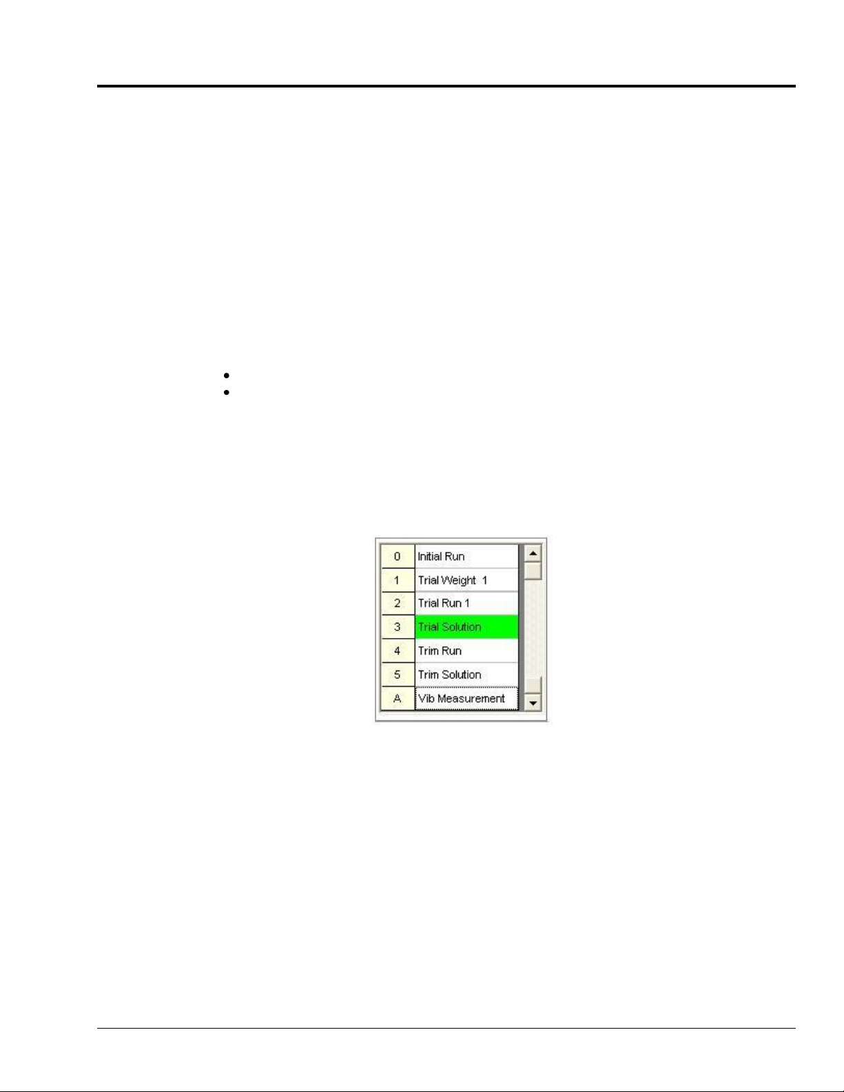
The Balance Operations selection grid identifies where you are in the balance process via a green highlight
for the associated cell; for example “3 Trial Solution” as in the figure. After the trial runs have been
completed a trial balance solution can be determined. After the trim run is performed, you can obtain the
trim balance solution. Chapter 2 contains detailed information.
Balance Operations
Selection Grid
eZ-Balance 978691 Installing and Running the Application 1-3
Page 8

Connecting the Data Acquisition Device
Sensor Type
Single-Ended (SE)
or Differential
Coupling
ICP
Proximity
SE
DC*
OFF
Accelerometer/Velocity
SE
AC
ON or OFF
Depending on the instrument
Tach
SE
AC
OFF
Refer to your hardware documentation in regard to connecting hardware and signal lines; and in regard to
product specifications.
Hardware documents, in PDF format, can be obtained from the following locations:
Directly from the installation CD (select “Manuals” from the CD’s splash screen)
From the online Tech Support section at www.iotech.com
From the Programs group on your CD, providing that you installed your software from a CD
Note that ZonicBook/618E, WaveBook/516 Series, and IOtech 600 Series devices are configured entirely
via software.
In regard to connecting sensors, the following table may prove useful as a general guide.
*Typically, Proximity and DC proportional signals should be DC coupled.
At this point you should be ready to look at the steps required for a balancing project. These are presented
in the next chapter.
1-4 Installing and Running the Application 978691 eZ-Balance
Page 9
A Balancing Project 2
1. Start eZ-Balance …… 2-1
2. Create a New Job …… 2-4
3. Modify the Device Setup for On-line Balancing …… 2-5
Setup Acquisition Tab …… 2-5
Setup Channels Tab …… 2-6
4. Perform Balancing Operations …… 2-11
Initial Balance Run …… 2-5
Add Trial Weight …… 2-8
Trial Balance Run …… 2-9
Calculate Trial Solution …… 2-10
Trim Balance Run …… 2-11
Calculate the Trim Solution …… 2-11
Notes
o Use a standard channel location convention for your Tach and Response channels.
Typically: Tach is channel 1 and Response channels are 2 and above.
o If you aren’t getting a Tach Trigger, verify the Tach channel’s FSV, Trigger Level Percentage, and
Direction.
o If an error should occur, which results in eZ-Balance not booting up, delete the EZBal.ini file
[located in the executable’s directory]. The .ini file identifies the last Job opened. You can delete
this file without affecting your data. After deleting the file you should be able to open the last
balancing job.
1. Start eZ-Balance
To run eZ-Balance, double-click the eZ-Balance icon or use your Windows desktop Start button to navigate
to the program file [or to wherever you installed the program].
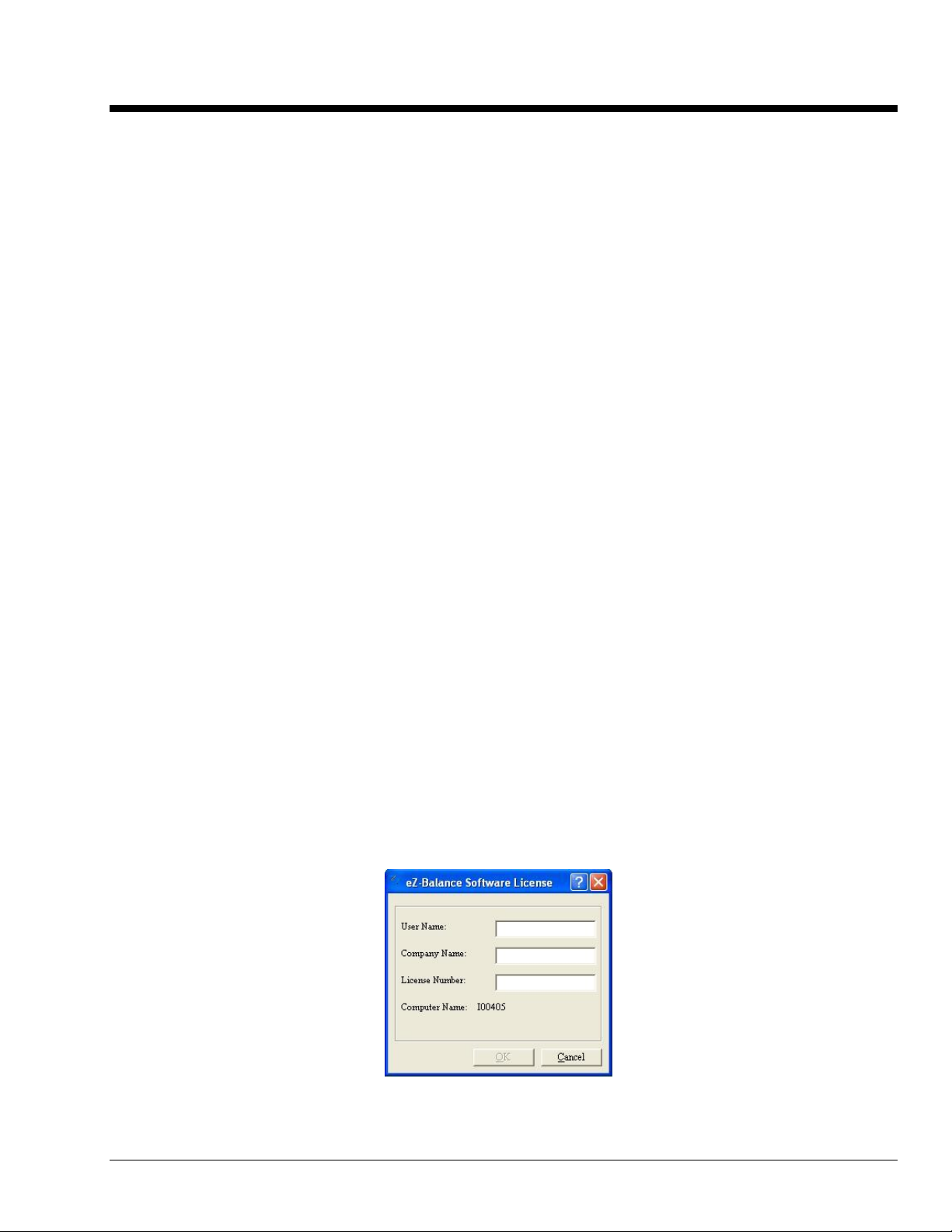
The first time you run eZ-Balance, the Registration Form will open (following figure). You must complete
the registration form in order for eZ-Balance to operate.
The license number accompanies the CD-ROM, or can be provided via e-mail if you downloaded
eZ-Balance from the Web Site. You will not have to re-enter this information again, unless you upgrade to
a newer version, or if you reinstall eZ-Balance.
Should you need to access the form, for example if you received a license for an upgrade, it can be
accessed through the Help pull-down menu. From the available selections, pick “About eZ-Balance...;”
then click the <Update License> button. A screen similar to the following will appear.
License Registration Form
eZ-Balance 987091 A Balancing Project 2-1
Page 10
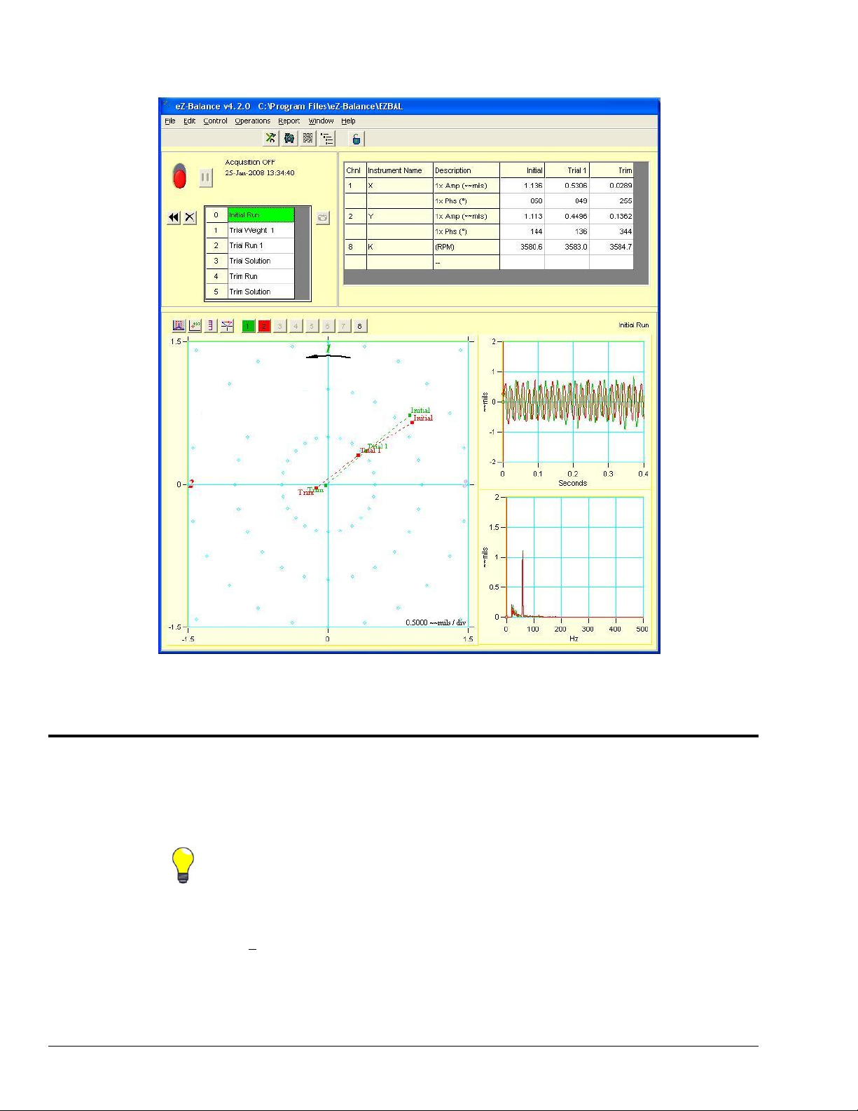
After you complete the form and click <OK>, the eZ-Balance Main window will open. The main window
TIP: We recommend you store all jobs in a separate “Jobs” folder. This allows for
easier file maintenance.
Polar Display
Data Display
Time Display
Spectra Display
provides access to several other windows that you will use interactively throughout the balancing project.
Main Window with its four Displays
2. Create a New Job
2-4 A Balancing Project 987091 eZ-Balance
1. From the File pull-down menu, select “New eZ-Balance File.” This opens the Save As dialog
window.
2. Select or create a folder for your eZ-Balance Project.
3. Enter the name for the eZ-Balance Project.
4. Click the <Save> button to create the new project.
Page 11
You cannot access the Balance Configuration window while Data Acquisition is active.
The control switch must be set to “OFF.”
The number of balance planes can be equal to or less than the number of response
inputs.
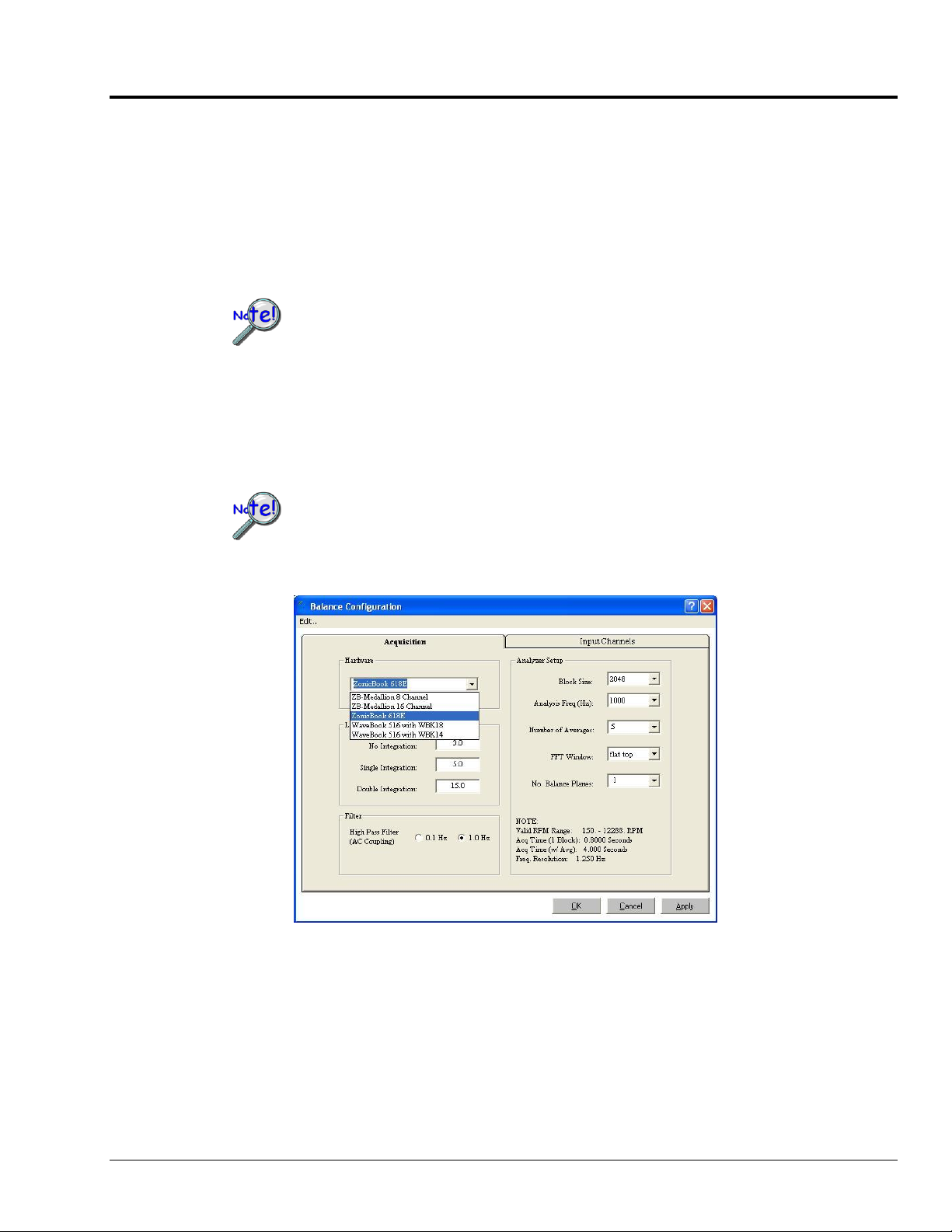
3. Modify the Device Setup for On-line Balancing
After you create a new eZ-Balance job, you need to verify that the default setup is valid for your job.
To modify the Acquisition and Input Channels parameters:
a. With the acquisition turned OFF, open the Edit pull-down menu.
b. Select “Configuration.”
c. From the Acquisition Tab’s Hardware pull-down list, select the applicable data acquisition
hardware.
Setup Acquisition Tab
Use this panel to select the applicable data acquisition hardware and configure the acquisition parameters
for the eZ-Balance Job. If you make any changes, be sure to click the <Okay> or <Apply> button.
Balance Configuration, Acquisition Tab
eZ-Balance 987091 A Balancing Project 2-5
Page 12
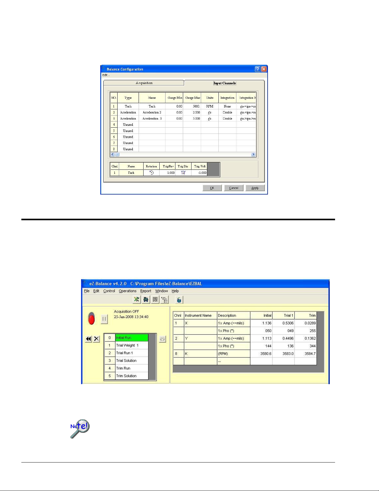
Input Channels Tab
Balance Operations Flowchart
Selecting (0) Initial Balance Run
The number of balance steps depends on the number of balance planes. There will be a
trial run for every balance plane.
Use this panel to configure each channel for your balance job. Select a channel then set the values for each
attribute. Repeat for each channel.
Balance Configuration, Input Channels Tab
4. Perform Balancing Operations
Balance Data can be acquired with the acquisition device on-line, or it can be entered manually (off-line).
Use the Balance Operations flowchart to sequentially select the balance project’s steps. The number of
Balance Steps depends on the number of Balance Planes. There will be a Trial Run for every Balance
Plane.
2-6 A Balancing Project 987091 eZ-Balance
Page 13

Operation: Initial Balance Run
Before acquiring vibration data, verify that your data acquisition device, e.g.,
ZonicBook/618E, WaveBook/516 Series, or IOtech 600 Series device is properly connected
and configured. Refer to your product user manual. IOtech CDs include PDF versions of the
associated documentation.
The first step is to perform an initial balance run. This is the “as found” condition of the machine.
Note: Data in graphics is for presentation purposes only.
On-line Method
Main Display Window
Click the Toggle Switch in the Control Panel to enable the data acquisition. The Vibration Data table
(following figure) displays the measured Speed, 1x Amp, and 1x Phase values. After the machine reaches
a steady state, and data has been collected and averaged, you are ready to proceed to the next step.
Vibration Data Table
eZ-Balance 987091 A Balancing Project 2-7
Page 14

Click on “Trial Weight 1.” This will automatically save the Initial Run data and Pause the acquisition.
Off-line Method
Manually enter the data into the Vibration Data table; then proceed with the next operation,
Add Trial Weight.
Operation: Add Trial Weight
Add Trial Weight
The “Add Trial Weight” operation does the following:
(1) logs the vibration data for the current Run
(2) pauses the acquisition, and
(3) brings up a Trial Weights box
View the plotted vibration data and determine where you may need to add balance weights. Add the
weight to Balance Plane 1. In the Balance Weights window you have a choice of selecting “Any Location”
or “Fixed Locations.” See the following figure.
The “Any Location” setting allows you to enter up to ten trial weight vectors (weight and angle).
The “Fixed Locations” setting is for evenly spaced locations for the trial weights. When this option is
selected enter the number of weight locations and the desired starting angle for the first weight.
eZ-Balance will automatically enter the remaining angles. The default is for 10 locations, starting with
angle °0, and with each location set apart by 36 degrees.
2-8 A Balancing Project 987091 eZ-Balance
Page 15

Operation: Trial Balance Run
Balance Weights Window
Use the same vibration acquisition method to obtain Trial Run Vibration data. Repeat these operations for
each Balance Plane.
Vibration Data Table
eZ-Balance 987091 A Balancing Project 2-9
Page 16

Operation: Calculate the Trial Solution
Calculate Trial Solution
Click the Trial Solution cell.
The Solution area of the Balance Weights window indicates the weight and location to place the final
correction; and includes influence coefficients.
2-10 A Balancing Project 987091 eZ-Balance
Page 17

Operation: Trim Balance Run
Trim Balance Run
Perform a Trim Balance Run to verify the Balance solution.
Operation: Calculate the Trim Solution
Calculate Trim Solution
A Trim Solution provides an updated Balance Solution using the Trim Run results.
Repeat Trim Balance Runs as needed.
1. Calculate a trim solution.
2. Add trim weights.
3. Perform a Trim Balance Run to verify the new balance solution.
4. Repeat the process as desired to fine tune the balance.
If the Balance Solution does not provide desired results, the unsatisfactory vibration levels may be due to
other machine problems, such as misalignment.
eZ-Balance 987091 A Balancing Project 2-11
Page 18

Notes:
2-12 A Balancing Project 987091 eZ-Balance
Page 19

Windows, Buttons, and Menus 3
Polar Display
Data Display
Time Display
Spectra Display
The Main Window …… 3-1
Window Selection Buttons …… 3-2
Control Buttons and Operation Selection Cells …… 3-3
Display Task Bar …… 3-4
Vibration Data Display (Data Display) …… 3-4
Balance Weights Window …… 3- 5
File Menu …… 3-6
Edit Menu ….. 3-6
Control Menu …… 3-12
Operations Menu …… 3-12
Report Menu …… 3-13
Window Menu …… 3-14
The Main Window
The Main window is comprised of menus, buttons, and windows needed to complete a balancing project.
eZ-Balance 969391 Windows, Buttons, and Menus 3-1
Main Window with its four Displays
Page 20

Windows Selection Buttons
Button
Function and/or Comment
Balance
Toolkit
Opens the Balance Toolkit window with its 9 tools for performing various
weight-related calculations. Chapter 4 is devoted solely to the Balance
Toolkit and should be referred to for details.
Machine
Picture
Brings up the Machine Picture window, which allows you to add [or
remove] a .jpg or .bmp picture image via its Edit menu. When the add
function is selected a window appears, allowing you to browse for, and
select, the desired image.
User
Comments
Brings up a window, which allows you to enter text. The window is
typically used to add project notes.
Show
Balance
Projects
Brings up a window, which lists currently saved projects. You can select a
project from the list for post data viewing.
Lock/Unlock
Results Table
A password can be used to lock out editing of the results grid. The state of
this feature may be saved in the eZ-Balance file such that a project can be
configured for locked editing of results and distributed to a testing
environment with manual editing disabled.
You can open the password dialog directly from the Window pull-menu, or
by clicking on the lock icon button [regardless of state].
The “Set Password” entry (in the pull-down menu) is disabled whenever
the state of the interface is „locked,‟ i.e., red icon condition.
Note: The default password used, for example in the case of importing
legacy files, is „ZBAL‟. Passwords are case sensitive.
New projects use the most recent password; and default to the „unlocked‟
state.
The buttons can be used instead of the associated selection in the Windows pull-down menu, which is
discussed on page 3-14.
3-2 Windows, Buttons, and Menus 969391 eZ-Balance
Page 21

Control Buttons and Operation Selection Cells
Button
Comment
Pause/Continue
<Pause/Continue> is used to temporarily halt an acquisition, and to
restart it.
Acquisition On/Off
Turns an acquisition On or Off. Red (down) is “Off.” Green (up) is “On.”
Snapshot
Click the < Snapshot > button to save the current acquisition data to the
History file. The History file is FIFO (first in first out). The number of
records in the file is set in the acquisition tab of the Configuration window.
Erase Vibration Data
- from previous
single run
When this button is clicked the previous single run of vibration data is
instantly erased. There is no warning prompt.
Erase Vibration Data
- from all runs
After clicking this button a message box states: “WARNING - All vibration
data will be erased. Do you wish to continue?” If so, click the <Yes>
button. Otherwise, click <No>.
Alert !
If the input tachometer‟s frequency (number of tach pulses per second) is
greater than the analysis frequency, and not yet attenuated by the input
anti-aliasing filter, then an RPM alert indicator is displayed. The alert icon is
an exclamation point encased in a yellow triangle.
If the input tachometer frequency is attenuated by the input anti-aliasing
filter, then the RPM will be represented as zero and the indicator will not be
displayed.
Pause/
Continue
Acquisition
On/Off
Erase Vibration
Data – All Runs
Erase Vibration
Data – Initial Run
Alert!
Snapshot
Operation
Selection
The Control section of the main window includes a toggle-switch, several buttons, operation selection cells, and a
high RPM “alert” feature. The operations offered by the selection cells (following figure) are discussed in chapter 2,
with exception of selection “A” (Vib Measurement) and the “Alert” feature which is briefly discussed below. The
Vib Measurement operation instructs eZ-Balance to measure vibration data while foregoing the balancing
operation.
eZ-Balance 969391 Windows, Buttons, and Menus 3-3
Page 22

Button
Function and/or Comment
Scale
3 modes
Auto Scale – Automatically sets the scale.
User Scale – Left-click near the high or low ends of the x and/or
y axis to access a numeric field, which allows you to enter new
maximum and minimum values.
Instrument Scale - sets the scale according to the instrument
Data
Annotation
For the chart displays, this button is used to turn annotation (x,y data
values) on or off.
Log Scale
The Log Scale button applies to the Spectrum Display. The button
toggles the scale from Linear to Logarithmic and visa versa.
Apply Runout
This button should be clicked when the machine is running at full speed
so that runout compensation can be applied.
Channels
(8 buttons)
These buttons are used to select (or deselect) the input channel(s).
Display Task Bar
The Plot Display task bar is located at the top edge of the Polar Display panel; but applies to the Time and
Spectra Displays in addition to the Polar Display. The task bar is used to select the active channels to be
displayed and to adjust display parameters in regard to scale, and as to whether or not runout compensation
should be applied. The task bar includes a button for turning the annotation function on or off.
Plot Display Task Bar
Vibration Data Display
Vibration Data Display
The Vibration Data table shows the vibration data for each balance run. The data can be entered manually,
or collected on-line through the data acquisition device.
3-4 Windows, Buttons, and Menus 969391 eZ-Balance
The vibration data is plotted in the Polar, Time, and Spectra displays.
Page 23

TIP: Be aware of your units of weight and be consistent in their use.
The units are not displayed in the Balance Window.
Clears the weights for the current balance plane.
Clears the weights for all balance planes.
Balance Weights Window
Balance Weights Window
This window contains a table for displaying the amount of weight added to specific locations (angles). Angle
selection can be made in either of two ways; (1) “user designated” [via the <Any Location> radio button] and
(2) “automatic” [via the <Fixed Locations> radio button].
Selecting the <Any Location> radio button allows you designate the angles at which the weights will be place.
This option is limited to 10 locations.
Selecting the <Fixed Location> radio button allows you to set the Start Angle and the Number of Locations.
The other locations are automatically set at equal angles, based on the number of locations.
For example, in the preceding figure the specified number of locations is 8. Each of the 8 locations is
45 degrees from the preceding and following locations. When fixed locations are used there must be at least 2;
and not more than 360.
The two buttons at the window’s lower left have the following use.
eZ-Balance 969391 Windows, Buttons, and Menus 3-5
Page 24

File Menu
Edit Menu
The file pull-down menu contains five standard application commands.
New eZ-Balance File - creates a new file for your new balance job.
Open eZ-Balance File - opens an existing file for your balance job.
Save eZ-Balance File - saves project in its current state.
Save As – Opens the “Save As” window allowing you to select an existing file name or create a new one
and choose the location where you want to save the file. For the type of file save you will need to use
eZ-Balance Projects (*.ezb).
Print Screen - opens the Print dialog box.
Exit – closes and exists eZ-Balance.
The Edit menu contains the following selections:
Configuration
Display Preferences
Copy . . . Screen / Polar Plot / Vibration Plots
Edit Menu > Configuration
Selecting Configuration brings up a window with two tabs. Use the Acquisition Tab to configure the
general acquisition parameters. Use the Input Channels Tab to set the tach and input channels. Tab details
follow.
Edit Menu > Configuration Menu > Acquisition Tab
Balance Configuration Acquisition Tab
3-6 Windows, Buttons, and Menus 969391 eZ-Balance
Page 25

Configuration Menu . . . Analyzer Tab
Panel
Function(s)
Hardware
This panel consists of a pull-down list from which you must select your data
acquisition hardware, for example, 600 Series, ZonicBook/618E, or a
WaveBook/516 series device with a WBK14 or WBK18.
Low Frequency
Cutoff Hz
This panel allows you to set values for: No, Single, and Double Integration. Low
frequency cutoff is used to remove the low frequency effects of integration. All
spectral amplitude values below the specified frequency value are set to zero.
Filter
Used to set the High Pass (AC Coupling Filter) to 0.1 Hz or to 1.0 Hz. Note that
coupling is set to AC or DC in the Input Channels tab. Select 1.0 Hz for machines
with RPM > 300.
Analyzer Setup
This panel is located on the right-side of the Balance Configuration tab.
It includes pull-down lists for the following items:
Spectral
Lines
The number of lines per spectrum and the number of data samples used in the FFT
(Fast Fourier Transform) process. The more spectral lines, the greater the data
resolution. As the number of spectral lines increases, so does the time that it takes
to collect the data and the amount of disk space.
Analysis
Frequency
(Hz)
This value is the maximum frequency of interest. The sampling rate will be 2.56
times the analysis frequency. Verify the maximum frequency response of your
probes. Typically, the analysis frequency will be 5x the Machine’s Rotating
Speed.
Number of
Averages
The averaging function is a rolling buffer that averages the last “n” data blocks.
The typical number of averages is 5.
FFT
Window
Options are None, Hanning, Flat Top, or Blackman Harris. Hanning provides
better frequency resolution. Flat Top provides better amplitude resolution.
No. Balance
Planes
eZ-Balance can have between 1 and 7 balance planes, up to the number of response
inputs.
The lower right section of the Analyzer Setup tab includes a note which states:
Valid RPM Range
Acquisition Time (for 1 block)
Acquisition Time (weighted average)
Frequency Resolution
eZ-Balance 969391 Windows, Buttons, and Menus 3-7
Page 26

Edit Menu > Configuration Window > Input Channels Tab
Configuration Window . . . Input Channels Tab
Attribute
Comments
Type
This is the type of instrument that will be connected to the selected channel.
Instrument Types include: Accelerometer, Velocity, X probe, Y probe, Z probe, and
Tach. Make your selection on the pull down menu. If no instrument will be
connected to the channel select “unused.”
You must have 1 Tach Channel and 1 or more Response Channels.
For IOtech 650 units, CH5 should never be configured as an accelerometer channel
since it has no IEPE capability.
Name
Enter a name, or label, for the selected channel.
Gauge Min
Gauge Max
Enter the instrument Range: Minimum and Maximum in engineering units.
Units
Default engineering units are based on the Instrument Type selected. To change the
units, double-click on the cell and type in the desired unit label.
In regard to selecting an IOtech 650 unit channel Type [preceding table], channel 5
should never be configured for accelerometer input. This is because channel 5 has
no IEPE capability.
The Balance Configuration window includes an Input Channels tab (following figure). Use this tab to
configure each input signal. Set the values for each attribute on a channel by channel basis. Note that the
following figure does not show all attributes. To view additional attributes you would use the scroll bar
[below channel 8] and scroll to the right. A table of channel attributes follows.
Balance Configuration Input Channels Tab
3-8 Windows, Buttons, and Menus 969391 eZ-Balance
Page 27

Configuration Window . . . Input Channels Tab
Attribute
Comments
Integration
None
Single
Double
Accelerometer and velocity signals can be integrated. Select the desired integration type
[None, Single, or Double]. To do this, left-click on the cell and select the integration
type from the resulting list.
In regard to integrating acceleration and velocity:
. . . for Acceleration: single integration results in velocity.
double integration results in displacement.
. . . for Velocity: single integration results in displacement.
FSV
(Full Scale
Voltage)
Select the maximum Full Scale Voltage that is expected for the instrument.
Erroneous results will occur if you select a voltage value that is less than the actual input
voltage. If you are unsure of the instrument’s maximum voltage value, select a high
voltage value [i.e.: +/-25V for displacement probes; +/- 5V for accelerometers and
velocity sensors.]
IEPE
(Integral
Electronics
Piezoelectric)
The Institute of Environmental Science and Technology adopted the term IEPE (Integral
Electronics Piezoelectric) to identify what had been commonly referred to as ICP®
(Integrated Circuit Piezoelectric). The two terms are synonymous; however, ICP is
registered by PCB Pizeotronics.
A constant bias current is available for IEPE transducers that are used as signal input for
associated analog channels and for compatible expansion modules that accept IEPE
transducers, for example, the WBK18. The bias current is sourced through the center
conductor of the input channel BNC connector and returns to the acquisition device [e.g.,
ZonicBook/618E or the WBK18, or IOtech 600 Series device] via the BNC’s outer
conductor.
The current source features an operating compliance voltage (see specs) and is protected
in regard to both short-circuit and overvoltage. Operating compliance refers to the
highest voltage that can be applied without change of the current source value. For
applications that do not require bias, the current source can be disconnected from the
input by un-checking IEPE in the Input Channels tab on a per-channel basis.
Checking a channel’s IEPE cell enables the current source for that channel. With IEPE
enabled, level detection circuitry continuously monitors the channel’s input voltage.
Recognition of a voltage greater than 25V (transducer open) or less than 1V (transducer
short) triggers a transducer fault condition for the associated channel. This error is
communicated to the user via a front panel LED on some units (not on 600 Series) and is
also available through a software status request at the end of an acquisition. When
recognized, an error is latched until the commencement of a new acquisition.
Consequently, even intermittent faults are detected and communicated. Detection of a
fault does not, however, alter the acquisition process or its data.
When the IEPE function is not available to a channel a dash appears in the IEPE column
for the associated channel.
eZ-Balance 969391 Windows, Buttons, and Menus 3-9
Page 28

Configuration Window . . . Input Channels Tab
Attribute
Comments
Coupling
AC or DC coupling can be set on an individual channel basis. Coupling is available for
analog channels (CH1 through CH8) and for compatible expansion channels [e.g., from a
WBK18]. AC Coupling can be set to a high pass filter value of 0.1 Hz or 1 Hz. The
value is selected in the Analyzer Tab. Note that when DC Coupling is selected the high
pass filter is bypassed.
When the Coupling function is not available to a channel, or not used by a channel, a
dash appears in that channel’s Coupling column.
mV/EU
This is the instrument’s input Sensitivity. Typical accelerometers have a sensitivity of
100 mV per g. Displacement probes have 200 mV per mil.
For Tach probes enter 1000 mV per Volt.
Angle
Angle refers to the physical angular location of a probe. Zero degrees is defined to be
TDC (+y-axis). The angle value is measured in the counterclockwise (CCW) direction.
Typically viewed from the driver end. Instrument angle is used for data display.
1xA Ref
1xP Ref
The 1x (first order) Amplitude and Phase values are used for
Runout Compensation on Bode or Polar displays. These values are commonly known as
Slow Roll Compensation values and should be collected during machine slow roll
conditions (i.e.: Speeds < 500 rpm). The values must be between the Maximum and
Minimum EU range.
3-10 Windows, Buttons, and Menus 969391 eZ-Balance
Page 29

For Tach Probes, you will need to enter the following information. The tachometer related information is
entered at the lower section of the input channels tab (see previous figure).
Rotation
Select the machine’s Rotation Direction, either CCW (counter-clockwise) or
CW (clockwise) on the pull down menu. The rotation direction is typically viewed from
the driver end. Rotation direction is used for data display correction.
Trig/Rev
Enter the number of tach trigger pulses per shaft revolution. This number must be 1 for
all Balance Jobs. Phase can not be calculated if the number of trigger pulses is greater
than 1.
Trig Dir
Select the tach’s trigger pulse direction, either Negative or Positive. Typically this is the
direction of the tach signal’s leading edge. Trigger voltage and direction define the start
of a shaft rotation. A keyway will generate a Negative Tach pulse.
Trig Volt
The tach’s Trigger Voltage number must be less than the tach’s FSV. A tach pulse is
recognized when the tach signal exceeds the trigger voltage in the trigger direction
specified. Trigger voltage and direction define the start of a shaft rotation. Typical Tach
signals will generate at least a 1 V pulse.
Set Defaults
Sets instrument’s attributes to the default values, based on the defined instrument type.
Copy
Channel
Copies the channel attributes of the channel where the cursor is currently residing.
Paste
Channel
Pastes the copied channel attributes to the channel where the cursor is currently
residing.
Fill Down
Copies the channel attributes of the channel where the cursor is currently residing and
copies them to all succeeding channels that are not marked “unused.”
Fill Up
Copies the channel attributes of the channel where the cursor is currently residing and
copies them to all preceding channels that are not marked “unused.”
Notes:
o Use a standard channel location convention for your Tach and Response channels.
Typically: Tach is channel 1 and Response channels are 2 through 8.
o If you aren’t getting a Tach Trigger, verify the Tach channel’s FSV and Trigger
Level Percentage and Direction.
Edit Menu >Configuration Window>Input Channel Tab > Edit
This pull-down menu is located at the upper left side of the Balance Configuration Window. It can only be
opened when the Input Channels tab is active. Menu items are as follows:
eZ-Balance 969391 Windows, Buttons, and Menus 3-11
Page 30

Edit Menu > Display Preferences
From the Display Preferences window you can set plot related
colors, e.g., frame color, border color, grids, etc. It is from this
window that channel trace colors are set.
In addition to the parameters just discussed, you can:
Use the Machine Information panel to identify the
machine by name.
Use the Frequency Axis panel to label the
frequency (x-axis) in Hz or CPM.
Use the Report Format panel to choose NotePad or
MS Word as the format for the Balance
Configuration Report, which is selected from the
Report pull-down menu. You can paste the report
into other documents.
After making changes to the display preferences, remember to
hit the <OK> or <Apply> button. Otherwise the changes will
not take effect.
Edit Menu > Copy . . . Screen / Plot Window / Vibration Data
There are three individual copy options: Copy Screen, Copy Plot Window, and Copy Vibration Data. Each
is a command to copy the specified screen image. After copying the image you can paste it into a text
document such as MS Word or a graphics application, such as MS Paint.
Control Menu
With exception of its “Save Balance Operation Data” function, the Control pull-down menu mimics the
functionality of the Control section of the Main Window. The menu allows you to start and stop
acquisitions, pause and continue acquisitions, and to save data.
Operations Menu
This menu has the same options as does the Main Window’s Balance Operation selection grid; i.e.,
Initial Run, Trial Weight, Trial Run, etc. Refer to chapter 2 for a description of the operation levels.
3-12 Windows, Buttons, and Menus 969391 eZ-Balance
Page 31

Report Menu
This menu allows you to generate a report in regard to Balance Solution [if present] and/or Balance
Configuration. A report can be set for one of three formats: NotePad, MS Word, or MS Excel. The default
is NotePad. The format is changed from Display Preferences [under the Edit pull-down menu].
The following is a portion of a report that was generated in the MS Word format, then pasted into this
document. Note that the report can be edited, just any other text in a Word document.
ACQUISITION CONFIGURATION
Hardware Device: WaveBook 516 with WBK14
Analysis Rate: 1000 Hz
Blocksize: 2048
Averages: 5
Cutoff -No Int: 3 Hz
Cutoff -Single Int: 5 Hz
Cutoff -Double Int: 15 Hz
FFT Window: Flat Top
Picture File:
CHANNELS CONFIGURATION
Channel 1: Tach
Name: Tach
Range: 0.00 - 5000. RPM
FSV: 20.00
mV/EU: 1000.
Angle: 0
Rotation Direction: CCW
Trigger Voltage: -1.000
Trigger Direction: NEG (-)
Partial Balance Configuration Report
eZ-Balance 969391 Windows, Buttons, and Menus 3-13
Page 32

Window Menu
Window
Menu
Selection
Function and/or Comment
Associated
Panel
Button
Balance
Toolkit
Opens the Balance Toolkit window which has tools for performing
various weight-related calculations.
Note that chapter 4 is devoted solely to the Balance Toolkit and
should be referred to for details.
Machine
Graphic
Brings up the Machine Picture window, which allows you to add [or
remove] a .jpg or .bmp picture image via its Edit menu. When the
add function is selected a window appears, allowing you to browse
for, and select, the desired image.
User
Comments
Brings up a window which allows you to enter text. The window is
typically used to add project notes.
Set
Password
A password can be used to lock out editing of the results grid. The
state of this feature may be saved in the eZ-Balance file such that
a project can be configured for locked editing of results and
distributed to a testing environment with manual editing disabled.
You can open the password dialog directly from the Window pullmenu, or by clicking on the lock icon button [regardless of state].
The “Set Password” entry (in the pull-down menu) is disabled
whenever the state of the interface is „locked,‟ i.e., red icon
condition.
Note: The default password used, for example in the case of
importing legacy files, is „ZBAL‟. Passwords are case sensitive.
New projects use the most recent password; and default to the
„unlocked‟ state.
Unlocked
Locked
eZ-Balance
Projects
Brings up a window with a list currently saved projects. You can
select a project from the list for post data viewing.
The Windows pull-down menu is directly related to the Windows panel.
3-14 Windows, Buttons, and Menus 969391 eZ-Balance
Page 33

Balance Toolkit 4
If the rotor is near resonance, a force equal to 10% of the rotor will have too large of an
effect. If there is past sensitivity data available, it should be used.
Trial Weight …… 4-1
Split Weights …… 4-2
Resolving Weights …… 4-3
Chord-Angle-Arc …… 4-3
Runout Compensation …… 4-4
Unbalance Tolerance …… 4-5
Stock Weights …… 4-6
Drill Bit Weights …… 4-7
Arc Weight …… 4-8
The Balance Toolkit provides the means to quickly make a variety of useful balance calculations. To open
the toolkit window, select “Balance Toolkit” from the main screen’s Window pull-down menu or press the
< Balance Toolkit > button. It is the first button in the Window panel.
There are 9 tabs in the Balance Toolkit window (see following figure). Each tab accesses a specific
balance calculation. Clicking on an inactive tab brings it to the foreground.
Two panels and a button reside to the left of the tabs. The upper panel is for identifying engineering units
as English or Metric. The second panel is for selecting the type of material, e.g., steel, aluminum, etc. The
<Calculate Value> button executes the calculation, instantly solving for an unknown variable, or, in some
instances, generates a message [likely due to an invalid data entry].
Trial Weight
The Trial Weight tab is used to calculate the weight needed to generate a force equal to 10% of the rotor
weight. The Trial Weight can be calculated by entering the rotor radius, rotor weight, speed in RPM; and
then clicking the <Calculate Value> button.
You can also use this tab to calculate Centrifugal Force by entering the radius, rotor speed, the trial weight;
and then clicking the <Calculate Value> button.
Trial Weight Tab
eZ-Balance 939093 Balance Toolkit 4-1
Page 34

Split Weights
Find Split Weights. There are times when additional weight is needed at a specific angular location. On
some of these occasions there is no adequate mounting location. The Split Weights tab is used to calculate
the amount of weight that can be attached at locations other than the one originally intended. The solution
weights for the given angles will have the same effect as the original amount of weight.
Split Weights Tab – Spread Angle Selected
To calculate split weights: Enter (1) the amount of weight to be added, (2) the angle closest to the original
angular position required by your calculations, and (3) the spread angle; (4) click the <Calculate Value>
button. The tab will display the two solution weights (W1 and W2).
Split Weights Tab – Even Weights (W1 = W2) Selected
Find Angles for Even Split Weight Values. This use of this function requires that the additional weights
will be identical (W1 = W2). The two solution angles for the given weight will be calculated.
To calculate the angles: Enter (1) the “effective weight”, (2) the “Effective Angle” according to the position
required by your calculations, and (3) the value of a single “Balanced Weight.” Note that W1 + W2 must
not be greater than the Effective Weight; (4) click the <Calculate Value> button. The tab will display the
two solution angles (Wt.1 Angle and Wt.2 Angle).
4-2 Balance Toolkit 939093 eZ-Balance
Page 35

Resolving Weights
This tab is used to calculate the effect of placing multiple weights at multiple locations. To obtain
the overall effective weight and angle: enter the weight and angular position (in degrees) for each
balancing weight; then click the <Calculate Value> button.
Resolving Weights Tab
Chord-Angle-Arc
Chord-Angle-Arc Tab
This tab is used to calculate the Chord, Angle, or Arc when the radius and one of three other variables is
known.
To make a calculation: (1) enter the radius, (2) click the radio button for the known variable, and then
(3) enter the value of the variable. For example, in the preceding figure the angle was known to be 30°.
(4) Click the <Calculate Value> button. The tab will display the values of the two remaining variables in
the lower center of the screen.
eZ-Balance 939093 Balance Toolkit 4-3
Page 36

Runout must be compensated for prior to balancing.
Runout Compensation
Runout Compensation Tab
The Runout Compensation Tab is used to find compensated amplitude and phase. The tab uses vector
subtraction; and subtracts the runout measured at low speed from the runout measured at balancing speed.
This calculation can also be used to determine the actual amount of vibration that is present in the system.
To make the calculation simply enter the amplitude and phase for balancing speed (V1) and then enter the
values for slow roll (V2). Compensated amplitude and phase (V3) are calculated after each data entry.
V1 - V2 = V3
V1 equals the uncompensated amplitude and phase for balancing speed.
V2 equals the amplitude and phase for slow roll.
V3 equals the compensated amplitude and phase.
4-4 Balance Toolkit 939093 eZ-Balance
Page 37

Grade Values and Associated Uses
ISO
Balance
Grade No.
Typically used for the following applications.
40.0
Car wheels and rims.
16.0
Auto drive shafts, crushing and agricultural equipment.
6.3
Process rotors, centrifuges, fans, flywheels, and pumps.
2.5
Turbines, blowers, machine tools, large and medium motors.
1.0
Jet engines, recorder drives, and grinding machines.
0.4
Armatures and shafts of precision grinding machines.
Unbalance Tolerance
Unbalance Tolerance Tab
This tab is used to calculate the acceptable amount [the tolerance] of residual unbalance.
The first step in making the calculation is to select the Balance Grade from the pull-down list.
The ISO balance grade standards are presented in the flowing table.
When a balance grade is selected, the tab displays a list of equipment normally associated with
that grade. This is indicated in both the preceding figure and table.
After entering the ISO Balance Grade, enter rotor weight and speed. The Upper Limit for Rigid
Frames and the Lower Limit for Flexible Frames will be displayed at the bottom of the window
whenever a value [Balance Grade, Rotor Speed, or Rotor Weight] is entered.
eZ-Balance 939093 Balance Toolkit 4-5
Page 38

Stock Weights
Stock Weights Tab
This tab is used to calculate stock weight, or the length of stock, depending on which variables are known.
For flat stock: Select the radio button labeled “Flat;” then solve for weight or height.
To find weight enter the length, width, and height of the specified stock.
To find length enter the height, width, and weight of the specified stock.
For round stock: Select the radio button labeled “Round;” then solve for weight or height. Note that the
tab will change appropriately when solving for round stock, i.e., the graphic will change from a block
image to that of a bar, and the height and width fields will be replaced by a single field for diameter.
To find weight enter the diameter and the length the specified stock.
To find length enter diameter and the weight of the specified stock.
4-6 Balance Toolkit 939093 eZ-Balance
Page 39

Drill Bit Weights
Drill Bit Weights Tab
This tab is used to calculate the drilling depth needed to remove a specified weight of material. It can also
be used to calculate the weight that will be removed by drilling to a specified depth.
To calculate drill depth: For the chosen material, such as steel, aluminum, iron, etc.: enter the diameter of
the drill bit and the desired amount of weight to be removed. Hit the <Calculate Value> key. The Drill
Depth will be displayed.
To calculate weight: For the chosen material, such as steel, aluminum, iron, etc.: enter the diameter of the
drill bit and the depth that is to be [or was] drilled. Hit the <Calculate Value> key. The weight will be
displayed.
eZ-Balance 939093 Balance Toolkit 4-7
Page 40

Arc Weight
This tab can be used to calculate the effect of weight added over an arc. It can also be used to calculate
the weight needed to cause a desired effect.
Arc Weight Tab
To calculate the effect of weight to be added over an arc: Enter the arc length, weight to be added,
added, and the radius. Hit the <Calculate Value> key. Effective Weight and Degrees of Arc will be
displayed.
To calculate the weight needed to cause a desired effect: Enter the weight/length (arc length divided by
arc weight), the weight added, and the radius. Hit the <Calculate Value> key. The Arc length, Arc Weight,
and Degrees of Arc will be displayed.
4-8 Balance Toolkit 939093 eZ-Balance
 Loading...