

Page 1

E-1608
Document Revision 1
December 2014
© Copyright 2014
User's Guide
Ethernet-based High-speed Multifunction DAQ
Page 2

HM E-1608.docx
Your new Measurement Computing product comes with a fantastic extra —
Management committed to your satisfaction!
Thank you for choosing a Measurement Computing product—and congratulations! You own the finest, and you can now enjoy
the protection of the most comprehensive warranties and unmatched phone tech support. It’s the embodiment of our mission:
To provide data acquisition hardware and software that will save time and save money.
Simple installations minimize the time between setting up your system and actually making measurements. We offer quick and
simple access to outstanding live FREE technical support to help integrate MCC products into a DAQ system.
Limited Lifetime Warranty: Most MCC products are covered by a limited lifetime warranty against defects in materials or
workmanship for the life of the product, to the original purchaser, unless otherwise noted. Any products found to be defective in
material or workmanship will be repaired, replaced with same or similar device, or refunded at MCC’s discretion. For specific
information, please refer to the terms and conditions of sale.
Harsh Environment Program: Any Measurement Computing product that is damaged due to misuse, or any reason, may be
eligible for replacement with the same or similar device for 50% of the current list price. I/O boards face some harsh
environments, some harsher than the boards are designed to withstand. Contact MCC to determine your product’s eligibility for
this program.
30 Day Money-Back Guarantee: Any Measurement Computing Corporation product may be returned within 30 days of
purchase for a full refund of the price paid for the product being returned. If you are not satisfied, or chose the wrong product by
mistake, you do not have to keep it.
These warranties are in lieu of all other warranties, expressed or implied, including any implied warranty of merchantability or
fitness for a particular application. The remedies provided herein are the buyer’s sole and exclusive remedies. Neither
Measurement Computing Corporation, nor its employees shall be liable for any direct or indirect, special, incidental or
consequential damage arising from the use of its products, even if Measurement Computing Corporation has been notified in
advance of the possibility of such damages.
Trademark and Copyright Information
Measurement Computing Corporation, InstaCal, Universal Library, and the Measurement Computing logo are either trademarks
or registered trademarks of Measurement Computing Corporation. Refer to the Copyrights & Trademarks section on
mccdaq.com/legal for more information about Measurement Computing trademarks. Other product and company names
mentioned herein are trademarks or trade names of their respective companies.
© 2014 Measurement Computing Corporation. All rights reserved. No part of this publication may be reproduced, stored in a
retrieval system, or transmitted, in any form by any means, electronic, mechanical, by photocopying, recording, or otherwise
without the prior written permission of Measurement Computing Corporation.
Notice
Measurement Computing Corporation does not authorize any Measurement Computing Corporation product for use
in life support systems and/or devices without prior written consent from Measurement Computing Corporation.
Life support devices/systems are devices or systems that, a) are intended for surgical implantation into the body, or
b) support or sustain life and whose failure to perform can be reasonably expected to result in injury. Measurement
Computing Corporation products are not designed with the components required, and are not subject to the testing
required to ensure a level of reliability suitable for the treatment and diagnosis of people.
Page 3

Table of Contents
Preface
About this User's Guide ....................................................................................................................... 5
What you will learn from this user's guide ......................................................................................................... 5
Conventions in this user's guide ......................................................................................................................... 5
Where to find more information ......................................................................................................................... 5
Chapter 1
Introducing the E-1608 ......................................................................................................................... 6
Ethernet interface ................................................................................................................................................ 6
Functional block diagram ................................................................................................................................... 7
Chapter 2
Installing the E-1608 ............................................................................................................................. 8
Unpacking........................................................................................................................................................... 8
Installing the software ........................................................................................................................................ 8
Connecting the external power adapter .............................................................................................................. 8
Connecting the E-1608 ....................................................................................................................................... 8
Configuring network settings ............................................................................................................................. 9
Address mode settings ...................................................................................................................................................... 9
IP address settings ............................................................................................................................................................. 9
Setting up the E-1608 for communication across networks................................................................................ 9
Configuring network alarms ............................................................................................................................. 10
Restoring factory default network settings ....................................................................................................... 10
Calibrating the hardware................................................................................................................................... 10
Updating firmware ................................................................................................................................ ............ 10
Chapter 3
Functional Details ............................................................................................................................... 11
Analog input modes .......................................................................................................................................... 11
Software paced .................................................................................................................................................................11
Hardware paced ...............................................................................................................................................................11
Device components........................................................................................................................................... 11
Ethernet connector ...........................................................................................................................................................11
External power connector ................................................................................................................................................12
LEDs ................................................................................................................................................................................12
Factory reset button .........................................................................................................................................................12
Screw terminals................................................................................................................................................................12
Signal connections ............................................................................................................................................ 13
Analog input ....................................................................................................................................................................13
Analog output ..................................................................................................................................................................15
External clock I/O ............................................................................................................................................................15
Digital I/O ........................................................................................................................................................................15
Trigger input ....................................................................................................................................................................16
Counter input ...................................................................................................................................................................16
Power output ....................................................................................................................................................................16
Ground ................................................................................................................................................................ .............16
Mechanical drawings ................................................................................................................................ ........ 17
Chapter 4
Specifications ...................................................................................................................................... 20
Analog input ..................................................................................................................................................... 20
Accuracy ........................................................................................................................................................... 21
Analog input DC voltage measurement accuracy ............................................................................................................21
Noise performance ...........................................................................................................................................................21
3
Page 4

E-1608 User's Guide
Settling time .....................................................................................................................................................................21
Analog output ................................................................................................................................................... 21
Analog input/output calibration ........................................................................................................................ 22
Digital input/output........................................................................................................................................... 22
External trigger ................................................................................................................................ ................. 23
External clock input/output............................................................................................................................... 23
Counter ............................................................................................................................................................. 24
Memory ............................................................................................................................................................ 24
Power ................................................................................................................................................................ 25
Network ............................................................................................................................................................ 25
Ethernet connection .........................................................................................................................................................25
Network interface ............................................................................................................................................................25
Network factory default settings ......................................................................................................................................26
Network security ..............................................................................................................................................................26
LED displays and the factory reset button ........................................................................................................ 26
Environmental .................................................................................................................................................. 26
Mechanical ....................................................................................................................................................... 26
Screw terminal connector ................................................................................................................................. 27
Declaration of Conformity .................................................................................................................. 28
4
Page 5

About this User's Guide
What you will learn from this user's guide
This user's guide describes the Measurement Computing E-1608 data acquisition device and lists device
specifications.
Conventions in this user's guide
For more information about …
Text presented in a box signifies additional information and helpful hints related to the subject matter you are
reading.
Caution! Shaded caution statements present information to help you avoid injuring yourself and others,
damaging your hardware, or losing your data.
bold text Bold text is used for the names of objects on a screen, such as buttons, text boxes, and check boxes.
italic text Italic text is used for the names of manuals and help topic titles, and to emphasize a word or phrase.
Preface
Where to find more information
Additional information about E-1608 hardware is available on our website at www.mccdaq.com. You can also
contact Measurement Computing Corporation by phone, fax, or email with specific questions.
Knowledgebase: kb.mccdaq.com
Tech support form: www.mccdaq.com/support/support_form.aspx
Email: techsupport@mccdaq.com
Phone: 508-946-5100 and follow the instructions for reaching Tech Support
5
Page 6

Chapter 1
Introducing the E-1608
The E-1608 is compatible with both TCP/IP (IPv4 only) and user datagram protocol (UDP) network protocols.
The E-1608 provides the following features:
Four differential (DIFF) or eight single-ended (SE) analog input channels (16-bit)
Sample rates up to 250 kS/s aggregate
Two analog output channels (16-bit)
Eight individually configurable digital I/O channels
One counter channel (32-bit) that counts TTL pulses
Screw terminals for field wiring connections
The E-1608 is powered by a 5 volt power adapter.
Ethernet interface
The E-1608 has one built-in 10/100 BASE-T auto-negotiation, high-speed communication port.
With the Ethernet interface, you can remotely access and configure your E-1608 from anywhere on the network.
Only one computer can control the E-1608 at one time. The networking protocols are TCP/IP and UDP.
A unique media access control (MAC) address is assigned to each device at the factory.
You configure the Ethernet connection settings through software. A network name in the format E-1608-
xxxxxx, is assigned to the E-1608, where xxxxxx represents the lower six characters of the device MAC
address.
6
Page 7

E-1608 User's Guide Introducing the E-1608
Functional block diagram
E-1608 functions are illustrated in the block diagram shown here.
Figure 1. Functional block diagram
7
Page 8

Chapter 2
Installing the E-1608
Unpacking
As with any electronic device, you should take care while handling to avoid damage from static
electricity. Before removing the device from its packaging, ground yourself using a wrist strap or by simply
touching the computer chassis or other grounded object to eliminate any stored static charge.
Contact us immediately if any components are missing or damaged.
Installing the software
Refer to the MCC DAQ Quick Start for instructions on installing the software on the MCC DAQ CD. Refer to
the device product page on the Measurement Computing website for information about the included and
optional software supported by the E-1608.
Install the software before you install your device
The driver needed to run the E-1608 is installed with the software. Therefore, you need to install the software
package you plan to use before you install the hardware.
Connecting the external power adapter
Power to the E-1608 is provided with the 5 V external power adapter (PS-5V1AEPS). Connect the adapter cord
to the power connector on the E-1608 device, and plug the AC adapter into an electrical outlet.
The Power LED turns on when 5 V power is supplied to the E-1608. If the voltage supply is less than 3.3 V or
more than 5.9 V, the POWER LED does not turn on.
Refer to Figure 2 on page 11 for the location of the Power LED.
Connecting the E-1608
The E-1608 requires a TCP/IP and UDP connection to a network or computer. Use the standard Ethernet cable
provided to connect the E-1608 to a 10Base-T- or 100Base-TX compatible Ethernet port, hub, or switch.
When connecting the E-1608 for the first time, make sure that you connect to a local network with DHCP
enabled.
If you are unsure whether you have access to a local network or that DHCP is enabled on that network, you
should use a direct connection to a Windows PC.
It may take a minute or two to detect the device and assign the address. The green Link/activity LED on the
lower left of the Ethernet connector turns on when there is a valid Ethernet link, and blinks when network
activity is detected.
Once the E-1608 is physically connected to the local network or PC, you can run the software (InstaCal for
example) to establish a connection. If a connection cannot be established, make sure the device is using the
default configuration by following the instructions in the Restoring factory default network settings on page 10.
Once a connection is established and you can communicate to the device, you can change the configuration for
other network scenarios.
8
Page 9

E-1608 User's Guide Installing the E-1608
Configuring network settings
The following E-1608 network settings are software-selectable. Only one user at a time can connect to the E1608 to configure network options on the device. For typical local networks, the default settings are
recommended.
Address mode settings
The address mode setting determines whether the default IP parameters (IPv4 address, subnet mask, and
gateway) are assigned to the E-1608 or an auto-addressing method is used to assign these parameters.
DHCP or link-local enabled (default)
If connected to a network with a DHCP server, the service automatically assigns IP addresses to the E-1608.
If the connected network does not have a DHCP server, the address stored in the default IP address is assigned
to the E-1608.
If the E-1608 is directly connected to a Windows PC, a link-local address is assigned to the device. A link-local
address is valid only for communications between the E-1608 and the PC to which it is connected
DHCP Only
Enables configuration by a DHCP server if one is available. The E-1608 is assigned an IP address shortly after
it is powered up and attached to the network.
Link Local Only
The E-1608 is assigned a link-local IP address by the Windows PC to which it is connected. A link-local
address is valid only for communications between the E-1608 and the PC to which it is connected.
Static
The default IPv4 Address is manually configured on the E-1608 .
IP address settings
The default settings of the following IP address are assigned to the E-1608 when automatic addressing is
disabled or not available (DHCP or Link Local for example)
IPv4 address – The IP address that is stored on the device. The default IPv4 address is 192.168.0.101.
Subnet mask – The Subnet mask that is stored on the E-1608 . The subnet mask determines the number of
bits of the IP address that is used for the host portion of the address vs. the number of bits used for the
network portion. The default subnet mask is 255.255.255.000
Gateway – The gateway IP address that is stored on the E-1608. The gateway address of the device that
bridges subnets within a network. The default gateway is 192.168.0.1
Connection code
A number between 0 (default) and 999999999. Change this number from its default of 0 to prevent other users
from connecting to and configuring the device. The device remains visible to other users on the network, but
connection by another user is not allowed.
Setting up the E-1608 for communication across networks
In order to communicate with the E-1608 from a computer connected to a different network – such as over the
Internet – you must change the network configuration of the network router.
In the following procedure, the E-1608 is installed on the host LAN, and the computer is installed on the client
LAN.
Caution! This procedure should only be performed by a network administrator or computer professional.
Incorrect settings can significantly disrupt a network.
9
Page 10

E-1608 User's Guide Installing the E-1608
1. Assuming you have successfully connected to a local network, determine the IP address of the device. If
the address was assigned by DHCP, it is recommended you change it to a static address by setting the
default address to the address assigned and setting the device network configuration to static.
2. Configure the firewall/router to forward incoming traffic to the following ports to the IP address assigned
to the device:
o UDP:54211 (discovery)
o TCP:54211 (commands)
o TCP:54212 (scan data)
3. On the computer connected to the client LAN, manually enter the WAN address of the host router, and
specify the ports that were forwarded to connect to the remote E-1608.
If the ports listed above are not available on your router, you can use the following guidelines to select different
ports: The first port must be configured for both UDP and TCP. The second port must be adjacent to the first
and configured for TCP. For example, you could use 54221 (TCP and UDP) and 54222 (TCP).
Configuring network alarms
You can use software to configure any digital output bit and/or each analog output channel to generate specific
values to indicate when the device is connected and/or disconnected.
The settings can also be used to initialize an output to a specific value when the device connects or disconnects
from the network.
Restoring factory default network settings
To reset the network configuration settings to the factory default values, complete the following steps (refer to
Device components on page 11 for the location of this button):
1. Remove power from the device.
2. Press and hold the Factory reset button while re-applying power.
3. Hold the button for at least four seconds until both the Power and Activity LEDs blink , indicating that the settings
have been restored to the factory defaults.
4. Release the button so the device continues startup with the default settings. If the button is released before the two
LEDs blink, the settings are not affected and the device starts up normally.
If InstaCal is open when default settings are restored, click the Refresh Boards button on the InstaCal toolbar
to reflect the changes.
Calibrating the hardware
The Measurement Computing Manufacturing Test department performs the initial factory calibration. Contact
Measurement Computing for details about how to return your device and have it calibrated to the factory
specifications. The recommended calibration interval is one year.
Field calibration is not supported.
Updating firmware
Your DAQ device contains firmware that can be updated in the field if required. Firmware is available for
download at www.mccdaq.com/firmware.aspx. MCC recommends that you check this page periodically to see
if an update to your device firmware is available.
10
Page 11
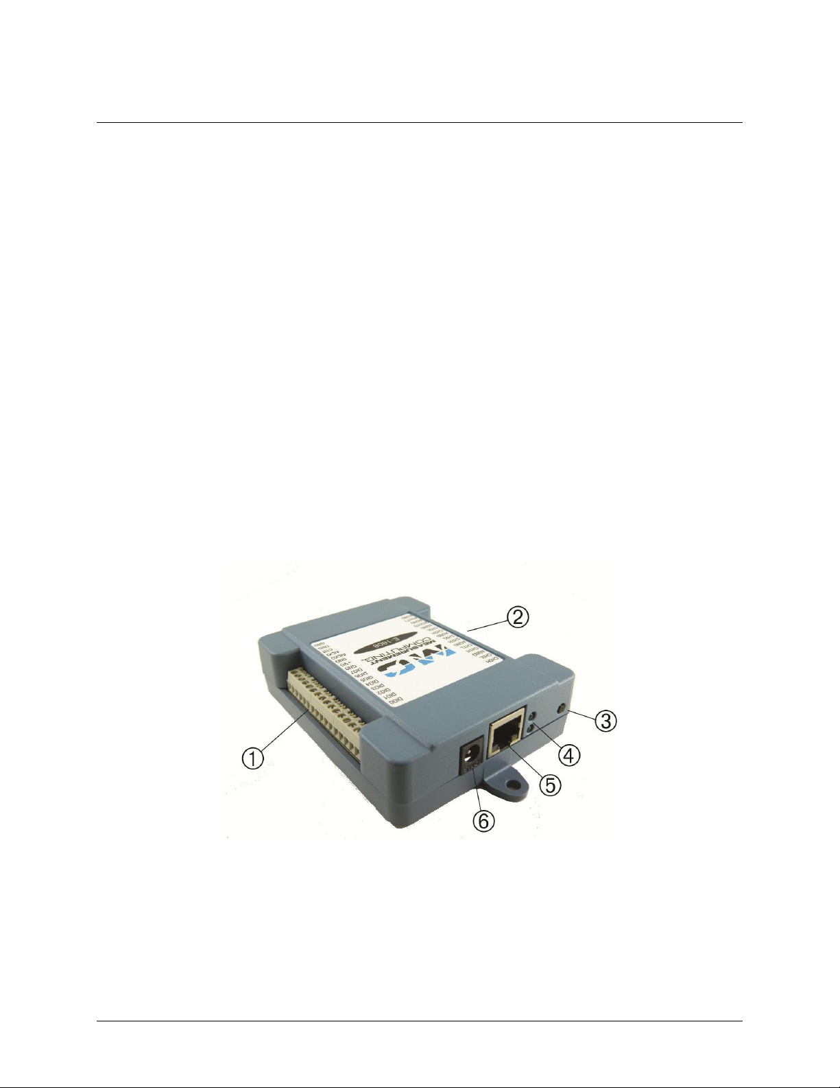
1
Screw terminal pins 17 to 32
4
Power LED (top) and Activity LED (bottom)
2
Screw terminal pins 1 to 16
5
Ethernet connector with Link/activity LED (left) and
Speed LED (right)
3
Factory reset button
6
External power connector
Chapter 3
Functional Details
Analog input modes
The E-1608 can acquire analog input data in two basic modes – software paced and hardware paced.
Software paced
You can acquire one analog sample at a time in software-paced mode. You initiate the A/D conversion with a
software command. The analog value is converted to digital data and returned to the computer. Repeat this
procedure until you have the total number of samples that you want.
The sample rate in software paced mode is system-dependent and can range from 1000 S/s to 5000 S/s on local
networks (lower over the Internet or wireless networks).
Hardware paced
You can acquire data from up to eight channels in hardware-paced mode. The analog data is continuously
acquired, converted to digital values, and written into the FIFO buffer on the device until you stop the scan. The
FIFO buffer is serviced in blocks as the data is transferred from the FIFO buffer to the computer memory
buffer. You start a continuous scan with either a software command or with an external hardware trigger event.
The maximum sample rate in hardware paced-mode from one to eight channels is 250 kS/s aggregate on local
hardwired networks (may be lower over the Internet or local wireless networks).
Device components
Device components are shown in Figure 2. Note that each screw terminal location is unpopulated.
Ethernet connector
The E-1608 has one 10/100 BASE-T, auto-negotiation, high-speed communication port. The port connector is
an RJ-45, eight-position connector. The Ethernet port accepts CAT-5 shielded or unshielded twisted pair cable.
Figure 2. E-1608 external components
11
Page 12

E-1608 User's Guide Functional Details
The maximum communication distance without using a repeater is 100 meters. You can send your data
100 meters at data speeds of up to 100 Mbps using only one Ethernet cable connected to your computer.
External power connector
Connect the 5 V external power adapter (PS-5V1AEPS) to this connector to provide 5 V external power to the
E-1608.
LEDs
The Power LED is steady green when external power between 3.3V to 5.9 V is supplied to the E-1608.
The Power LED turns off when:
power is not supplied by the external supply (make sure that the supply is fully connected to the power
connector)
the input power is outside of the specified voltage range of the external supply (3.3V to 5.9 V ), causing a
power fault
The E-1608 has an onboard voltage supervisory circuit that monitors the 5 V external power supply.
The Activity LED is on when there is a valid host connection, and blinks when a command is received or an
analog input scan is running.
Ethernet connector LEDS
The green Link/activity LED on the lower left of the Ethernet connector is on when there is a valid Ethernet
link, and blinks when network activity is detected.
The yellow Speed LED on the lower right of the Ethernet connector is on when the transmission speed is
100 Mbps, and off when the transmission speed is 10 Mbps or there is no link.
Factory reset button
Use the factory reset button to reset network configuration settings to the factory default values.
Refer to Restoring factory default network settings on page 10 to learn about resetting these values.
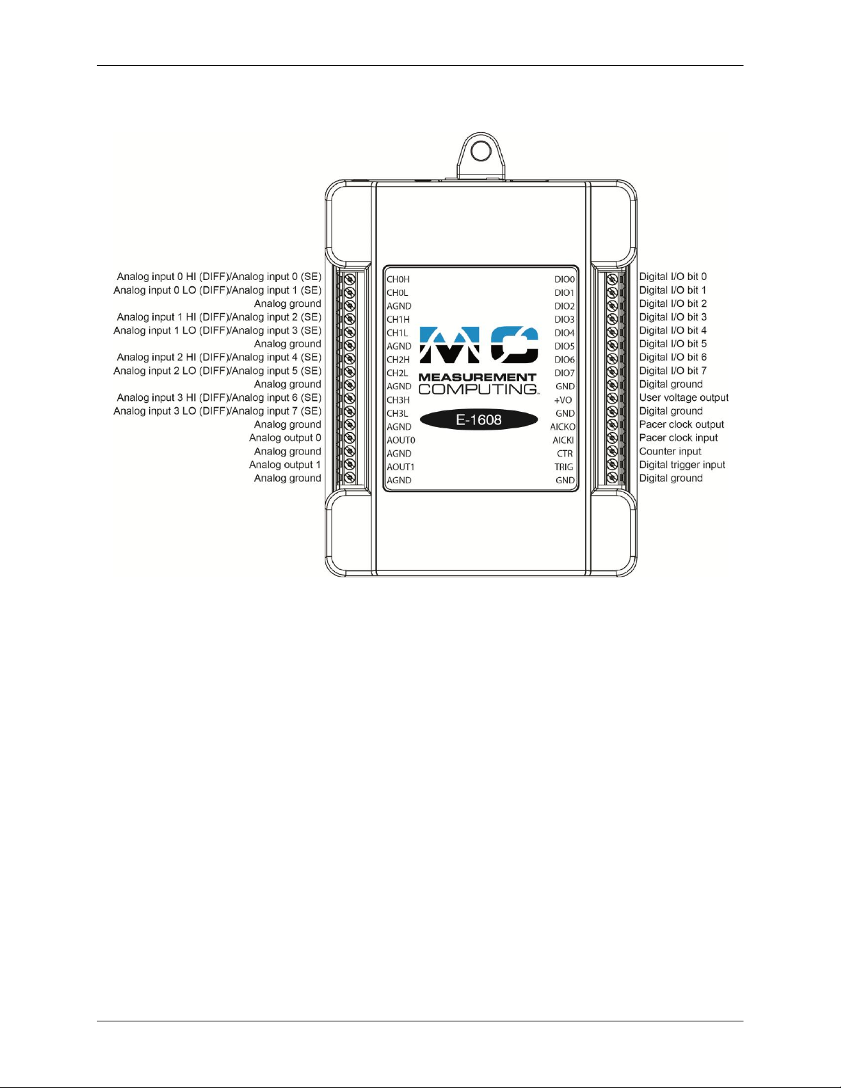
Screw terminals
The E-1608 device screw terminals provide the following connections:
Eight SE or four DIFF (CH0H/CH0L to CH3H/CH3L) analog input connections
Eight digital I/O connections (DIO0 to DIO7)
Two analog output connections (AOUT0, AOUT1)
One external clock input (AICKI) and one external clock output (AICKO) for analog inputs
One digital trigger input (TRIG)
One counter input (CTR)
One power output (+VO)
Six analog ground (AGND) and three digital ground (GND) connections
12
Page 13
E-1608 User's Guide Functional Details
Figure 3. E-1608 pinout
The E-1608 pinout locations are shown in Figure 3 below.
Signal connections
Analog input
You can configure the analog inputs for SE or DIFF mode. The input voltage range is software selectable for
±10 V, ±5 V, ±2 V, or ±1 V.
With SE mode, connect up to eight inputs to CH0x to CH3x. SE mode requires two wires:
Connect one wire to the signal you want to measure (CH#x).
Connect one wire to the analog ground reference (AGND).
With DIFF mode, connect up to four differential inputs to CH0H/CH0L to CH3H/CH3L. DIFF mode requires
two wires plus a ground reference:
Connect one wire to the high/positive signal (CHxH).
Connect one wire to the low/negative signal (CHxL).
Connect one wire to the analog ground reference (AGND).
Floating voltage source
When connecting DIFF voltage inputs to a floating voltage source, make sure the DIFF input channel has a DC
return path to ground. To create this path, connect a resistor from each low channel input to an AGND pin. A
value of approximately 100 kΩ can be used for most applications.
13
Page 14

E-1608 User's Guide Functional Details
Element
Channel
Range
0
CH5
BIP5V
1
CH1
BIP10V
2
CH3
BIP1V
3
CH5
BIP5V
Leave unused input channels either floating or tied to an AGND terminal. Source impedances should be kept as
small as possible to avoid settling time and accuracy errors.
Figure 4 shows DIFF channels 0-3 connected to a ground path resistor.
Figure 4. DIFF connections with ground path resistor
Channel-Gain queue
The channel-gain queue feature allows you to configure a list of channels, modes, and gains for each scan. The
settings are stored in a channel-gain queue list that is written to local memory on the device.
The channel-gain queue list contains one or more channel numbers, modes, and range settings. You can
configure up to 8 elements. The channels can be listed in any order, and can include duplicate channels for
sampling at different ranges.
An example of a 4-element list is shown in the table below.
Sample channel gain queue list (SE mode)
Carefully match the gain to the expected voltage range on the associated channel or an over range condition
may occur. Although this condition does not damage the device, it does produce a useless full-scale reading,
and can introduce a long recovery time due to saturation of the input channel.
For more information about analog signal connections
For more information about analog input connections, refer to the Guide to DAQ Signal Connections (this
document is available on our website at www.mccdaq.com/signals/signals.pdf).
14
Page 15

E-1608 User's Guide Functional Details
1
W3 pull-up/pull-down jumper
Analog output
Two 16-bit analog outputs are available at AOUT0 and AOUT1.
Each analog output channel has an output range of ±10 V. Throughput is system-dependent.
The D/A is software-paced. Each 16-bit analog output (AOUT0 and AOUT1) can be updated simultaneously at
rates from 1000 S/s to 5000 S/s. This is the typical throughput when the device and host are both hard-wired to
the same local network. Typical throughput is not guaranteed if a wireless connection is involved or data is sent
over the Internet.
External clock I/O
The E-1608 provides one external clock input (AICKI) and one clock output (AICKO) for analog inputs.
You can connect an external clock signal to AICKI.
When using the internal clock, AICKO outputs the ADC scan clock.
Digital I/O
You can connect up to eight digital I/O lines to DIO0 through DIO7. Each digital channel is individually
configurable for input or output. The digital I/O terminals can detect the state of any TTL-level input and offer .
advanced BiCMOS output.
Refer to the schematic shown in Figure 5.
Figure 5. Schematic showing switch detection by digital channel DIO0
If you set the switch to the +5 V input, DIO0 reads TRUE (1). If you move the switch to GND, DIO0 reads
FALSE (0).
Pull-up/down configuration
Unconnected inputs are pulled high by default to 5 V through 47 kΩ resistors via jumper W3 on the circuit
board (see Figure 6).
The pull-up/pull-down voltage is common to all 47 kΩ resistors. Jumper W3 is configured by default for pullup.
Figure 6. W3 jumper location
15
Page 16

E-1608 User's Guide Functional Details
Figure 7 shows the jumper configured for pull-up and pull-down.
Caution! The discharge of static electricity can damage some electronic components. Before touching the
board, ground yourself using a wrist strap or touch the computer chassis or other grounded object
to eliminate any stored static charge.
Figure 7. W3 jumper configurations
For more information about digital signal connections
For general information about digital signal connections and digital I/O techniques, refer to the Guide to Signal
Connections (available on our web site at www.mccdaq.com/signals/signals.pdf).
Trigger input
The TRIG terminal is an external digital trigger input. The trigger mode is software selectable for edge or level
sensitive.
Edge sensitive mode is configurable for rising or falling edge.
Level sensitive mode is configurable for high or low level.
The default setting at power up is edge sensitive, rising edge.
Counter input
The CTR terminal is a 32-bit event counter that can accept frequency inputs up to 10 MHz. The internal counter
increments when the TTL levels transition from low to high.
Power output
The +VO terminal can output up to 10 mA maximum. You can use this terminal to supply power to external
devices or circuitry.
Ground
The analog ground (AGND) terminals provide a common ground for all analog channels.
The digital ground (GND) terminals provide a common ground for the digital, counter, timer, and clock
channels and the power terminal.
16
Page 17

E-1608 User's Guide Functional Details
Mechanical drawings
Figure 8. E-1608 device circuit board dimensions
17
Page 18

E-1608 User's Guide Functional Details
Figure 9. E-1608 bottom enclosure dimensions
18
Page 19

E-1608 User's Guide Functional Details
Figure 10. E-1608 top enclosure dimensions
19
Page 20

Parameter
Condition
Specification
A/D converter type
Successive approximation
ADC resolution
16 bits
Number of channels
4 differential, 8 single-ended
Software-selectable
Input voltage range
±10 V, ±5 V, ±2 V, ±1 V; software-selectable per channel
Absolute max input voltage
CHx relative to AGND
±20 V max (power on)
±12 V max (power off)
Input impedance
1 GΩ (power on)
1200 Ω (power off)
Input bias current
±10 nA
Input bandwidth
All input ranges,
small signal (–3 dB)
700 kHz
Input capacitance
60 pf
Max working voltage (signal
+ common mode)
±10 V range
±10.2 V max relative to AGND
±5 V range
±10.2 V max relative to AGND
±2 V range
±9.5 V max relative to AGND
±1 V range
±9.0 V max relative to AGND
Common mode rejection ratio
(fIN = 60 Hz, all input
ranges)
86 dB
Crosstalk
Adjacent differential mode
channels, DC to 10 kHz
–75 dB
Input coupling
DC
Sample rate
0.019 Hz to 250 kHz
Software-selectable
Trigger source
TRIG (see External trigger on page 23)
Sample clock source
Internal A/D clock or external A/D clock (AICKI pin)
Internal sample clock stability
±50 ppm
Internal sample clock
timebase
80 MHz timer with 32-bit period
(available frequencies are 80 MHz / integer period)
Throughput
Software paced
1000 to 5000 S/s typ, on local network (Note 1)
Hardware paced
250 kS/s max
Channel gain queue
Up to 8 elements
Software-selectable channel and range for each queue
element
Warm-up time
15 minutes min
Specifications
All specifications are subject to change without notice.
Typical for 25 °C unless otherwise specified.
Specifications in italic text are guaranteed by design.
Analog input
Table 1. General analog input specifications
Chapter 4
Note 1: This is the typical throughput when the device and host are both connected by Ethernet to the same
local network. The throughput can vary significantly if a wireless connection is involved or data is sent
over the internet and is not guaranteed.
20
Page 21

E-1608 User's Guide Specifications
Range
Gain error
(% of reading)
Offset error
(µV)
INL error
(% of range)
Absolute
accuracy at
Full Scale
(µV)
Gain
temperature
coefficient
(% reading/°C)
Offset
temperature
coefficient
(µV/°C)
±10 V
0.024
915
0.0076
4075
0.0014
47
±5 V
0.024
686
0.0076
2266
0.0014
24
±2 V
0.024
336
0.0076
968
0.0014
10
±1 V
0.024
245
0.0076
561
0.0014
5
Range
Counts
LSBrms
±10 V
6
0.91
±5 V
6
0.91
±2 V
7
1.06
±1 V
9
1.36
Range
4 µS settling accuracy (% FSR)
6 µS settling accuracy (% FSR)
10 µS settling accuracy (% FSR)
±10 V
0.0061
0.0031
0.0015
±5 V
0.0061
0.0031
0.0015
±2 V
0.0061
0.0031
0.0015
±1 V
0.0061
0.0031
0.0015
Parameter
Condition
Specification
Number of channels
2 Resolution
16 bits
Output ranges
Calibrated
±10 V
Output transient
Powered on
Duration: 5 ms
Amplitude: 2 V p-p
Powered off
Duration: 400 ms
Amplitude: 10 V p-p
Differential
non-linearity
16-bit monotonic
±0.35 LSB typ
±1 LSB max
Output current
AOUTx pins
±3.5 mA max (Note 2)
Accuracy
Analog input DC voltage measurement accuracy
Table 2. DC Accuracy components and specifications. All values are (±)
Noise performance
For the peak-to-peak noise distribution test, a differential input channel is connected to AGND at the input
terminal block, and 16384 samples are acquired at the maximum rate available at each setting.
Table 3. Noise performance specifications
Settling time
Settling time is defined as the accuracy that can be expected after one conversion when switching from a
channel with a DC input at one extreme of full scale to another channel with a DC input at the other extreme of
full scale. Both input channels are configured for the same input range.
Table 4. Input settling time specifications in µS, typical
Analog output
Table 5. Analog output specifications
21
Page 22

E-1608 User's Guide Specifications
Parameter
Condition
Specification
Output coupling
DC
Power on and
reset state
DACs cleared to uncalibrated zero-scale: 0 V, ±50 mV unless the alarm
function is enabled for the output (Note 3)
Alarm functionality
Either or both outputs may be configured to go to defined values when
an Ethernet connection with a host is established or lost.
Output update rate
1000 to 5000 S/s typ, on local network (Note 4)
Slew rate
5 V/µs
Throughput
Software paced
1000 to 5000 S/s typ, on local network (Note 4)
Range
Absolute accuracy (±LSB)
±10 V
18.7
Range
% of reading
Offset
(±mV)
Offset tempco
(µV/°C)
Gain tempco
(ppm of range/°C)
±10 V
± 0.024
2.2
30.1
13.2
Range
Relative accuracy (INL)
±10 V
4.0 typ
Parameter
Specification
Recommended warm-up time
15 minutes min
Calibration method
Factory
Calibration interval
1 year (factory calibration)
Parameter
Specification
Digital type
5 V TTL input / advanced BiCMOS output
Number of I/O
8
Configuration
Independently configured for input or output
Pull-up configuration
All pins pulled up to 5 V using 47 K resistors (default).
Can be changed to pull-down using an internal jumper.
Digital I/O transfer rate
(system-paced)
100 to 5000 port reads/writes or single bit reads/writes per second typ, on local
network (Note 5)
Alarm functionality
Any combination of DIO bits may be configured to become outputs and go to defined
values when an Ethernet connection with a host is established or lost.
Power on and reset state
All bits are input unless the alarm functionality is enabled for them.
Note 2: Leave unused AOUTx output channels disconnected.
Note 3: AOUTx defaults to 0 V whenever the device is powered on or a reset command is issued to the device,
unless the alarm functionality is enabled for the output.
Note 4: This is the typical throughput when the device and host are both connected by Ethernet to the same
local network. The throughput can vary significantly, and typical throughput is not guaranteed if a
wireless connection is involved or data is sent over the internet.
Table 6. Calibrated absolute accuracy specifications
Table 7. Calibrated absolute accuracy components specifications
Table 8. Relative accuracy specifications (±LSB)
Analog input/output calibration
Table 9. Analog input/output calibration specifications
Digital input/output
Table 10. Digital input/output specifications
22
Page 23

E-1608 User's Guide Specifications
Parameter
Specification
Input high voltage threshold
2.0 V min
Input high voltage limit
5.5 V absolute max
Input low voltage threshold
0.8 V max
Input low voltage limit
–0.5 V absolute min
0 V recommended min
Output high voltage
3.8 V typ at no load
3.0 V min (IOH = –3 mA)
2.0 V min (IOH = –32 mA)
Output low voltage
0.15 V typ at no load
0.55 V max (IOL = 64 mA)
Power on and reset state
Input
Parameter
Condition
Specification
Trigger source
External digital
TRIG
Trigger mode
Software-selectable
Edge or level sensitive: user configurable for CMOS
compatible rising or falling edge, high or low level.
Trigger latency
2 µs + 1 pacer clock cycle max
Trigger pulse width
1 µs min
Input type
Schmitt trigger, 47 kΩ pull-down to ground
Schmitt trigger hysteresis
1.01 V typ
0.6 V min
1.5 V max
Input high voltage threshold
2.43 V typ
1.9 V min
3.1 V max
Input high voltage limit
5.5 V absolute max
Input low voltage threshold
1.42 V typ
1.0 V min
2.0 V max
Input low voltage limit
–0.5 V absolute min
0 V recommended min
Parameter
Specification
Terminal names
AICKI, AICKO
Terminal types
AICKI: Input (receives A/D pacer clock from external source)
AICKO: Output (outputs internal A/D pacer clock)
Input clock rate
250 kHz max
Clock pulse width
AICKI: 1 µs min
AICKO: 1.8 µs min
Clock mode
Edge-sensitive, rising
Input type
Schmitt trigger, 47 kΩ pull-down to ground
Note 5: This is the typical throughput when the device and host are both connected by Ethernet to the same
local network. The throughput can vary significantly, and typical throughput is not guaranteed if a
wireless connection is involved or data is sent over the internet.
External trigger
Table 11. External trigger specifications
External clock input/output
Table 12. External clock I/O specifications
23
Page 24

E-1608 User's Guide Specifications
Parameter
Specification
Schmitt trigger hysteresis
1.01 V typ
0.6 V min
1.5 V max
Input high voltage threshold
2.43 V typ
1.9 V min
3.1 V max
Input high voltage limit
5.5 V absolute max
Input low voltage threshold
1.42 V typ
1.0 V min
2.0 V max
Input low voltage limit
–0.5 V absolute min
0 V recommended min
Output high voltage
4.4 V min (IOH = –50 µA)
3.80 V min (IOH = –8 mA)
Output low voltage
0.1 V max (IOL = 50 µA)
0.44 V max (IOL = 8 mA)
Parameter
Specification
Pin name
CTR
Counter type
Event counter
Number of channels
1
Input type
Schmitt trigger, 47 kΩ pull-down to ground
Input source
CTR screw terminal
Resolution
32 bits
Schmitt trigger hysteresis
1.01 V typ
0.6 V min
1.5 V max
Input high voltage threshold
2.43 V typ
1.9 V min
3.1 V max
Input high voltage limit
5.5 V absolute max
Input low voltage threshold
1.42 V typ
1.0 V min
2.0 V max
Input low voltage limit
–0.5 V absolute min
0 V recommended min
Input frequency
10 MHz max
High pulse width
50 ns min
Low pulse width
50 ns min
Parameter
Specification
Data FIFO (analog input)
49,152 samples
Non-volatile memory
2,048 bytes (768 bytes for calibration, 256 bytes for user, 1,024 bytes for network
settings)
Counter
Table 13. Counter specifications
Memory
Table 14. Memory specifications
24
Page 25

E-1608 User's Guide Specifications
Parameter
Condition
Specification
External power supply
5V, 1A
Supply current
Quiescent current
330 mA typical (Note 6)
710 mA max including all external loading
User output voltage range
Available at +VO terminal
4.40 V min to 5.25 V max, assumes supplied
AC adapter is used
User output current
Available at +VO terminal
10 mA max
Parameter
Specification
Ethernet type
100 Base-TX
10 Base-T
Communication rates
10/100 Mbps, auto-negotiated
Connector
RJ-45, 8 position
Cable length
100 meters max
Additional parameters
HP Auto-MDIX support
Parameter
Specification
Protocols used
TCP/IP (IPv4 only), UDP
Network ports used
UDP:54211 (discovery)
UDP:6234 (bootloader only)
TCP:54211 (commands)
TCP:54212 (scan data)
Network IP configuration
DHCP + link-local, DHCP, static, link-local
Network name
E-1608-xxxxxx, where xxxxxx are the lower 6 digits of the device MAC address
Network name publication
By NBNS (responds to b-node broadcasts, therefore only available on the local
subnet)
Power
Table 15. Power specifications
Note 6: This is the total quiescent current requirement for the device that includes the LEDs. This does not
include any potential loading of the digital I/O bits, +VO terminal, or the AOUTx outputs.
Network
Ethernet connection
Table 16. Ethernet connection specifications
Network interface
Table 17. Factory default specifications
25
Page 26

E-1608 User's Guide Specifications
Parameter
Specification
Factory default IP address
192.168.0.101
Factory default subnet mask
255.255.255.0
Factory default Gateway
192.168.0.1
Factory default DHCP setting
DHCP + link-local enabled
Parameter
Specification
Security implementation
TCP sockets are not opened unless application sends the correct PIN code (stored in
non-volatile memory, may be changed by user, default value 0000)
Number of concurrent sessions
1
Vulnerabilities
TCP Sequence Number Approximation Vulnerability
Parameter
Specification
Power LED (top)
3.3 V < V
ext
< 5.9 V: On
V
ext
< 3.3 V, V
ext
> 5.9 V: Off (power fault)
Activity LED (bottom)
On when there is a valid host connection and blinks when a command is received or
an AInScan is running.
Ethernet connector LEDS
Left (green): Link/activity indicator; on when there is a valid Ethernet link and
blinks when network activity is detected.
Right (yellow): Speed indicator; on for 100 Mbps, off for 10 Mbps or no link.
Factory reset button
Used to reset the network configuration settings to the factory default values.
Press the button when applying power to the device and continue to hold for
4 seconds; the device LEDs stay off, and then both the Power and Activity LEDs
blink once indicating that the settings have been restored to the defaults.
Release the button so the device continues startup with the default settings. If the
button is released before the two LEDs blink, the settings are not affected and the
device starts up normally.
Parameter
Specification
Operating temperature range
0 °C to 55 °C max
Storage temperature range
–40 °C to 85 °C max
Humidity
0% to 90% non-condensing max
Parameter
Specification
Dimensions (L × W × H)
117.9 × 82.8 × 29.0 mm (4.64 × 3.26 × 1.14 in.)
Network factory default settings
Table 18. Factory default specifications
Network security
Table 19. Factory default specifications
LED displays and the factory reset button
Table 20. LED and button configurations
Environmental
Table 21. Environmental specifications
Mechanical
Table 22. Mechanical specifications
26
Page 27

E-1608 User's Guide Specifications
Parameter
Specification
Connector type
Screw terminal
Wire gauge range
16 AWG to 30 AWG
Pin
Signal name
Pin description
Pin
Signal name
Pin description
1
CH0H
Channel 0 high (SE channel 0)
17
DIO0
Digital I/O bit 0
2
CH0L
Channel 0 low (SE channel 1)
18
DIO1
Digital I/O bit 1
3
AGND
Analog ground
19
DIO2
Digital I/O bit 2
4
CH1H
Channel 1 high (SE channel 2)
20
DIO3
Digital I/O bit 3
5
CH1L
Channel 1 low (SE channel 3)
21
DIO4
Digital I/O bit 4
6
AGND
Analog ground
22
DIO5
Digital I/O bit 5
7
CH2H
Channel 2 high (SE channel 4)
23
DIO6
Digital I/O bit 6
8
CH2L
Channel 2 low (SE channel 5)
24
DIO7
Digital I/O bit 7
9
AGND
Analog ground
25
GND
Digital ground
10
CH3H
Channel 3 high (SE channel 6)
26
+VO
User voltage output
11
CH3L
Channel 3 low (SE channel 7)
27
GND
Digital ground
12
AGND
Analog ground
28
AICKO
External clock pacer output
13
AOUT0
Analog output 0
29
AICKI
External clock pacer input
14
AGND
Analog ground
30
CTR
Counter input
15
AOUT1
Analog output 1
31
TRIG
Digital trigger input
16
AGND
Analog ground
32
GND
Digital ground
Screw terminal connector
Table 23. Screw terminal connector specifications
Table 24. Screw terminal pinout
27
Page 28

Declaration of Conformity
According to ISO/IEC 17050-1:2010
Manufacturer: Measurement Computing Corporation
Address: 10 Commerce Way
Suite 1008
Norton, MA 02766
USA
Product Category: Electrical equipment for measurement, control and laboratory use.
Date and Place of Issue: September 29, 2014, Norton, Massachusetts USA
Measurement Computing Corporation declares under sole responsibility that the product
E-1608
Complies with the essential requirements of the following applicable European Directives:
Electromagnetic Compatibility (EMC) Directive 2004/108/EC
Low Voltage Directive 2006/95/EC
RoHS Directive 2011/65/EU
Conformity is assessed in accordance to the following standards:
EMC:
Emissions:
EN 61326-1:2013 (IEC 61326-1:2012), Class A
EN 55011: 2009 + A1:2010 (IEC CISPR 11:2009 + A1:2010), Group 1, Class A
Immunity:
EN 61326-1:2013 (IEC 61326-1:2012), Controlled EM Environments
EN 61000-4-2:2008 (IEC 61000-4-2:2008)
EN 61000-4-3 :2010 (IEC61000-4-3:2010)
EN 61000-4-4 :2012 (IEC61000-4-4:2012)
EN 61000-4-5 :2005 (IEC61000-4-5:2005)
EN 61000-4-6 :2013 (IEC61000-4-6:2013)
EN 61000-4-11:2004 (IEC61000-4-11:2004)
Safety:
EN 61010-1 (IEC61010-1)
Environmental Affairs:
Articles manufactured on or after the Date of Issue of this Declaration of Conformity do not
contain any of the restricted substances in concentrations/applications not permitted by the RoHS
Directive.
Carl Haapaoja, Director of Quality Assurance
Page 29

Measurement Computing Corporation
10 Commerce Way
Suite 1008
Norton, Massachusetts 02766
(508) 946-5100
Fax: (508) 946-9500
E-mail: info@mccdaq.com
www.mccdaq.com
 Loading...