

Page 1
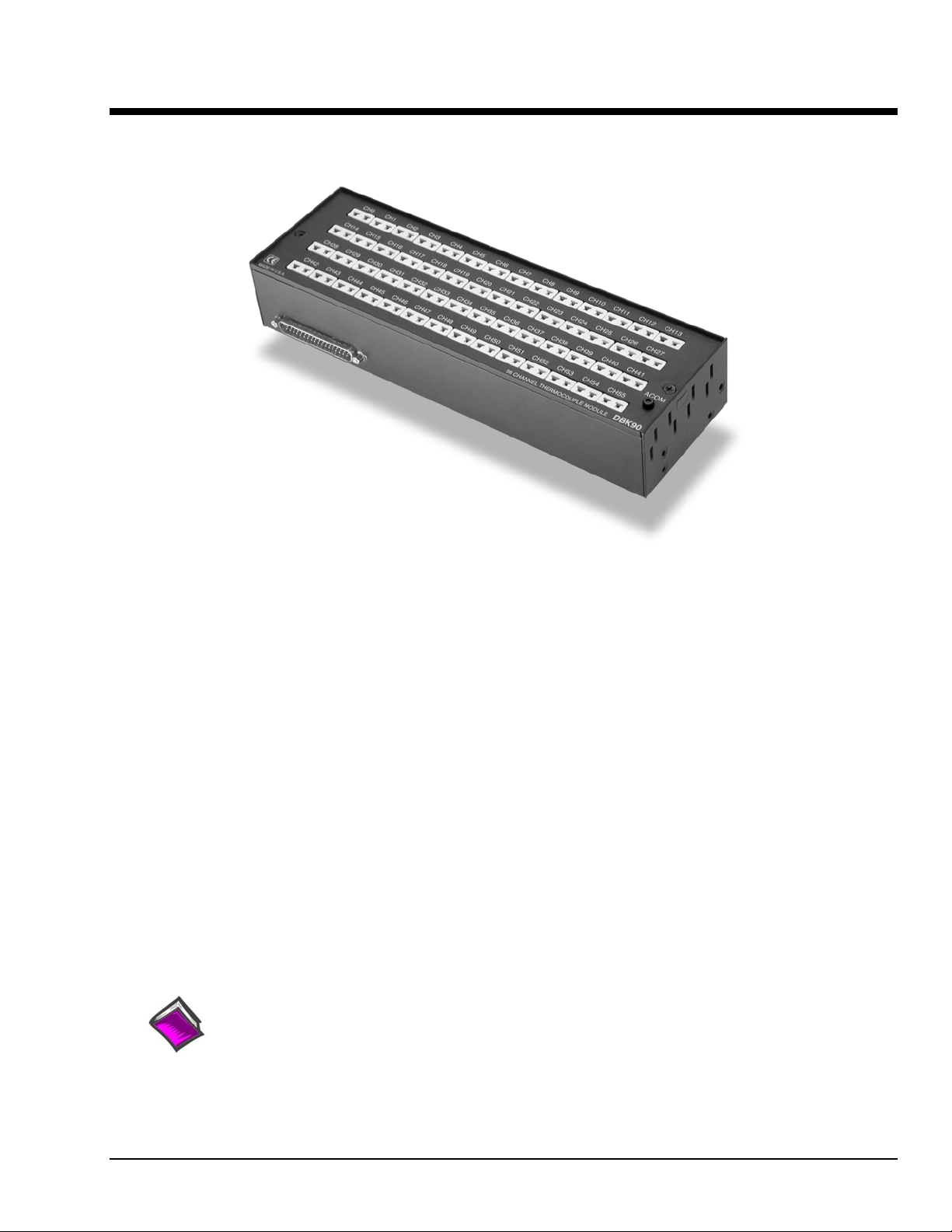
DBK90 56-Channel Thermocouple Module
For use with DaqBook/2000 Series Devices, WBK40, & WBK41
Overview …… 2
Hardware Setup …… 3
Connecting DBK90 Modules to Thermocouples …… 3
Open Thermocouple Detection …… 4
Module Configuration …… 4
Connecting DBK90 Modules to other Devices ……5
Mounting…
DBK90 Modules to Each Other…… 5
One or two DBK90 Modules to a Primary Data Acquisition Device…...6
One, two, or three DBK90 Modules to a DBK60 ……7
DBK90 to a Rack ……8
Vehicle Testing and Noise Reduction……9
Power Connections and Analog Common …… 9
Shielding ……10
TC Common Mode …… 10
Software Setup …… 11
Using a Temperature Calibrator …… 12
DBK90 – Specifications …… 13
Reference Notes:
o Chapter 2 includes pinouts for P1, P2, P3, and P4. Refer to pinouts applicable to your system,
DBK Option Cards and Module 907492 DBK90 pg. 1
as needed.
o In regard to calculating system power requirements, refer to DBK Basics located near
the front of this manual.
Page 2
Overview
The DBK90 is used in temperature measurement applications and provides connections for 56
thermocouples through convenient mini-TC connectors.
The DBK90 features on-board cold junction compensation (CJC) for direct measurement of type
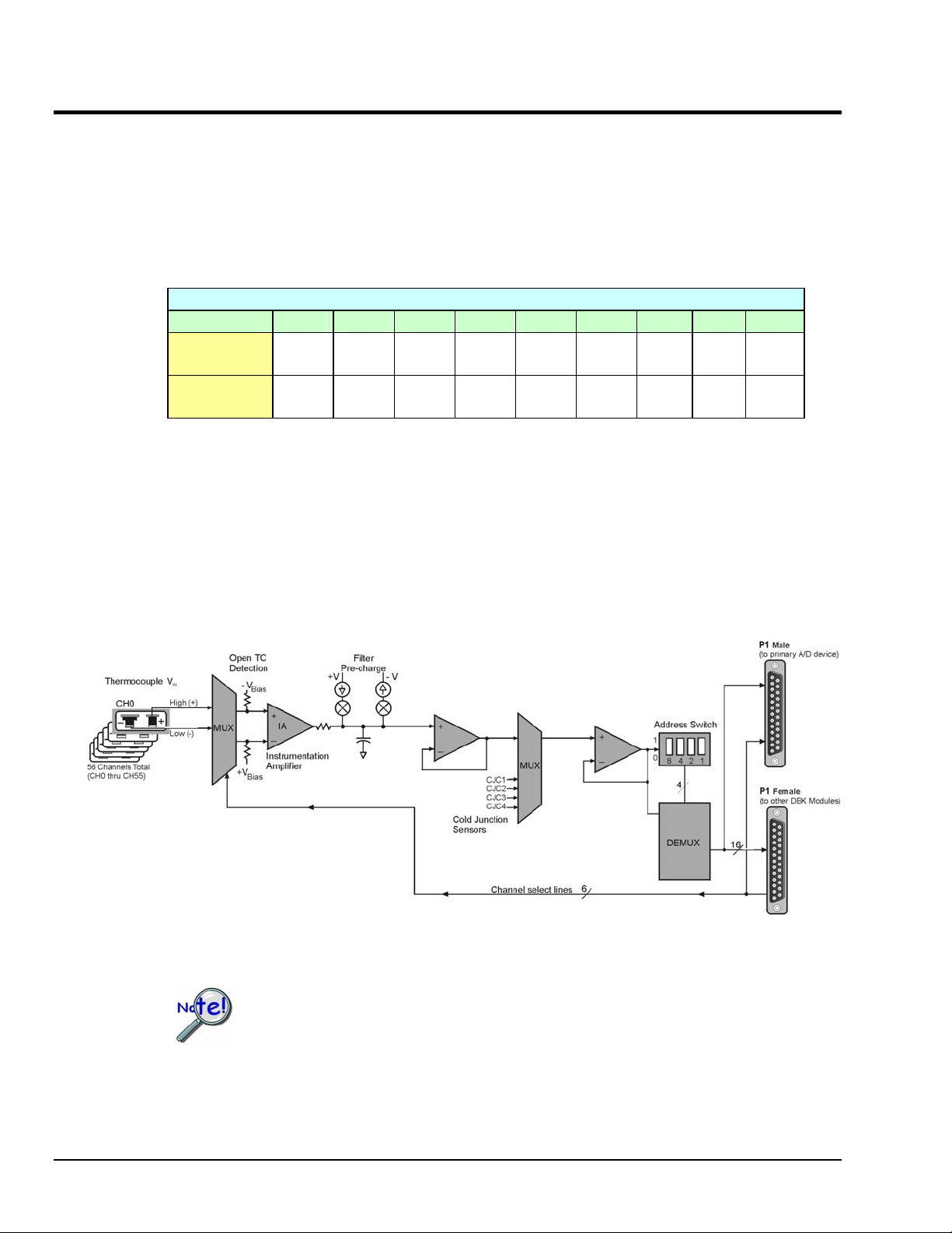
J, K, T, E, N28, N14, S, R, and B thermocouples. The following table provides the temperature
range for each of these thermocouple types.
Thermocouple Temperature Ranges
T/C Type J K T E N28 N14 S R B
Temperature
Range °C
Temperature
Range °F
-200 to
760
-328 to
1400
-200 to
1200
-328 to
2192
-200 to
400
-328 to
752
-270 to
650
-454 to
1202
-270 to
400
-454 to
752
0 to
1300
32 to
2372
-50 to
1768
-58 to
3214
-50 to
1768
-58 to
3214
Note: There are four CJCs on the DBK90, one per row of thermocouple connectors.
50 to
1780
122 to
3236
Up to sixteen DBK90 modules can be attached to a single DaqBook/2000 Series device, WBK40, or
WBK41. Using Sixteen DBK90 modules provides up to 896 temperature channels.
DBK90 Block Diagram
In comparison to typical DBK options, the DBK90 demands significant power from the
system’s ±15 V power supplies. It is important that you calculate your system’s power
demand, as you may need to add auxiliary power supplies. For additional information
refer to Power Requirements in the DBK Basics section.
pg. 2, DBK90 907492 DBK Option Cards and Modules
Page 3
Hardware Setup
Connecting DBK90 Modules to Thermocouples
The DBK90 accepts up to 56 mini-TC plugs in its channels 0 through 55. All channels have the same level
of functionality.
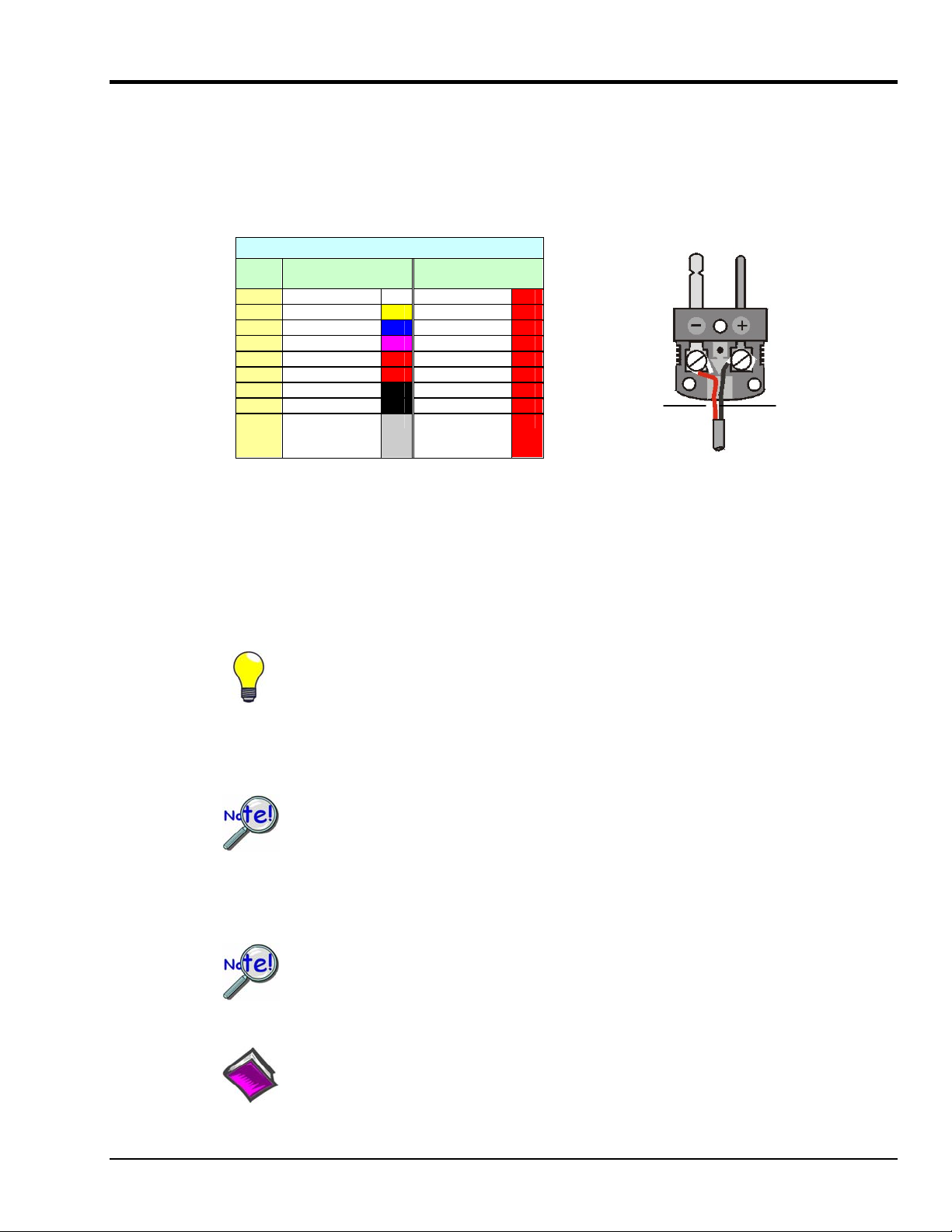
Thermocouple wire is standardized, color-coded, and polarized, as noted in the following table.
Thermocouple Standards
T/C
Type
J White Red
K Yellow Red
T Blue Red
E Violet Red
N28 Orange Red
N14 Orange Red
S Black Red
R Black Red
B Gray Red
Mini-TC plugs are type-specific, and for best measurement operation the plug TC type should match the
wire TC type. If necessary, copper/copper (Type U) plugs may be used, but measurement stability will be
slightly degraded. Mini-TC plugs are polarized as well, and it is critical for proper measurement operation
that this polarity be followed when connecting the thermocouple wire. Once wired, the TC plugs will only
mate into the DBK90’s connectors in one orientation, ensuring a correct connection.
(+) Lead to
Channel High
(-) Lead to
Channel Low
Red (-) connects
to Channel Low
The (+) color,
see table,
connects to
Channel High
It should be noted that thermocouples output very small voltages and that long thermocouple leads can
pickup a large amount of noise. If desired, noise reduction can be achieved through the use of shielded
thermocouples and/or averaging.
You can minimize the effect of noise by (1) using shielded thermocouples,
(2) averaging readings, or (3) employing both of these practices.
Each DBK90 includes a jack labeled “ACOM.” The jack is typically used for connecting the shield of a
shielded thermocouple to the DBK90’s analog common. When this connection is made the shield at the
other end of the thermocouple is left unconnected.
If a thermocouple shield is connected to the DBK90 module, leave the shield
unconnected at the other end of the thermocouple. Connecting the shield to common
at both ends will result in a ground loop.
The jack accepts a removable 2mm banana plug for ease of making and breaking the analog common
connection. The 2mm banana plug that is shipped with the product is part number 5936-0 from Pomona®
Electronics.
The ACOM connector is a 2mm banana jack. To ensure a good connection that will not
damage the jack, use a Pomona® Electronics 2mm banana plug (p/n 5936-0). The use of a
different plug (including a 0.08 inch tip type) may damage the ACOM jack.
Reference Note:
In regard to automotive applications, refer to the upcoming section entitled, Vehicle Testing.
The section begins on page 9.
DBK Option Cards and Module 907492 DBK90 pg. 3
Page 4
Open Thermocouple Detection
The DBK90 is equipped with open thermocouple detection for each channel. This means that a broken
thermocouple wire [or otherwise unconnected input] that is measured will result in an off-scale reading.
This is accomplished by applying a small bias current to each of the channel inputs. Whenever a valid
input is absent, the bias current saturates the input amplifier, resulting in the off-scale reading.
Module Configuration
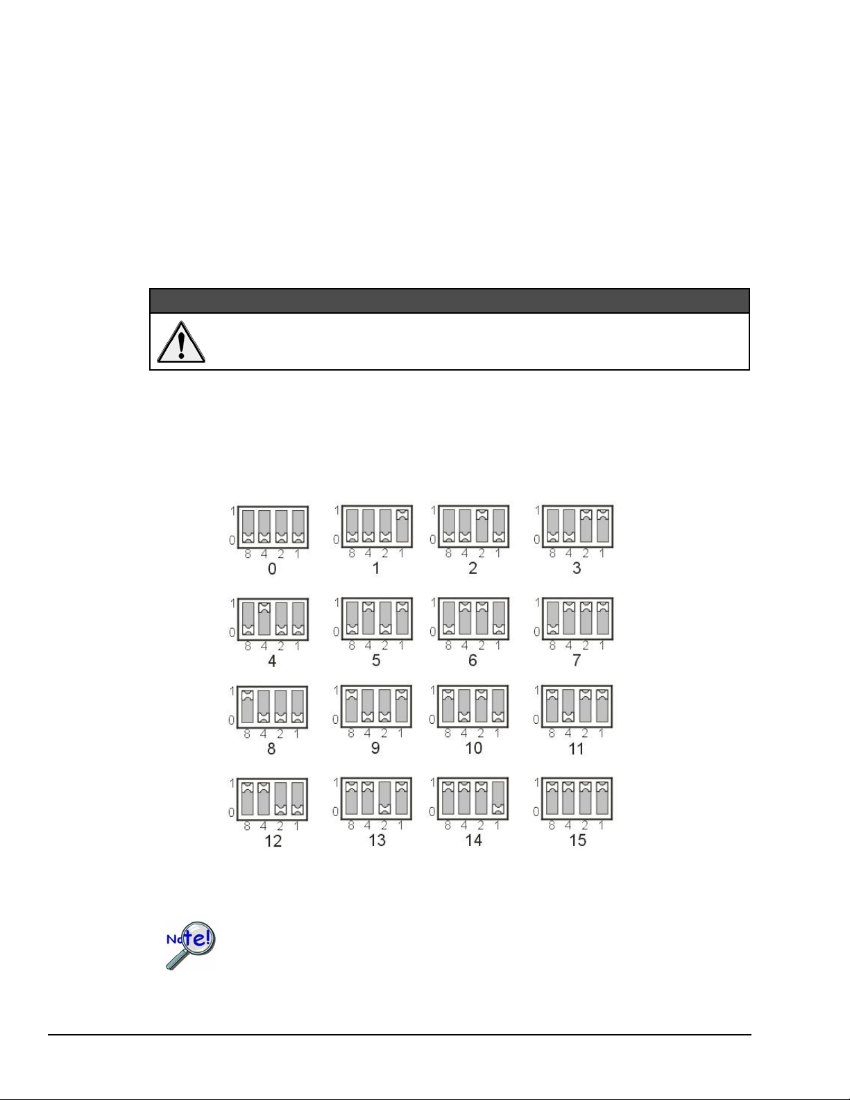
Up to sixteen DBK90 modules can be attached to a single DaqBook/2000 Series device, WBK40, or
WBK41. Since multiple modules are connected via a parallel interface, each must have a unique channel
address.
Adjustment of the channel address must only be performed when the system
power is OFF. Failure to do so may result in equipment damage.
To assign a channel address to the DBK90 module, first locate the DIP switch on the unit’s underside (the
side opposite of the mini-TC connectors). Four micro-switches [on the DIP switch] are used to set the
module’s channel address in binary. After ensuring that the system power is OFF, adjust the microswitches to set the desired address. The following figure shows DIP switch settings for the 16 possible
addresses.
CAUTION
DBK90 Channel Address Settings
Each module in the system must have a unique address.
pg. 4, DBK90 907492 DBK Option Cards and Modules
Page 5
Connecting DBK90 Modules to other Devices
Mounting DBK90 Modules to Each Other – Using Kit # 1109-0800
Each 1109-0800 mounting kit includes two splice bars and eight screws. The kit is only intended for
mounting one DBK90 module to another. However, other kits are available for mounting DBK90s to
primary acquisition devices, for example, to a DaqBook/2000 Series device. Those kits are discussed
shortly.
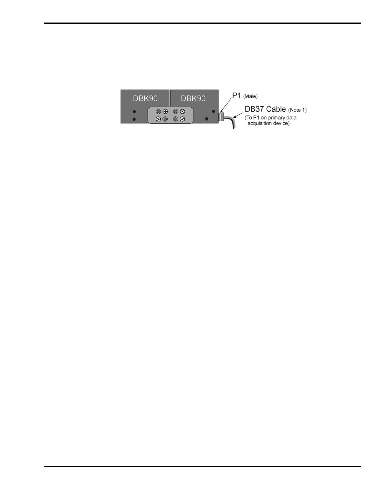
Two DBK90 Modules, Combined via Kit # 1109-0800
Follow these steps if you desire to mount DBK90 modules to each other using 8-hole splice bars.
1. Push the two DBK90 modules together such that their P1 connectors properly mate. Note that
each DBK90 has a female P1 DB37 connector on one side and a male P1 DB37 connector on
the other.
2. Align four holes of an 8-hole splice bar as indicated in the preceding figure. Note that the two
holes for one DBK90 will be vertical, while the two holes for the other DBK90 will be
diagonal (see figure).
3. Secure the splice bar to the DBK90 modules using the provided screws.
The screws are 8-32 x 1/4 Phillips Pan Head Screws.
4. Use the second splice bar and set of 4 screws, to secure the other side of the assembly.
Note: Additional splice bar kits can be used to add more DBK90 modules to the assembly.
5. Connect one end of a DB37 cable to the DBK90 male P1 connector (see figure).
6. Connect the other end of the DB-37 cable to the male P1 connector located on the primary data
acquisition device.
This completes the procedure.
Note 1:
A female-to-female 37 pin connector can be used to connect a DBK90 to the host data
acquisition device. The use of a CA-143-x shielded cable is recommended for scenarios in
which signal noise is a problem. Page 14 of this section includes a list of cables compatible
with DBK90 use.
DBK Option Cards and Module 907492 DBK90 pg. 5
Page 6

Mounting one or two DBK90 Modules to a Primary Data Acquisition Device –
Using Kit # 1109-0802
: Kit 1109-0802 is for use with a primary data acquisition device that has
Note
no molded protective ears. The ears would interfere with the kit’s splice plates.
Mounting kit p/n 1109-0802 includes two splice plates and the associated screws for securing the plates to
the main data acquisition device, and then securing up to two DBK90 modules to the plates. An optional
handle can be added, as discussed in step 1.
Two DBK90 Modules mounted to a DaqBook/2000E, via Kit # 1109-0802
Note that the DaqBook/2000 Series devices and the kit’s splice-plates each have a length of 8.5 inches.
1. If you are attaching an optional handle:
(a) Position the handle’s mounting holes over the indicated holes in one splice plate.
(b) Secure the handle by threading screws through the counter-sunk holes on the opposite
side of the splice plate.
2. Align the lower two screw-holes of one splice-plate with the mating holes on the primary
acquisition device.
3. Secure the splice-plate using two of the provided screws. The screws are 8-32 x 1/4 Phillips
Pan Head Screws.
4. Mount the second splice-plate to the other side of the acquisition device.
5. Position a DBK90 module such that its male P1 connector is located on the same plane as the
P1 connector on the primary device.
6. With the screw holes of the DBK90 aligned with those of a splice-plate (see figure), secure the
module to the plate. Repeat this step for the other side of the module.
7. If you are connecting a second DBK90 module:
(a) Mate the male P1 connector of the second DBK90 module with the female P1
connector of the first DBK90 module.
(b) Secure the second DBK90 module to the two splice plates using two screws per side
(see figure).
8. Connect one end of a DB37 cable to the first DBK90’s P1 male connector (see figure).
9. Connect the other end of the CA-37 cable to the male P1 connector of the data acquisition
device.
This completes the procedure.
Note 1:
pg. 6, DBK90 907492 DBK Option Cards and Modules
A female-to-female 37 pin connector can be used to connect a DBK90 to the host data
acquisition device. The use of a CA-143-x shielded cable is recommended for scenarios in
which signal noise is a problem. Page 14 of this section includes a list of cables compatible
with DBK90 use.
Page 7

Mounting one, two, or three DBK90 Modules to a DBK60 – Using Kit # 1109-0803
Mounting kit p/n 1109-0803 is used to mount up to three DBK90 modules to a DBK60. The mounting kit
includes two splice plates and the necessary screws.
: Kit 1109-0803 is for use with a DBK60 that has no molded protective ears.
Note
The ears would interfere with the kit’s splice plates.
Three DBK90 Modules Mounted to a DBK60 via Kit # 1109-0803
Note that the DBK60 and the splice-plates each have a length of 13 inches.
1. If you are attaching an optional handle:
(a) Position the handle’s mounting holes over the indicated holes in one splice plate.
(b) Secure the handle by threading screws through the counter-sunk holes on the
opposite side of the splice plate.
2. Align the lower three screw-holes of the splice-plate with the mating holes on the DBK60.
Note 1:
3. Secure the splice-plate to the DBK60 using three of the provided screws. Note that the
screws are 8-32 x 1/4 Phillips Pan Head Screws.
4. Secure the second splice-plate to the other side of the DBK60.
5. Position a DBK90 module such that its male P1 connector is located on the same plane as the
P1 connector of the DBK60.
6. Align the two lower screw holes of the DBK90 module with those on the splice-plate [the
side nearest the DBK60’s P1 connector] (see figure).
7. Use two of the provided screws to secure the DBK90 module to the splice-plate. Repeat this
step for the other side of the assembly.
8. If you are connecting a second and/or third DBK90 module:
(a) Mate the female P1 connector of the second [or third] DBK90 module with the male
P1 connector of the previously mounted DBK90 module.
(b) Secure the second [or third] DBK90 module to the two splice-plates using two
screws per side (see figure).
9. Connect one end of a DB37 cable to the first DBK90’s male P1 connector (see figure).
10. Connect the other end of the DB37 cable to the male P1 connector of the DBK60.
A female-to-female 37 pin connector can be used to connect a DBK90 to the host data
acquisition device. The use of a CA-143-x shielded cable is recommended for scenarios in
which signal noise is a problem. Page 14 of this section includes a list of cables compatible
with DBK90 use.
This completes the procedure.
DBK Option Cards and Module 907492 DBK90 pg. 7
Page 8

Mounting a DBK90 to a Rack – Using Rack-Mount Kit # 1109-0801
You can use Rack-Mount Kit # 1109-0801 to mount a DBK90 module to a standard instrument rack. The
kit includes 2 rack mount ears, 2 rack-mount extenders, 4 button-head hex screws, 4 Phillips flathead
screws, and a hex wrench.
Rack-Mount Kit # 1109-0801
Refer to the figures and to the following steps to prepare a DBK90 module for rack mounting.
Mounting an Ear/Extender Assembly to a DBK90
1. Align the screw-holes of a Rack-Mount Ear to the matching holes on a Rack-Mount Extender.
2. Fasten the two parts together using 2 of the Phillips Flathead Screws. The Ear/Extender
assembly should resemble the one in the above illustration.
3. Using 2 Button-head Hex Screws, secure the Ear/Extender assembly to the DBK90 module.
Proper orientation is indicated in the above figure.
4. Using the Hex Wrench [provided], tighten the Hex Screws.
5. Repeat steps 1 through 4 for assembling the remaining Ear/Extender components and attaching
them to the other side of the DBK90.
At this point the assembly can be mounted to a standard instrument rack.
pg. 8, DBK90 907492 DBK Option Cards and Modules
Page 9

Vehicle Testing and Noise Reduction
Power Connections and Analog Common
To properly measure vehicle-attached thermocouples differentially, it is necessary to have an analog common
connection to the negative side of the vehicle’s electrical system. A jack labeled ACOM, located on the DBK90’s
mini-TC panel, provides a connection point for analog common. If analog common is not connected, true
differential readings cannot be obtained due to noise. For this reason, the chassis of the primary data acquisition
device, e.g., DaqBook/2000A, must also have a good connection to the negative side of the vehicle’s electrical
system.
All grounds should come together at the negative terminal of the test vehicle’s battery. Connecting the grounds at
any other point may introduce noise. One line, with a 2mm banana plug is used to connect the battery’s negative
terminal to the DBK90’s ACOM jack. The ACOM jack connects internally to the DBK90’s P1, pin # 28 (AGND).
Connections for a Vehicle Test
Note 1: The ACOM connector is a 2mm banana jack. To ensure a good connection that will not
damage the jack, use a Pomona® Electronics 2mm banana plug (p/n 5936-0). The use
of a different plug (including a 0.08 inch tip type) may damage the ACOM jack.
Note 2: It is best to use a male DIN5 connector to connect the lines from the battery to the
DaqBook/2000’s female DIN5 connector. A Switchcraft® male DIN5 Connector
(p/n 12BL5M) can be used for making your own cable.
The lines that will connect to the vehicle battery are soldered to the male DIN5 connector. As indicated in the first
figure on this page, the +V
series with the line. The -V
DBK Option Cards and Module 907492 DBK90 pg. 9
line connects to the battery’s positive (+) terminal and should have a 7.5 amp fuse in
IN
and Chassis Ground lines both connect to the battery’s negative terminal.
IN
Page 10

Shielding
Using shielded TC wire with the shield connected to analog common [DBK90’s ACOM jack] will result in further
noise reduction. Using a shielded ribbon cable to connect the DBK90’s male P1 connector to the P1 connector of
the primary data acquisition device will also help minimize noise. CA-143-7 and CA-143-18 are female-to-female,
DB37 shielded ribbon cables of 7-inch and 18-inch lengths, respectively.
If a thermocouple shield is connected to the DBK90 module, leave the shield unconnected at the
other end of the thermocouple. Connecting the shield to common at both ends will result in a
ground loop.
TC Common Mode
The maximum common-mode voltage for the DBK90 is ±10 volts. Common-mode voltage is the DC or AC voltage
signal that is applied equally to both sides of a differential input.
If a thermocouple is connected directly to a component in the vehicle at a potential that is over the maximum
common-mode voltage, then very noisy or incorrect readings will be seen. Thermocouple connections that are
made directly to the alternator or engine block may also result in high noise. Two methods of reducing noise are:
(a) Run a ground line from the bolt, as indicated in the first figure.
(b) Isolate the thermocouple leads with a set of washers, one of which is mica.
This is indicated in the second figure.
Running a Ground Wire to the Battery’s Negative Terminal
The length of the shoulder
washer’s hub must not exceed
the combined thickness of the
terminal ring and mica washer.
Using a Washer Set and Heat Sink to Isolate the Thermocouple
A thin layer of heat-sink
compound on the indicated
surfaces will improve
thermal conductivity.
pg. 10, DBK90 907492 DBK Option Cards and Modules
Page 11

Software Setup
Note: DaqView includes functions for the conversion and linearization of thermocouple readings into
When a DBK90 is selected in DaqView, thermocouple types must also be selected for the module’s
channels. The steps for this are as follows:
In the DaqView figure below we see that J-type thermocouples have been selected for a DBK90 module’s
Channels 0 through 25; possibly more, but we would have to scroll down to view information for the other
channels. Note that channel 0 is designated as P1 0-0 and that channel 1 is seen as P1 0-1. The “0”
indicates that the DBK90 module is the first such module in the acquisition system. A second DBK90
module would list channel 0 as P1 1-0 and would show channel 1 as P1 1-1. A third module would have
P1 2-0, P1 2-1, and so on …
Reference Notes:
o DaqView users - Refer to DBK Setup in the DaqView PDF.
o Programmers using Daq devices should refer to related sections in the Programmer’s
Manual.
temperature data.
1. In DaqView’s Configure System Hardware Window, select DBK90.
2. From the Channel Setup Tab (following figure) select the thermocouple types as applicable.
Do this for each channel.
Note: Channel types can be changed by double-clicking in the Type column, or by using the
Channel Type pull-down list.
DaqView, Channel Setup
DBK Option Cards and Module 907492 DBK90 pg. 11
Page 12

Using a Temperature Calibrator
The DBK90 thermocouple module provides accurate and repeatable temperature measurements across a
wide range of operating conditions. However, all instrumentation is subject to drift with time and with
ambient temperature change.
Note: The ambient temperature should be stabilized for at least one hour.
If the ambient temperature of the operating environment is below 18°C or above 28°C, or if the product is
near or outside its one-year calibration interval, then the absolute accuracy may be improved through the
use of an external temperature calibrator.
A temperature calibrator is a temperature simulation instrument that allows selection of thermocouple type
and temperature. For proper operation, it must be connected to the DBK90 with the same type
thermocouple wire and connector that is used in normal testing. The calibrator then generates and supplies
a voltage to the module. The supplied voltage corresponds to that which would be generated by the chosen
thermocouple type at the selected temperature.
The temperature selected on the calibrator will be dictated by the nature of normal testing. 0°C is usually
the best choice. Calibrators are the most accurate at this setting, and the connecting thermocouple wire will
contribute very little error at this temperature. However, if the dynamic range of the normal testing is, for
example, 100°C to 300°C, a selection of 200°C may give better results. In either case, the level of
adjustment is determined by comparing the unit reading to the selected calibrator temperature. For
example, if the calibrator is set to 0°C output, and the DBK unit reads 0.3°C, then an adjustment of –0.3°C
is required. That is, the adjustment value is determined by subtracting the DBK reading from the calibrator
setting.
To implement the adjustment in DaqView:
1. Ensure that the acquisition process is turned off.
2. Click on the cell in the Units column for the channel that is connected to the calibrator. The
engineering units pull-down menu above the grid becomes active.
3. Click on the down arrow and select the “mx+b” option. This option allows post-acquisition
mathematical manipulation.
4. For the example adjustment, enter -0.3 for “b.” The channel under calibration will now
read 0°C.
Note that this adjustment is a mathematical operation only, and in no way alters the hardware
calibration of the product. Moreover, it operates on a per channel basis, with the settings for a
given channel having no influence on any other channels.
pg. 12, DBK90 907492 DBK Option Cards and Modules
Page 13

DBK90 – Specifications
Note: Specifications are subject to change without notice.
System Compatibility: Attaches to DaqBook/2000 Series, or to a WBK40 or WBK41
System Connectors: 1 male and 1 female DB37 connector for unit-to-unit mating and for mating with P1 on the primary data
TC Connectors: 56 Mini-TC connectors, oriented in 4 rows of 16
ACOM (Analog Common) Connector: DBK90’s ACOM connector accepts a 2 mm banana plug (Pomona® Electronics p/n
Inputs: 56 differential TC inputs, open TC detection per channel
TC Types: J, K, T, E, S, R, B, N28, N14
Speed: Maximum TC measurement rate is 1 ms/channel
Dimensions: 285 mm W x 88 mm D x 52 mm H (11” x 3.44” x 2.05”)
Weight: 0.96 kg (2.12 lbs)
Power Requirements: 40 mA max from ±15V; 60 mA max from +5V
Device Max. Channel Capacity
DaqBook/2000
Series
WBK40, WBK41 854 using 15 DBK90s 2,562** using 15 DBK90s
* Presumes 4 DaqBook/2000 Series devices per system.
** Presumes 3 WBK40 / WBK41 devices attached to a WaveBook/516E
*** Presumes that no other active DBK modules are attached. A DBK32A power supply is necessary to power additional DBK90s
Input Impedance: 4 MΩ (differential) in parallel with 400pF
Input Bandwidth: 1 kHz
Minimum Resolution: 0.1˚C for all TC types
TC Accuracy: Valid for one year 25˚C ambient, see following table and accuracy conditions
Operating Temperature: -20˚ to +80˚C
Relative Humidity: 0 to 95%, non-condensing
Temperature Coefficient of Accuracy: ±0.05˚C for every ˚C away from 25°C
Channel-to-Channel Crosstalk: -90 dB typ (0 to 100 Hz)
DC CMRR: -80 dB typ
AC CMRR: -80 dB typ (0 to 60 Hz)
Maximum Common Mode Voltage: ±10V
Over-Voltage Protection: ±40V
acquisition device.
5936-0). The ACOM connector and 2mm jack pin provide a convenient means of connecting a line to DBK90’s
analog common.
DBK90 Maximum Channel Capacity
per Device
896 using 16 DBK90s 3,584* using 16 DBK90s
or other active DBK options.
Max. Channel Capacity
per System
Max. DBK90 Power
Capacity per Device
10 DBK90s ***
10 DBK90s ***
TC Accuracy at Measurement Temperature in °C (±°C)
Type Min Max -100 0 100 300 500 700 900 1100 1400
J
K
T
E
S
R
B
N28
N14
DBK Option Cards and Module 907492 DBK90 pg. 13
-200 760 0.8 0.7 0.7 0.8 0.9 0.9 — — —
-200 1200 0.9 0.8 0.8 0.9 1.1 1.1 1.2 1.3 —
-200 400 0.9 0.8 0.8 0.8 — — — — —
-270 650 0.8 0.7 0.7 0.7 0.8 — — — —
-50 1768 — 3.1 2.4 2.0 2.0 1.9 2.0 2.1 2.1
-50 1768 — 3.1 2.1 2.0 1.9 1.9 1.7 1.9 2.0
50 1780 — — — 4.9 3.2 2.8 2.4 2.3 2.0
-270 400 1.2 0.9 0.9 0.9 — — — — —
0 1300 — 0.9 0.9 0.9 1.1 1.1 1.2 1.3 —
Accuracy conditions:
• Exclusive of thermocouple errors
• Exclusive of noise
• V
CM
= 0
Page 14

Ordering Information
Note: Ordering information is subject to change without notice.
Description Part No.
1 DBK90 56 channel thermocouple input module DBK90
2 Mounting kit for mounting one DBK90 to another DBK90 1109-0800
3 Rack-mount kit (2U high rack-mount kit for rack mounting one DBK90
1109-0801
module)
4 Mounting kit for attaching 1 or 2 DBK90 modules on top of a
1109-0802
primary data acquisition device which has no protective ears
5 Mounting kit for attaching 1,2, or 3 DBK90 modules on top of a DBK60
1109-0803
which has no protective ears
6 Molded corner mounting kit for attaching 1 or 2 DBK90 modules on top of
1109-0804
a primary data acquisition device which has protective ears
Cables, DB37 type, female-to-female
Note: The CA-37x ribbon cable can be used in lieu of the CA-255-x molded T cables.
8
2.38" Molded T-Cable Kit*
Used with 1U(Short) devices, e.g., LogBook/300, DaqBook/2001, DaqBook/2005,
DaqLab/2001, and DaqLab/2005
4" Molded T-Cable Kit*
9
10
Typically used with 2U(Tall) devices, e.g., LogBook/360, DaqBook/2020, and WBK40/41
Ribbon Cable
CA-255-2T
CA-255-4T
CA-37-x
Various lengths represented by x. The CA-37-x ribbon cable can be used in
lieu of the CA-255-x molded T cables. CA-37-x is typically used with DaqScan.
7” Shielded Ribbon Cable
11
CA-143-7
Recommended for scenarios in which signal noise is a problem.
18” Shielded Ribbon Cable
12
CA-143-18
Recommended for scenarios in which signal noise is a problem.
13 2mm banana plug for DBK90’s analog common connector (ACOM). Pomona®
Electronics
p/n 5936-0
* Molded T-Cable Kits include cable, guide sheet, cap plug and panel screws
pg. 14, DBK90 907492 DBK Option Cards and Modules
 Loading...