

Page 1

DBK85 16-Channel Differential Voltage Module
Overview …… 1
Hardware Setup …… 2
Configuring the DBK85 Module …… 2
Configuring the Primary Data Acquisition Device ……3
CE Compliance …… 4
Connecting the DBK85 to Signals and to the Primary Data Acquisition Device …… 4
Software Setup …… 5
Specifications …… 6
Reference Notes:
o Chapter 2 includes pinouts for P1, P2, P3, and P4. Refer to pinouts applicable to your
system, as needed.
o In regard to calculating system power requirements, refer to DBK Basics located near
the front of this manual.
DBK85 Front Panel
DBK85 Block Diagram
DBK Option Cards and Modules 988793 DBK85 pg. 1
Page 2
Overview
The DBK85 is a low-noise, high-speed, unity-gain multiplexer module that provides 16 channels of
differential voltage input. Up to 16 DBK85 modules can be attached to a single LogBook or Daq device,
providing a possible 256 differential input channels. The module’s unity gain of x1 combines with
DaqBook, DaqBoard, and LogBook gains to accept full scale inputs from ±156 mV to ±10 V. The
DBK85’s channels can be scanned at the maximum 200 kHz rate while maintaining measurement integrity.
Hardware Setup
Configuring the DBK85 Module
Up to sixteen DBK85 modules can be attached to a single LogBook or Daq device. Each module must
have a unique channel address because they connect to the primary data acquisition device via parallel
interface.
Adjustment of the channel address must only be performed when the system
power is OFF. Failure to do so may result in equipment damage.
CAUTION
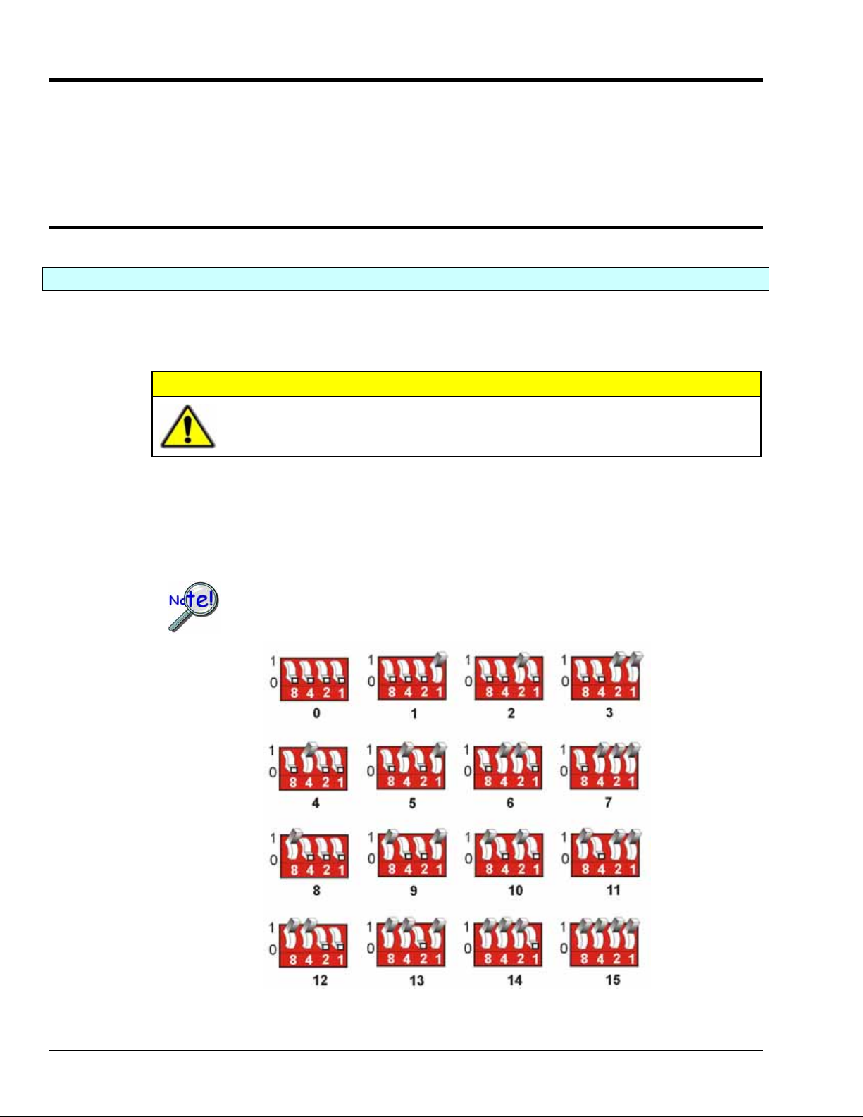
To assign a channel address to the DBK85 module, first locate the DIP switch on the right side of the rear
panel. Four micro-switches [on the DIP switch] are used to set the module’s channel address in binary.
After ensuring that the system power is OFF, adjust the micro-switches to set the desired address. The 16
possible addresses are illustrated in the following figure.
Each module in the system must have a unique primary device channel address.
The 16 Possible Address Settings for DBK85 Modules
DBK85 pg. 2 988793 DBK Option Cards and Modules
Page 3

Configuring the Primary Data Acquisition Device
DaqBook/100 Series & /200 Series and DaqBoard [ISA type] Configuration
Use of a DBK85 with a DaqBook/100 Series, /200 Series devices, or with an ISA-type DaqBoard requires
the configuration of jumpers JP1 and JP4. These jumpers are located on the DaqBook/100 Series, /200
Series devices, and DaqBoard [ISA type] board.
1. If not using auxiliary power, set the JP1 jumper for Analog Option Card Use,
also referred to as the expanded analog mode.
Note:
These jumpers do not
apply to /2000 Series
Devices.
2. For DaqBook/100, DaqBook /112, and DaqBook /120 only, place the JP4 jumper in the single-ended
DaqBook/2000 Series & DaqBoard/2000 Series
No jumper configurations are required on the DaqBook/2000 series and DaqBoard/2000 series devices in
regard to connecting a DBK85.
mode.
Required Jumper Settings in DaqBook/100 Series & /200 Series
and ISA-Type DaqBoards
The JP1 default position (above) is necessary to power the interface circuitry of the
DBK85 via the internal ±15 VDC power supply. If using auxiliary power (e.g.,
DBK32A or DBK33) you must remove both JP1 jumpers.
For additional information refer to Power Requirements in the DBK Basics section and
to the DBK32A and DBK33 sections, as applicable.
Reference Note: Analog expansion cards convert all input signals to single-ended
voltages that are referenced to analog common. The DBK85’s analog common connector
is located next to the channel 1 BNC. The connector is typically used to provide a ground
reference point for differential measurements as discussed in Chapter 1, Signal
Management.
LogBooks
No jumper configurations are required on LogBook devices in regard to connecting a DBK85.
DBK Option Cards and Modules 988793 DBK85 pg. 3
Page 4

CE Compliance
If your data acquisition system needs to comply with CE standards, the DBK85 must be connected to the
LogBook or Daq device by a CA-143-x cable. In addition, the CE compliant operating conditions must be
met as specified on the DBK85 module’s Declaration of Conformity card, which is shipped with the
module.
Reference Notes: If your data acquisition system needs to comply with CE standards,
refer to the following:
o the DBK85’s Declaration of Conformity
o the CE Compliance section of Signal Management chapter of this manual
Connecting the DBK85 to Signals and to the Primary Data Acquisition Device
You can connect the DBK85 module to your primary data acquisition device and to its signal inputs after
you have completed the following:
• set the DBK85 module’s address
• configured the primary data acquisition device, if applicable
You can connect up to 16 signal lines to one DBK85, i.e., one per BNC. These inputs accept voltages up
to ±10 VDC.
Connect the DBK85 module as follows. Note that if your system needs to be CE Compliant, be sure to
read the preceding CE Compliance section prior to connecting the DBK85.
1. Connect each signal input line’s BNC connector to a mating connector on the module. Overlays for
CH0 to CH15 identify the associated BNC. Remember, signal input is limited to ±10 VDC.
Tip: Label each signal input line with its associated channel information.
2. For a single DBK85 module, connect one end of the P1 cable to the module’s male DB37 output
connector.
For DaqBook applications - use a CA-37-x cable.* •
• • For DaqBoard/2000 Series or /2000c Series boards - use a CA-37-x with a DBK200 Series
adapter.*
For DaqBoard [ISA type] boards - use a CA-131-x cable.*
* CA-37-x and CA-131-x cables do not meet CE compliance requirements. Refer to the
preceding CE section if CE compliance must be met.
3. Connect the free end of the cable to the P1 port of the LogBook or Daq device. For multiple DBK85
modules, use a CA-37-x (or CA-131-x) cable to daisy-chain several modules or an expansion
module. For example, three DBK85s could be connected to a LogBook or a Daq device via a CA37-3 cable.
Note: For longer cable runs you can use a CA-113 cable to add 6 ft of length.
DBK85 pg. 4 988793 DBK Option Cards and Modules
Page 5

Analog Common
DBK85’s analog common connector is located just left of the channel 1 BNC. The connector is typically
used to provide a ground reference point for differential measurements as discussed in the Signal
Management section of Chapter 1.
Software Setup
The DBK85 has no special software settings. The software controls are equivalent to those for a direct
connection; e.g., for a DaqBoard/2000 Series board there are Type selections of x1 to x64, representing the
internal gain of that board. When using the DBK8 5 with that board you will have the same Type options
since the DBK85 has a fixed gain of x1.
LogView does not include the means to directly select a DBK85. To use a DBK85 with
LogBook, select DBK80. This will recognize the DBK85, but will identify it as a
DBK80.
Reference Notes:
o DaqView users - Refer to Chapter 3, DBK Setup in DaqView.
o LogView users - Refer to Chapter 4, DBK Setup in LogView. See above note.
DBK Option Cards and Modules 988793 DBK85 pg. 5
Page 6

Specifications – DBK85
Connectors:
DBK37 male connector designated as P1. Connects to P1 on a DaqBook, DaqBoard, or LogBook via a CA-37-x
or a CA-131-x cable.
BNC: 16 BNC connectors (CH0 through CH15) for signal connection.
Analog Common: Binding Post/Banana Jack. Provides a ground reference point for differential measurements.
Gain Ranges: fixed gain at x1
Inputs: 16 differential voltage inputs
Maximum Voltage Range: ±10 VDC
Input Impedance: 20M Ohm
Accuracy: ±[0.025% +150 µV] (typ), ±[0.1% +250 µV] (max)
Noise: 60 µVrms (typ)
Maximum Input Voltage (without damage): ±25 V
3 dB Bandwidth: 2.6 MHz
CMRR: 80 dB typ
Power: 25 mA max from ±15 VDC
A Note Regarding Source Impedance and Settling Time
High speed multiplexing of signal sources with non-zero impedance will result in reading errors caused by settling
time. In the simplest form, a multiplexing system consists of a group of switches, with internal resistance, and an
output capacitance at the input of an amplifier feeding an A/D converter with a sample-hold circuit on the input.
During the short time a channel signal is connected to the A/D amplifier, the signal must charge the output
capacitance to the true value of the signal so that the sample-hold captures an accurate value for the A/D converter
to digitize. If the source has significant internal impedance the voltage reading will be reduced.
Source impedance below 1000 ohms will create negligible error. Above 1000 ohms, the effects are increasingly
noticeable. An accurate source in series with a variable resistance will readily demonstrate this. Although the
effect is exponential, an easy reference point to remember is that 25K of source impedance will result in
approximately a 10% error.
Reading Error vs. Source Resistance
DBK85 pg. 6 988793 DBK Option Cards and Modules
 Loading...