

Page 1
DBK84 14-Channel Thermocouple Module
Overview …… 1
Hardware Setup …… 2
Module Connection …… 2
Open Thermocouple Detection …… 3
Module Configuration …… 4
DaqBook/100 Series & /200 Series and DaqBoard [ISA type] Configuration …… 5
DaqBook/2000 Series and DaqBoard/2000 Series Configuration …… 5
Software Setup …… 6
Using a Temperature Calibrator …… 7
DBK84 – Specifications …… 8
Reference Notes:
o Chapter 2 includes pinouts for P1, P2, P3, and P4. Refer to pinouts applicable to
your system, as needed.
o In regard to calculating system power requirements, refer to DBK Basics located near
the front of this manual.
Overview
The DBK84 is used in temperature measurement applications and provides connections for 14
thermocouples through convenient mini-TC connectors.
The DBK84 features on-board cold junction compensation (CJC) for direct measurement of type J, K, T, E,
N28, N14, S, R, and B thermocouples. The following table provides the temperature range for each of
these thermocouple types.
Thermocouple Temperature Ranges
T/C Type J K T E N28 N14 S R B
Temperature
Range °C
Temperature
Range °F
-200 to
760
-328 to
1400
-200 to
1200
-328 to
2192
-200 to
400
-328 to
752
-270 to
650
-454 to
1202
-270 to
400
-454 to
752
0 to
1300
32 to
2372
-50 to
1768
-58 to
3214
-50 to
1768
-58 to
3214
50 to
1780
122 to
3236
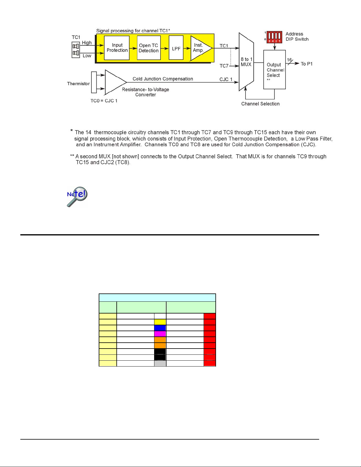
Up to fourteen external thermocouples can be connected to the DBK84 module. Channels 1 through 7 are
used for the first seven thermocouples, and channels 9 through 15 are used for the second set of seven.
Note: DBK84 has two on-board CJCs. They are measured on channels 0 and 8.
In addition to thermocouple measurements, each input channel can be configured for a fixed voltage gain
of 100. When in this mode, voltage can be measured in the range of ±100 mV, or ±50 mV, depending on
the type of Daq device being used.
Up to sixteen DBK84 modules can be attached to a single LogBook or Daq device, providing up to 224
temperature channels.
DBK Option Cards and Module 989494 DBK84 pg. 1
Page 2
Hardware Setup
Module Connection
The DBK84 accepts up to 14 mini-TC plugs in its channels 1 through 7 and 9 through 15. All channels
have the same level of functionality.
Thermocouple wire is standardized, color-coded, and polarized, as noted in the following table.
In comparison to typical DBK options, the DBK84 demands significant power from the
system’s ±15 V power supplies. It is important that you calculate your system’s power
demand, as you may need to add auxiliary power supplies. For additional information
refer to Power Requirements in the DBK Basics section.
Thermocouple Standards
T/C
Type
J White Red
K Yellow Red
T Blue Red
E Violet Red
N28 Orange Red
N14 Orange Red
S Black Red
R Black Red
B Gray Red
(+) Lead to
Channel High
(-) Lead to
Channel Low
Mini-TC plugs are type-specific, and for best measurement operation the plug TC type should match the
wire TC type. If necessary, copper/copper (Type U) plugs may be used, but measurement stability will be
slightly degraded. Mini-TC plugs are polarized as well, and it is critical for proper measurement operation
that this polarity be followed when connecting the thermocouple wire. Once wired, the TC plugs will only
mate into the DBK84’s connectors in one orientation, ensuring a correct connection.
It should be noted that thermocouples output very small voltages and that long thermocouple leads can
pickup a large amount of noise. However, the DBK84 inherently provides a high level of noise immunity
via its 4 Hz signal bandwidth and input filtering. If desired, further noise reduction can be achieved
pg. 2, DBK84 989494 DBK Option Cards and Modules
Page 3
through the use of shielded thermocouples and/or averaging.
You can minimize the effect of noise by (1) using shielded thermocouples,
(2) averaging readings, or (3) employing both of these practices.
To accommodate shielding, grounded connections, labeled “Analog Common,” are provided. A typical
use of the connection would be to attach the shield of a shielded thermocouple.
If a thermocouple shield is connected to the DBK84 module, leave the shield
unconnected at the other end of the thermocouple.
Open Thermocouple Detection
The DBK84 is equipped with open thermocouple detection for each channel. This means that a broken
thermocouple wire [or otherwise unconnected input] that is measured will result in an off-scale reading.
This is accomplished by applying a small bias current to each of the channel inputs. Whenever a valid
input is absent, the bias current saturates the input amplifier, resulting in the off-scale reading. When in
this
“off-scale” state, however, the input amplifier draws more current from the power supply. Specifically, the
power draw of the module from ±15 V will increase by 0.75 mA for each open channel.
If available power is limited, insert shorted TC plugs into unused channels. This will
minimize power consumption. Note that it is not enough to simply avoid scanning unused
channels; to minimize power consumption the channels must be physically shorted in the
hardware.
The power requirements, detailed in the product specification, assume worst case
connection conditions.
DBK Option Cards and Module 989494 DBK84 pg. 3
Page 4

Module Configuration
Up to sixteen DBK84 modules can be attached to a single LogBook or Daq device. Since multiple
modules are connected via a parallel interface, each must have a unique channel address.
To assign a channel address to the DBK84 module, first locate the DIP switch on the front panel (next to
P1). Four micro-switches [on the DIP switch] are used to set the module’s channel address in binary.
After ensuring that the system power is OFF, adjust the micro-switches to set the desired address.
CAUTION
Adjustment of the channel address must only be performed when the system
power is OFF. Failure to do so may result in equipment damage.
Each module in the system must have a unique address.
DBK84 Channel Address Settings
pg. 4, DBK84 989494 DBK Option Cards and Modules
Page 5

DaqBook/100 Series & /200 Series and DaqBoard [ISA type] Configuration
Use of a DBK84 with a DaqBook/100 Series device, DaqBook/200 Series device, or with an ISA-type
DaqBoard requires the configuration of jumpers JP1 and JP4 located on the DaqBook or DaqBoard device.
1. If not using auxiliary power, set the JP1 jumper for Analog Option Card Use,
also referred to as the expanded analog mode.
Note:
These jumpers do not
apply to /2000 Series
devices.
Required Jumper Settings in DaqBook/100 Series Devices,
DaqBook/200 Series Devices, and ISA-Type DaqBoards
The JP1 default position (above) is necessary to power the interface circuitry of the
DBK84 module via the internal ±15 VDC power supply. If using auxiliary power
(e.g., a DBK32A or DBK33), you must remove both JP1 jumpers. Refer to Power
Requirements in the DBK Basics section and to the DBK32A or DBK33 sections as
applicable.
2. For DaqBook/100, DaqBook /112, and DaqBook /120 only, place the JP4 jumper in the single-ended
mode.
Note: Analog expansion options convert all input signals to single-ended voltages that are referenced to
analog common.
DaqBook/2000 Series and DaqBoard/2000 Series Configuration
No jumper configurations are required for the /2000 series devices.
DBK Option Cards and Module 989494 DBK84 pg. 5
Page 6

Software Setup
Note: LogView and DaqView software each include functions for the conversion and linearization of
When a DBK84 is selected in DaqView or LogView, thermocouple types must also be selected for the
module’s channels. The two programs each use a different method for selecting the thermocouple types.
In LogView …
In LogView, the LogBook Hardware Configuration Window is used to select the thermocouple types.
After selecting DBK84, set each of the module’s channels according to the actual thermocouple being used
for the channel’s input.
In the following screen-shot [from LogView], we see a J-type thermocouple being selected for Channel 1
of a DBK84.
Reference Notes:
o DaqView users - Refer to Chapter 3, DBK Setup in DaqView.
o LogView users - Refer to Chapter 4, DBK Setup in LogView.
o Programmers using Daq devices should refer to related sections in the Programmer’s
Manual.
thermocouple readings into temperature data.
LogBook Hardware Configuration Window
In DaqView ….
In DaqView, after selecting the DBK84 in the Configure System Hardware Window, the Channel Setup
Tab (on the main window) is used to select the thermocouple types (see following figure). The channel
types can be changed by double-clicking in the Types column, or by using the Channel Type pull-down list.
In the following screen-shot [from DaqView], we see a J-type thermocouple being selected for a DBK84
module’s Channel 1. Note that the channel is designated “P1 0-1” in the Channel column.
DaqView, Channel Setup
pg. 6, DBK84 989494 DBK Option Cards and Modules
Page 7

Using a Temperature Calibrator
The DBK84 thermocouple module provides accurate and repeatable temperature measurements across a
wide range of operating conditions. However, all instrumentation is subject to drift with time and with
ambient temperature change. If the ambient temperature of the operating environment is below 18°C or
above 28°C, or if the product is near or outside its one-year calibration interval, then the absolute accuracy
may be improved through the use of an external temperature calibrator.
A temperature calibrator is a temperature simulation instrument that allows selection of thermocouple type
and temperature. For proper operation, it must be connected to the DBK84 with the same type
thermocouple wire and connector that is used in normal testing. The calibrator then generates and supplies
a voltage to the module. The supplied voltage corresponds to that which would be generated by the chosen
thermocouple type at the selected temperature.
The temperature selected on the calibrator will be dictated by the nature of no rmal testing. 0°C is usually
the best choice. Calibrators are the most accurate at this setting, and the connecting thermocouple wire will
contribute very little error at this temperature. However, if the dynamic range of the normal testing is, for
example, 100°C to 300°C, a selection of 200°C may give better results. In either case, the level of
adjustment is determined by comparing the unit reading to the selected calibrator temperature. For
example, if the calibrator is set to 0°C output, and the DBK unit reads 0.3°C, then an adjustment of –0.3°C
is required. That is, the adjustment value is determined by subtracting the DBK reading from the calibrator
setting.
To implement the adjustment in DaqView:
1. Ensure that the acquisition process is turned off.
2. Click on the cell in the Units column for the channel that is connected to the calibrator. The
engineering units pull-down menu above the grid becomes active.
3. Click on the down arrow and select the “mx+b” option. This option allows post-acquisition
mathematical manipulation.
4. For the example adjustment, enter -0.3 for “b.” The channel under calibration will now
read 0°C.
Note that this adjustment is a mathematical operation only, and in no way alters the hardware
calibration of the product. Moreover, it operates on a per channel basis, with the settings for a
given channel having no influence on any other channels.
To implement the adjustment in LogView:
1. Ensure that the acquisition process is turned off.
2. In the Analog Input Channel Configuration window, select the “User Scaling” tab.
3. Click on the “Offset” cell for the channel that is connected to the calibrator.
4. For the example adjustment, enter -0.3 for “Offset.” The channel under calibration will now
read 0°C.
Note that this adjustment is a mathematical operation only, and in no way alters the hardware
calibration of the product. Moreover, it operates on a per channel basis, with the settings for a
given channel having no influence on any other channels.
DBK Option Cards and Module 989494 DBK84 pg. 7
Page 8
DBK84 - Specifications
Name/Function:
DBK84 – 14 Channel High-Accuracy Thermocouple Module
System Connector: All DBK options have a DB37 male, which mates with P1 on the DaqBoard, DaqBook,
TC/mV Connector: Mini-TC connectors
Functions: TC types J, K, S, T, E, B, R, N; x100 (voltage)
Inputs: 14 differential TC/mV inputs
Input Voltage Range: ±100 mV with a DaqBoard/2000 or LogBook
Input Impedance: 40M Ohm (differential); 20M Ohm (single-ended)
Input Bandwidth: 4 Hz
Input Bias Current: 10 nA typ
CMRR: 100dB typ
Maximum Working Voltage (signal + common mode): ±10 V
Over-Voltage Protection: ±40 V
Power Requirements: 60 mA max from ±15V; 2 mA max from +5 V
Operating Temperature: 0°C to 50°C
Voltage Accuracy: ±(0.2% of reading +50 µV)
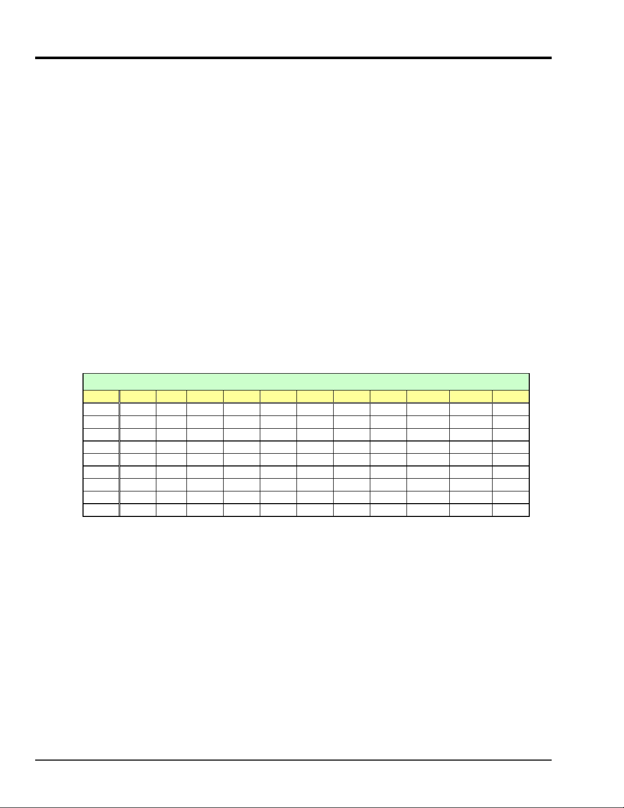
TC Accuracy: See table and accuracy conditions. Valid for one year, 18 to 28°C
Minimum Resolution: 0.1°C for all TC types
LogBook, or other DBK options
±50 mV with a DaqBook or DaqBoard
TC Accuracy at Measurement Temperature in °C (±°C)
Type Min Max -100 0 100 300 500 700 900 1100 1400
J
K
T
E
S
R
B
N28
N14
-200 760 0.8 0.7 0.7 0.8 0.9 0.9 — — —
-200 1200 0.9 0.8 0.8 0.9 1.1 1.1 1.2 1.3 —
-200 400 0.9 0.8 0.8 0.8 — — — — —
-270 650 0.8 0.7 0.7 0.7 0.8 — — — —
-50 1768 — 3.1 2.4 2.0 2.0 1.9 2.0 2.1 2.1
-50 1768 — 3.1 2.1 2.0 1.9 1.9 1.7 1.9 2.0
50 1780 — — — 4.9 3.2 2.8 2.4 2.3 2.0
-270 400 1.2 0.9 0.9 0.9 — — — — —
0 1300 — 0.9 0.9 0.9 1.1 1.1 1.2 1.3 —
Accuracy conditions:
• Exclusive of thermocouple errors
• Exclusive of noise
• V
CM
= 0
Accuracy at Measurement Temperature in ˚C (±˚C)
pg. 8, DBK84 989494 DBK Option Cards and Modules
 Loading...