

Page 1
DBK81, DBK82, and DBK83 Thermocouple Cards
Overview …… 1
Hardware Setup …… 2
Software Setup …… 7
Using a Temperature Calibrator …… 8
DBK81, DBK82, DBK83 – Specifications …… 9
Overview
DBK81 – 7 Channel Card
DBK82 – 14 Channel Card
Card Connection …… 2
Open Thermocouple Detection …… 3
Installing the DBK82 in the DBK41 Enclosure ……3
Using the Connection POD, DBK83 Only…… 4
POD-1 Dimensions ….. 5
Card Configuration …… 6
DaqBook/100 Series & /200 Series and DaqBoard [ISA type] Configuration …… 6
DaqBook/2000 Series and DaqBoard/2000 Series Configuration …… 6
Reference Notes:
o Chapter 2 includes pinouts for P1, P2, P3, and P4. Refer to pinouts applicable to
your system, as needed.
o In regard to calculating system power requirements, refer to DBK Basics located
near the front of this manual.
The DBK81, DBK82, and DBK83 are used in temperature measurement applications that make use of
thermocouples. The DBK81 provides connections for 7 thermocouples. Both the DBK82 and the DBK83
provide connections for 14 thermocouples. The two 14 channel cards differ from each other in that the
input connectors of the DBK82 are on the board, but connectors of the DBK83 are located in an external
connection pod.
DBK83 – 14 Channel Card with
External Connection Pod
All three cards feature on-board cold junction compensation (CJC) for direct measurement of type J, K, T,
E, N28, N14, S, R, and B thermocouples. The following table provides the temperature range for each of
these thermocouple types.
Thermocouple Temperature Ranges
T/C Type J K T E N28 N14 S R B
Temperature
Range °C
Temperature
Range °F
-200 to
760
-328 to
1400
-200 to
1200
-328 to
2192
-200 to
400
-328 to
752
-270 to
650
-454 to
1202
-270 to
400
-454 to
752
0 to
1300
32 to
2372
-50 to
1768
-58 to
3214
-50 to
1768
-58 to
3214
50 to
1780
122 to
3236
The three DBK cards connect to external thermocouples via channels, as follows:
• DBK81 – up to seven thermocouples can be connected, using channels 1 through 7, inclusive
• DBK82 and DBK83 - up to fourteen thermocouples can be connected, using channels
1 through 7 for the first seven and channels 9 through 15 for the second set of seven.
Note: On the DBK81, there is one CJC. It is measured on channel 0. On the DBK82 and DBK83 there
are two CJCs, measured on channels 0 and 8.
In addition to thermocouple measurements, each input channel can be configured for a fixed voltage gain
of 100. When in this mode, voltage can be measured in the range of ±100 mV, or ±50 mV, depending on
the type of Daq device being used.
Up to sixteen DBK81, DBK82, or DBK83 cards can be attached to a single LogBook or Daq device,
providing up to 224 temperature channels. The cards need not be the same. For example, you could have
ten DBK81 cards, three DBK82 cards, and three DBK83 cards in one system.
DBK Option Cards and Modules 989494 DBK81, DBK82, and DBK83 pg. 1
Page 2
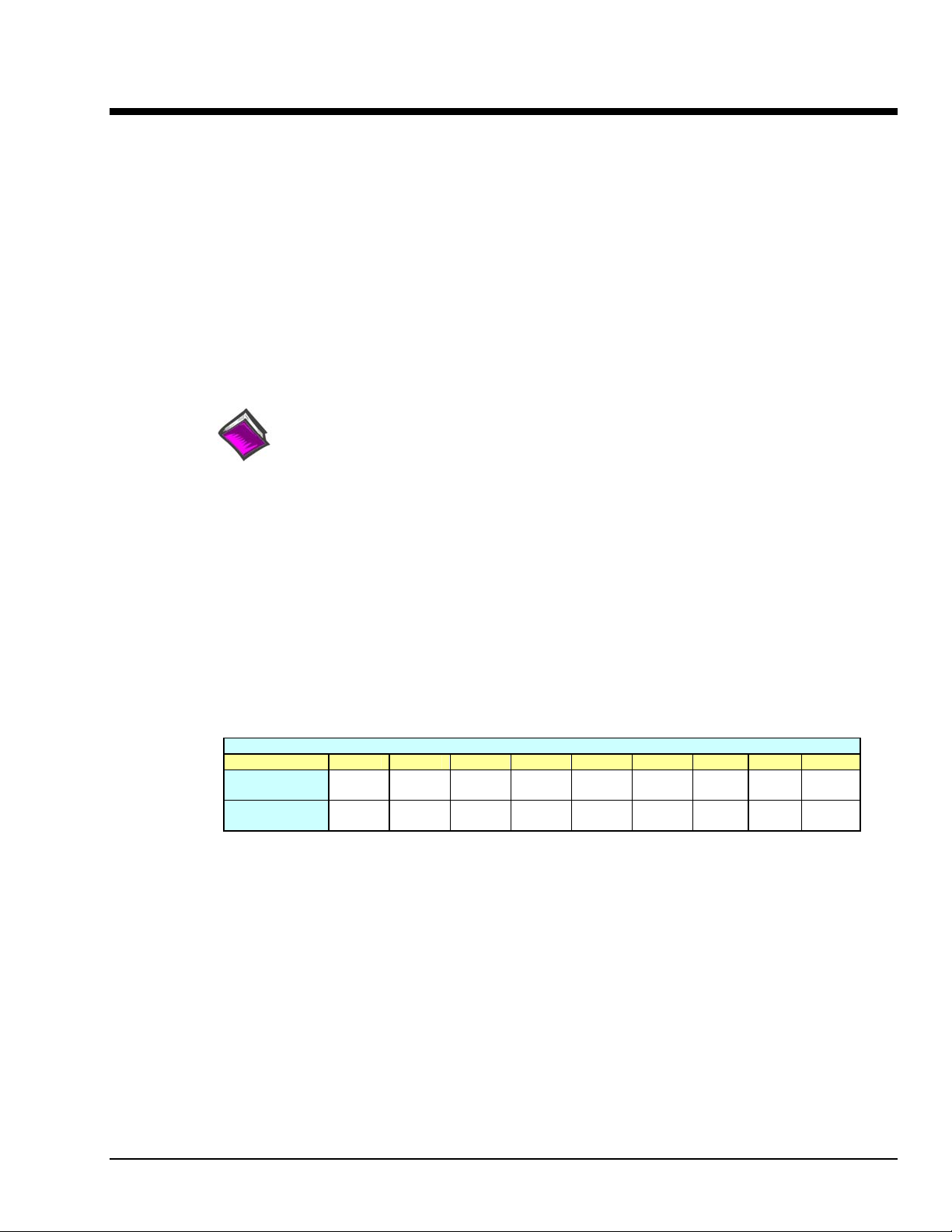
*The DBK81 block diagram can be applied to the DBK82 and DBK83, as their diagrams only differ to the
one above in regard to the number of input channels provided.
Hardware Setup
Card Connection
Connect the thermocouple wires to the intended input terminals on the card. The DBK81 provides input
connections for channels 1 through 7, while the DBK82 and DBK83 offer input connections for channels
1 through 7 and 9 through 15. All channels have the same level of functionality.
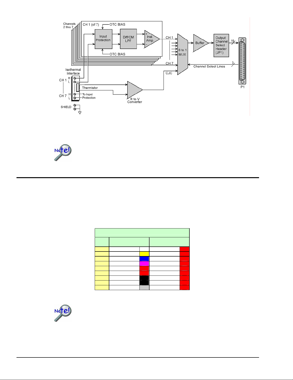
Thermocouple wire is standardized, color-coded, and polarized, as noted in the following table.
DBK81 Block Diagram*
In comparison to other DBK cards, the DBK81, DBK82, and DBK83 demand significant
power from the system’s ±15V power supplies. It is important that you calculate your
system’s power demand, as you may need to add auxiliary power supplies.
Refer to Power Requirements in the DBK Basics section for additional information.
Thermocouple Standards
T/C
Type
J White Red
K Yellow Red
T Blue Red
E Violet Red
N28 Orange Red
N14 Orange Red
S Black Red
R Black Red
B Gray Red
(+) Lead to
Channel High
(-) Lead to
Channel Low
Input connections for the three cards are labeled “H” and “L” to denote polarity.
For isothermal performance, an exposed, grounded copper plane surrounds the input
connectors. It is important that non-insulated input wires do not contact the grounded
plane − since such contact can degrade measurement integrity.
pg. 2, DBK81, DBK82, & DBK83 989494 DBK Option Cards and Modules
Page 3
It should be noted that thermocouples output very small voltages and that long thermocouple leads can
pickup a large amount of noise. However, the DBK81, DBK82, and DBK83 inherently provide a high
level of noise immunity via their 4 Hz signal bandwidth and input filtering. If desired, further noise
reduction can be achieved through the use of shielded thermocouples and/or averaging.
You can minimize the effect of noise by (1) using shielded thermocouples,
(2) averaging readings, or (3) employing both of these practices.
To accommodate shielding, grounded connections, labeled “SHIELD,” are provided. A typical use of the
connection would be the attachment of the shield to a shielded thermocouple.
If a thermocouple shield is connected on the DBK card, leave the shield
unconnected at the other end of the thermocouple.
Open Thermocouple Detection
The DBK81, DBK82, and DBK83 are equipped with open thermocouple detection for each channel. This
means that a broken thermocouple wire [or otherwise unconnected input] that is measured will result in an
off-scale reading. This is accomplished by applying a small bias current to each of the channel inputs.
Whenever a valid input is absent, the bias current saturates the input amplifier, resulting in the off-scale
reading. When in this “off-scale” state, however, the input amplifier draws more current from the power
supply. Specifically, the power draw of a card from ±15 V will increase by 0.75 mA for each open
channel.
If available power is limited, short unused channels by connecting a short length of wire
between the H and L terminals. This will minimize power consumption. Note that it is not
enough to simply avoid scanning unused channels; to minimize power consumption the
channels must be physically shorted in the hardware.
The power requirements, detailed in the product specification, assume worst case
connection conditions.
Installing the DBK82 in the DBK41 Enclosure
Because of its physical size, the DBK82 will not fit into 1-slot enclosures such as the DBK10 or
DaqBook/216. It does fit, however, in the DBK41 enclosure, and in “drawer-type” products, such as the
DaqBook/260.
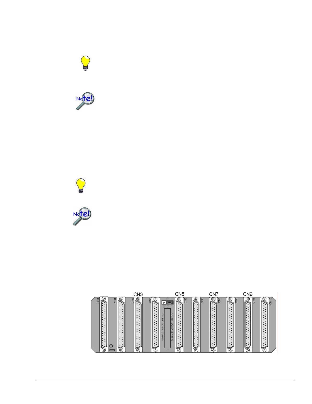
Installation of the DBK82 is possible in DBK41 connectors CN3, CN5, CN7, and CN9. The connector
labels are visible near the upper edge of the DBK41’s printed circuit board, as indicated in the following
figure.
DBK41’s Printed Circuit Board
DBK82 cards can be connected to CN3, CN5, CN7, and CN9.
DBK Option Cards and Modules 989494 DBK81, DBK82, and DBK83 pg. 3
Page 4
Using the Connection POD, DBK83 Only
Unlike other DBK units, the input connections for the DBK83 do not exist on the card itself. Instead, they
exist in an external connection pod, POD-1. POD-1 simply represents a physical relocation of the input
screw terminals and cold junction sensors that reside on the card in the case of the DBK81 and DBK82.
POD-1 connects to the DBK83 unit via the CA-239 cable. POD-1 dimensions are provided at the end of
this section.
The female-end of the CA-239
cable connects to POD-1’s
male 44-pin connector.
You must remove the four cover screws
and the cover plate to access the pod’s
terminal blocks. The terminal block
layout is provided in the following
figure.
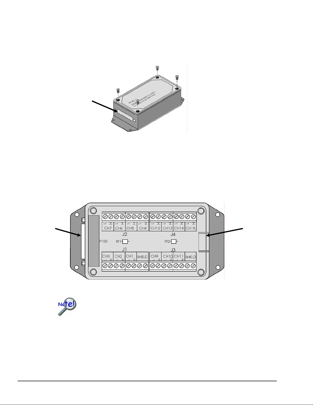
POD-1
To install thermocouple wires in POD-1:
1. Remove the four screws of the POD-1 cover.
2. Route the thermocouple wires through the input hole of the POD-1 and connect them to the
intended channels. Note the “H” and “L” polarity designations on the channels for proper
connection. (See the following figure).
3. Replace the POD-1 cover and secure it with the four screws that were removed in step 1.
The CA-239
cable connects
here.
Thermocouple wires route
through this opening.
POD-1 Connection Terminals
For isothermal performance, an exposed, grounded copper plane surrounds the input
connectors. It is important that non-insulated input wires do not contact the grounded
plane − since such contact can degrade measurement integrity.
pg. 4, DBK81, DBK82, & DBK83 989494 DBK Option Cards and Modules
Page 5
To connect the POD-1 to the DBK83:
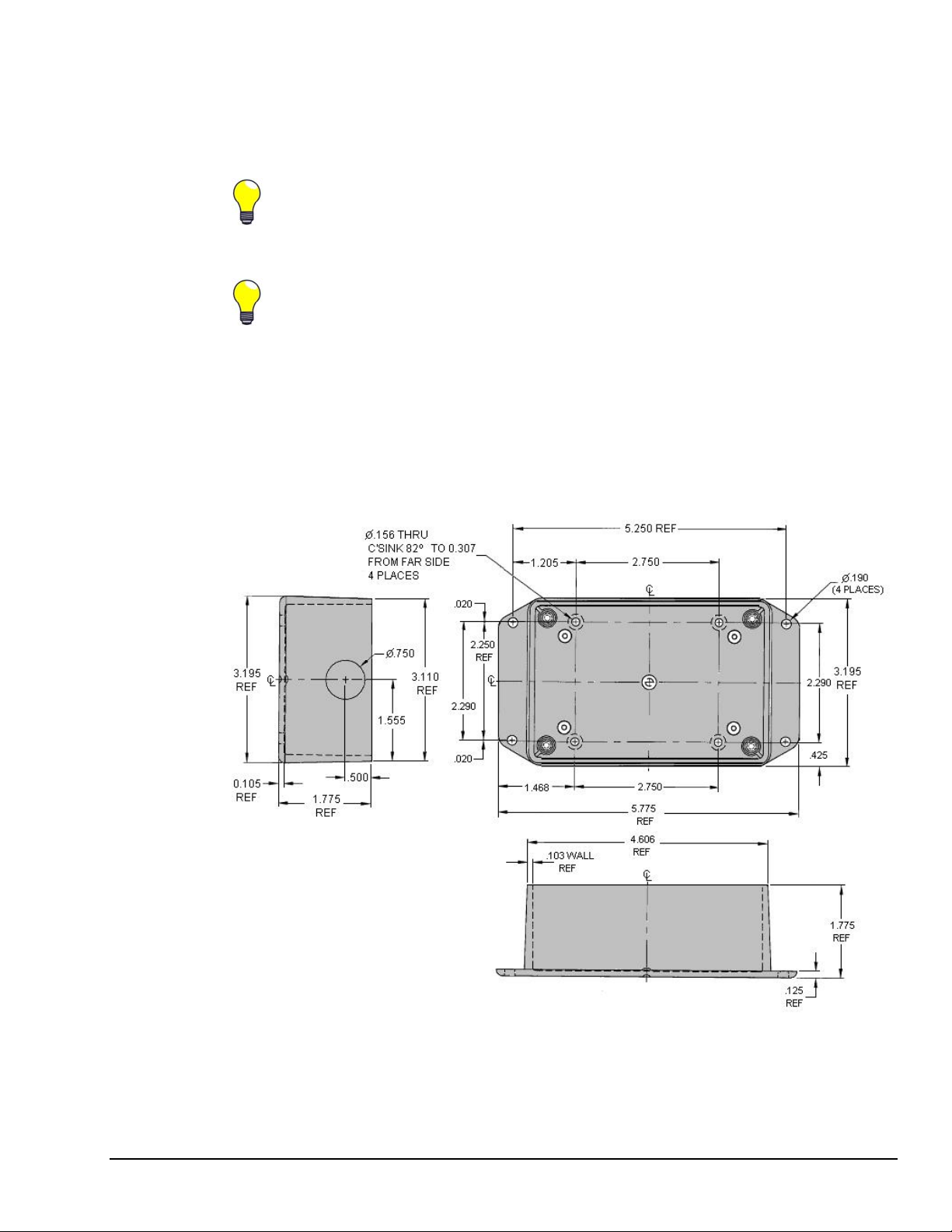
POD-1 Dimensions
1. Connect the male end of the CA-239 cable to the female 44-pin connector on the DBK83.
2. Connect the female end of the CA-239 cable to the male 44-pin connector on the POD-1.
The system design of the DBK83 allows for the quick connection/disconnection of up to 14
thermocouples at one time. You may find it advantageous to have several POD-1 modules
permanently wired to different sets of thermocouples and to simply swap the CA-239 cable
between them and one DBK83 card, as desired.
Because of the opposing gender on the CA-239 cable ends, it is possible to mate multiple
CA-239 cables together to increase the distance from the POD-1 to the DBK83. Because of
characteristics of the cable design and the signals on it, measurement integrity is not
affected by doing so, and there are no practical limits on how many cables can be used.
POD-1 Dimensions. POD-1 is for use with DBK43.
DBK Option Cards and Modules 989494 DBK81, DBK82, and DBK83 pg. 5
Page 6
Card Configuration
Up to sixteen DBK81, DBK82, or DBK83 cards can be attached to a single LogBook or
Daq device, providing up to 224 temperature channels. The cards need not be the same.
For example, you could have ten DBK81 cards, three DBK82 cards, and three DBK83 cards
in one system.
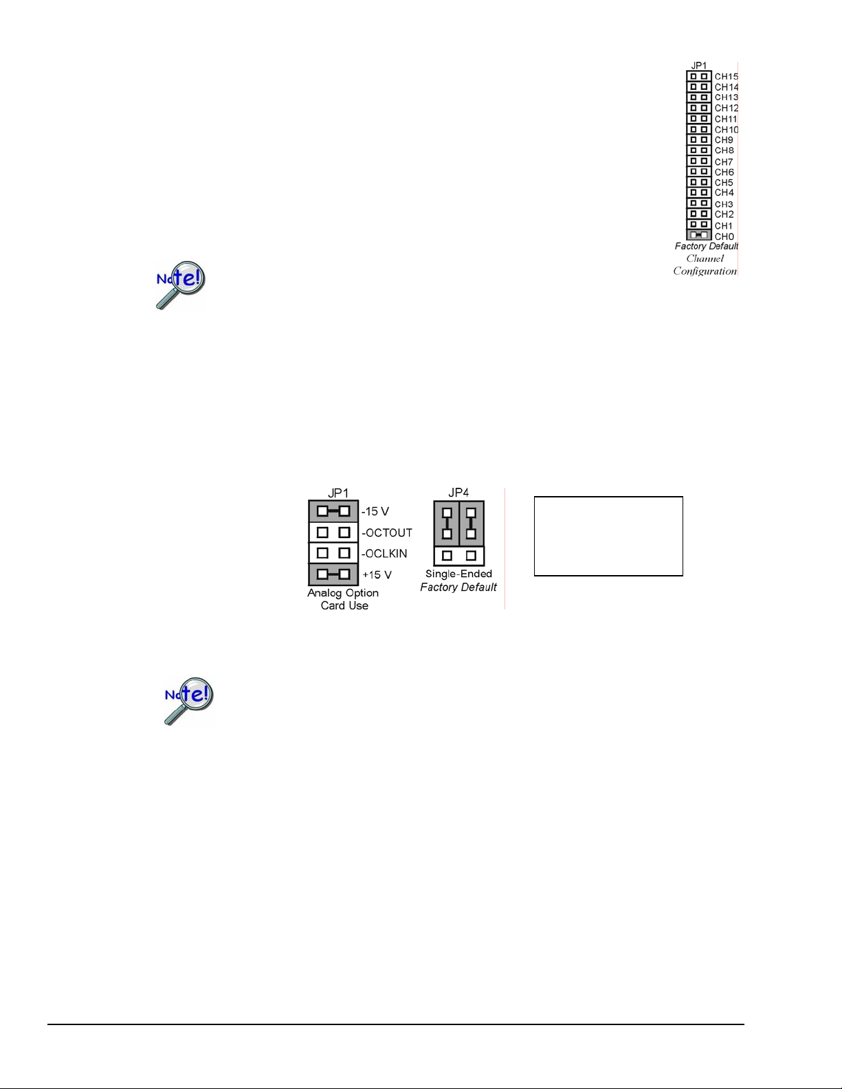
Since multiple cards are connected via a parallel interface, each card must have a unique
channel address. To assign a channel number to the card, locate the 16×2-pin header
(labeled JP1). JP1’s jumper locations are labeled CH0 through CH15. Place the jumper on
the two pins that correspond with the intended channel.
Only one channel configuration jumper is to be used per card.
Each card in the system must have a unique jumper setting.
DaqBook/100 Series & /200 Series and DaqBoard [ISA type] Configuration
Use of a DBK81, DBK82, or DBK83 with a DaqBook/100 Series device, /200 Series device, or an
ISA-type DaqBoard, requires the configuration of jumpers JP1 and JP4 located on the DaqBook or
DaqBoard, as applicable.
1. If not using auxiliary power, set the JP1 jumper for Analog Option Card Use,
also referred to as the expanded analog mode.
Required Jumper Settings in DaqBook/100 Series &
2. For DaqBook/100, DaqBook /112, and DaqBook /120 only, place the JP4 jumper in the single-ended
mode.
Note: Analog expansion cards convert all input signals to single-ended voltages that are referenced to
analog common.
DaqBook/200 Series Devices and ISA-Type DaqBoards
The JP1 default position (above) is necessary to power the interface circuitry of the
DBK81, DBK82, and DBK83 cards via the internal ±15 VDC power supply. If using
auxiliary power (e.g., a DBK32A or DBK33), you must remove both JP1 jumpers.
Refer to Power Requirements in the DBK Basics section and to the DBK32A and
DBK33 sections as applicable.
DaqBook/2000 Series and DaqBoard/2000 Series Configuration
No jumper configurations are required for the /2000 series devices.
Note:
These jumpers do not
apply to /2000 Series
devices.
pg. 6, DBK81, DBK82, & DBK83 989494 DBK Option Cards and Modules
Page 7
Software Setup
Note: LogView and DaqView software each include functions for the conversion and linearization of
When a DBK81, DBK82, or DBK83 is selected in DaqView or LogView, thermocouple types must also be
selected for the card’s channels. The two programs each use a different method for selecting the
thermocouple types.
In LogView …
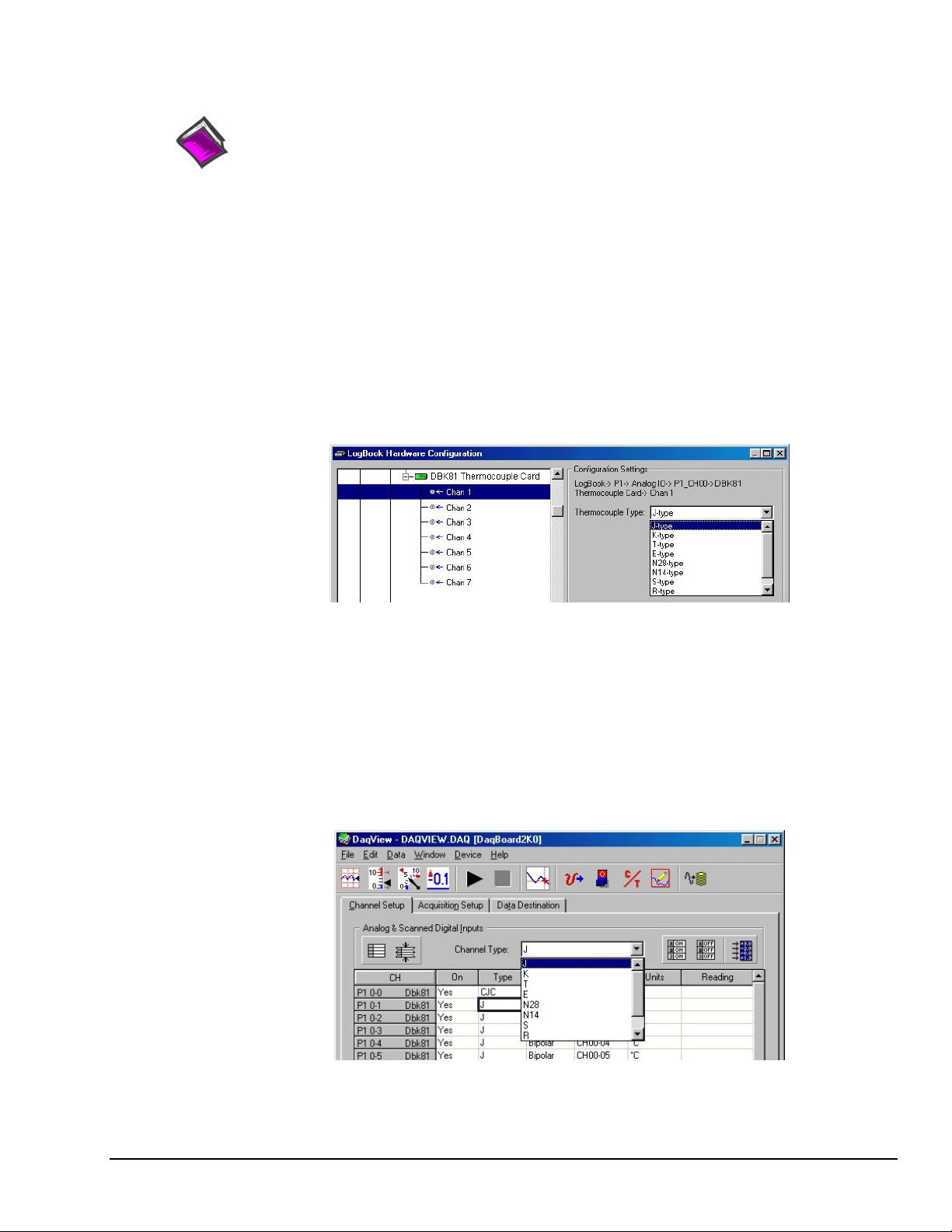
In LogView, the LogBook Hardware Configuration Window is used to select the thermocouple types.
After selecting DBK81, DBK82, or DBK83, set each of the card’s channels according to the actual
thermocouple being used for the channel’s input.
In the following screen-shot [from LogView], we see a J-type thermocouple being selected for Channel 1
of a DBK81.
Reference Notes:
o DaqView users - Refer to Chapter 3, DBK Setup in DaqView.
o LogView users - Refer to Chapter 4, DBK Setup in LogView.
o Programmers using Daq devices should refer to related sections in the Programmer’s Manual.
thermocouple readings into temperature data.
LogBook Hardware Configuration Window
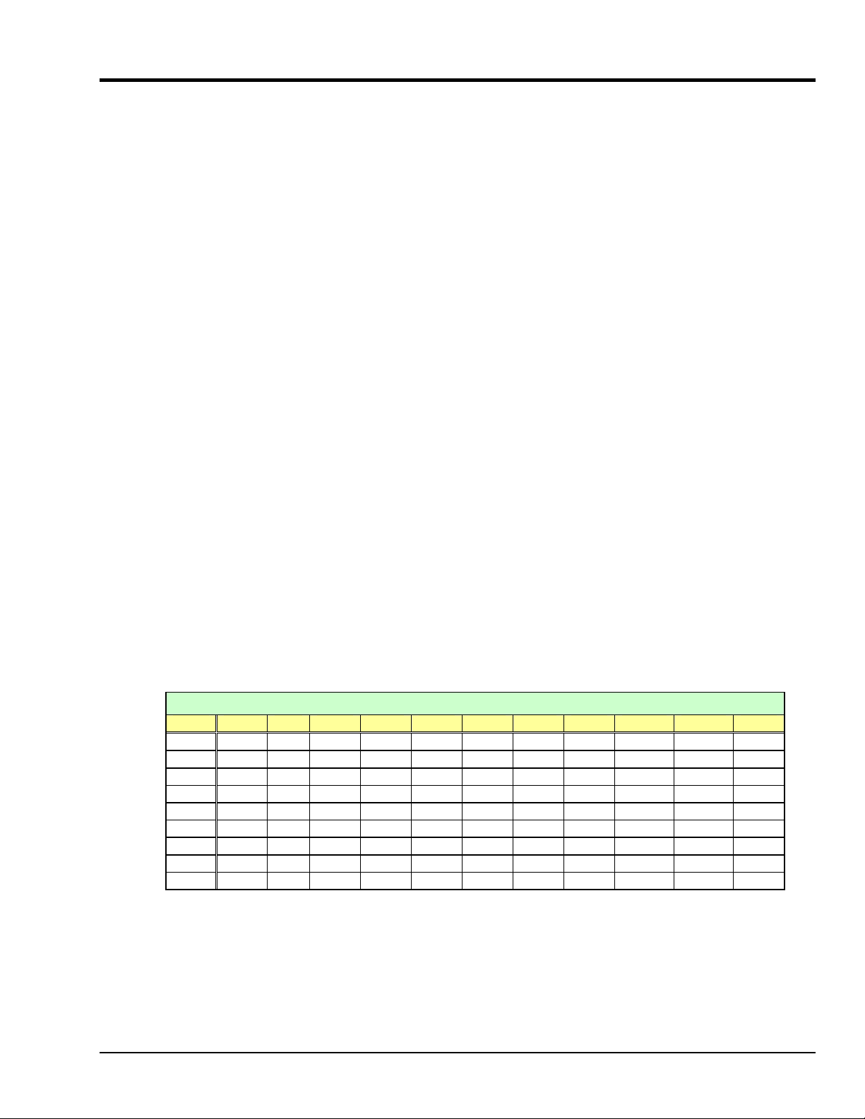
In DaqView ….
In DaqView, after selecting the DBK81, DBK82, or DBK83 in the Configure System Hardware Window,
the Channel Setup Tab (on the main window) is used to select the thermocouple types (see following
figure). The channel types can be changed by double-clicking in the Types column, or by using the
Channel Type pull-down list.
In the following screen-shot [from DaqView], we see a J-type thermocouple being selected for a DBK81
card’s Channel 1. Note that the channel is designated “P1 0-1” in the Channel column.
DaqView, Channel Setup
DBK Option Cards and Modules 989494 DBK81, DBK82, and DBK83 pg. 7
Page 8

Using a Temperature Calibrator
The DBK81, DBK82, and DBK83 thermocouple cards provide accurate and repeatable temperature
measurements across a wide range of operating conditions. However, all instrumentation is subject to drift
with time and with ambient temperature change. If the ambient temperature of the operating environment
is below 18°C or above 28°C, or if the product is near or outside its one-year calibration interval, then the
absolute accuracy may be improved through the use of an external temperature calibrator.
A temperature calibrator is a temperature simulation instrument that allows selection of thermocouple type
and temperature. For proper operation, it must be connected to the DBK81, DBK82, or DBK83 with the
same type thermocouple wire and connector that is used in normal testing. The calibrator then generates
and supplies a voltage to the card. The supplied voltage corresponds to that which would be generated by
the chosen thermocouple type at the selected temperature.
The temperature selected on the calibrator will be dictated by the nature of no rmal testing. 0°C is usually
the best choice. Calibrators are the most accurate at this setting, and the connecting thermocouple wire will
contribute very little error at this temperature. However, if the dynamic range of the normal testing is, for
example, 100°C to 300°C, a selection of 200°C may give better results. In either case, the level of
adjustment is determined by comparing the unit reading to the selected calibrator temperature. For
example, if the calibrator is set to 0°C output, and the DBK unit reads 0.3°C, then an adjustment of –0.3°C
is required. That is, the adjustment value is determined by subtracting the DBK reading from the calibrator
setting.
To implement the adjustment in DaqView:
1. Ensure that the acquisition process is turned off.
2. Click on the cell in the Units column for the channel that is connected to the calibrator. The
engineering units pull-down menu above the grid becomes active.
3. Click on the down arrow and select the “mx+b” option. This option allows post-acquisition
mathematical manipulation.
4. For the example adjustment, enter –0.3 for “b.” The channel under calibration will now
read 0°C.
Note that this adjustment is a mathematical operation only, and in no way alters the hardware
calibration of the product. Moreover, it operates on a per channel basis, with the settings for a
given channel having no influence on any other channels.
To implement the adjustment in LogView:
1. Ensure that the acquisition process is turned off.
2. In the Analog Input Channel Configuration window, select the “User Scaling” tab.
3. Click on the “Offset” cell for the channel that is connected to the calibrator.
4. For the example adjustment, enter -0.3 for “Offset.” The channel under calibration will now
read 0°C.
Note that this adjustment is a mathematical operation only, and in no way alters the hardware
calibration of the product. Moreover, it operates on a per channel basis, with the settings for a
given channel having no influence on any other channels.
pg. 8, DBK81, DBK82, & DBK83 989494 DBK Option Cards and Modules
Page 9
DBK81, DBK82, DBK83 - Specifications
Name/Function:
DBK81 – 7 Channel High-Accuracy Thermocouple Card
DBK82 – 14 Channel High-Accuracy Thermocouple Card
DBK83 – 14 Channel High-Accuracy Thermocouple Card with external TC/mV
screw-terminal connection pod
System Connector: All DBK options have a DB37 male, which mates with P1 on the DaqBoard, DaqBook,
LogBook, or other DBK options
TC/mV Connector
DBK81: Board-mounted screw terminals
DBK82: Board-mounted screw terminals
DBK83: External pod-mounted screw terminals
Functions: TC types J, K, S, T, E, B, R, N; x100 (voltage)
Inputs
DBK81: 7 differential TC/mV inputs
DBK82: 14 differential TC/mV inputs
DBK83: 14 differential TC/mV inputs
Input Voltage Range: ±100 mV with a DaqBoard/2000 or LogBook
±50 mV with a DaqBook or DaqBoard
Input Impedance: 40M Ohm (differential); 20M Ohm (single-ended)
Input Bandwidth: 4 Hz
Input Bias Current: 10 nA typ
CMRR: 100dB typ
Maximum Working Voltage (signal + common mode): ±10 V
Over-Voltage Protection: ±40 V
Power Requirements
DBK81: 35 mA max from ±15V; 2 mA max from +5 V
DBK82 and DBK83: 60 mA max from ±15V; 2 mA max from +5 V
Operating Temperature: 0°C to 50°C
Voltage Accuracy: ±(0.2% of reading +50 µV)
TC Accuracy: See table and accuracy conditions. Valid for one year, 18 to 28°C
Minimum Resolution: 0.1°C for all TC types
TC Accuracy at Measurement Temperature in °C (±°C)
Type Min Max -100 0 100 300 500 700 900 1100 1400
J
K
T
E
S
R
B
N28
N14
DBK Option Cards and Modules 989494 DBK81, DBK82, and DBK83 pg. 9
-200 760 0.8 0.7 0.7 0.8 0.9 0.9 — — —
-200 1200 0.9 0.8 0.8 0.9 1.1 1.1 1.2 1.3 —
-200 400 0.9 0.8 0.8 0.8 — — — — —
-270 650 0.8 0.7 0.7 0.7 0.8 — — — —
-50 1768 — 3.1 2.4 2.0 2.0 1.9 2.0 2.1 2.1
-50 1768 — 3.1 2.1 2.0 1.9 1.9 1.7 1.9 2.0
50 1780 — — — 4.9 3.2 2.8 2.4 2.3 2.0
-270 400 1.2 0.9 0.9 0.9 — — — — —
0 1300 — 0.9 0.9 0.9 1.1 1.1 1.2 1.3 —
Accuracy conditions:
• Data is based on the use of a calibrated DaqBoard/2000
• The table reflects total system absolute accuracy, including accuracy of the CJC and DaqBoard/2000
• Excludes possible error from thermocouples
• Excludes noise
• V
CM
= 0
Page 10

TC Accuracy at Measurement Temperature in ˚C (±˚C)
pg. 10, DBK81, DBK82, & DBK83 989494 DBK Option Cards and Modules
 Loading...