

Page 1
DBK80 16-Channel Differential Voltage Input Card
Overview …… 1
Hardware Setup …… 2
Software Setup …… 6
DBK80 – Specifications …… 6
Overview
with Excitation Output
Card Connection …… 2
Card Configuration …… 4
DaqBook/100 Series & /200 Series and DaqBoard [ISA type] Configuration …… 5
DaqBook/2000 Series and DaqBoard/2000 Series Configuration …… 6
Reference Notes:
o Chapter 2 includes pinouts for P1, P2, P3, and P4. Refer to pinouts applicable to your
system, as needed.
o In regard to calculating system power requirements, refer to DBK Basics located near
the front of this manual.
The DBK80 is a low-noise, high-speed, unity-gain multiplexer card that provides 16 channels of
differential voltage input. Up to 16 such cards can be attached to a single Daq device, providing a possible
256 differential input channels. The card’s unity gain combines with DaqBook, DaqBoard, and LogBook
gains to accept full scale inputs from ±156 mV to ±10 V. The DBK80’s expansion channels can be
scanned at the maximum 200 kHz rate while maintaining measurement integrity.
The DBK80 includes an on-board excitation voltage source that is jumper-selectable to be +5 or +10 VDC.
This source can be used to bias transducers or to measure resistors and thermistors without additional
instrumentation.
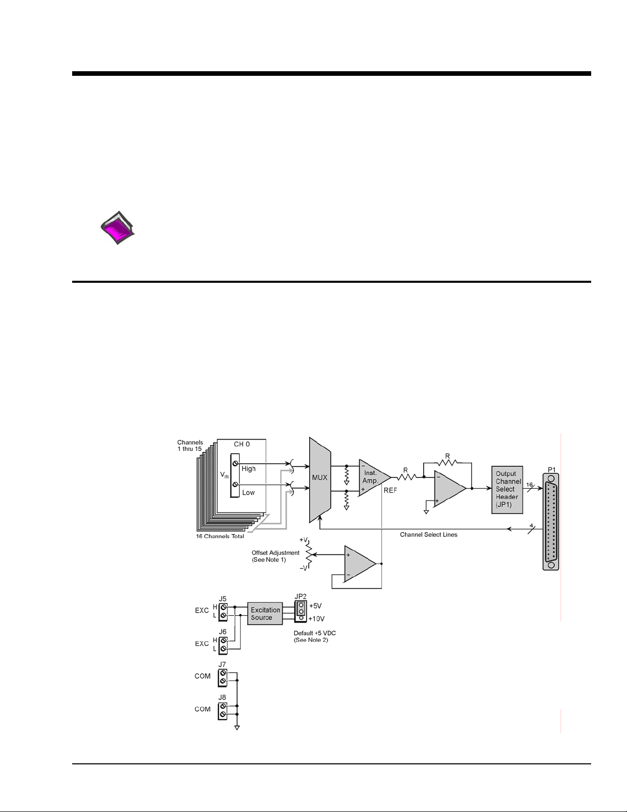
Note 1: Offset adjustment is only intended for use during
Note 2: JP2 is used to select an excitation source output
calibration.
voltage of +5 VDC or +10 VDC. The factory default
is +5 VDC.
DBK80 Block Diagram
DBK Option Cards and Modules 989494 DBK80 pg. 1
Page 2
Hardware Setup
Card Connection
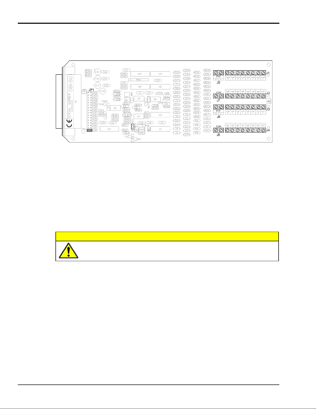
Referring to the figure above, voltage input signals are connected to the screw terminal blocks labeled J1,
J2, J3, and J4. Each channel is labeled with “H” and “L” to denote its polarity. These inputs accept
voltages up to ±10 VDC.
DBK80 Board Layout
Excitation Source
J5 and J6 provide the excitation source output, again labeled with “H” and “L” to denote polarity. Note
that J5 and J6 are connected in parallel. There is only one voltage source; two connectors are simply
provided for wiring convenience.
The excitation source is ground-referenced, not floating. That is, its low terminal is connected to the
ground of the Daq device. It is designed to interface to circuits where it is the only power source, or where
its connection is electrically isolated from other power sources. An example of the latter is an optocoupler.
CAUTION
Do not connect the excitation source to a non-isolated, powered circuit. Making such a
connection can cause damage to both the DBK80 and to the circuit under test.
The excitation source outputs should also be used together, with the “L” of the source providing the ground
reference to the connecting circuit. This provides two benefits. It maintains the accuracy of the source,
since the regulation of the “H” terminal is referenced to the “L” terminal. It also returns the load current
directly to its source, where its path is designed to not influence any other part of the measurement system.
DBK80 pg. 2 989494 DBK Option Cards and Modules
Page 3

Three examples of using the excitation source follow. They are Position Sensing, Resistance/Thermistor
Measurement, and Reading a Transducer.
Source Impedance and Settling Time
High speed multiplexing of signal sources with non-zero impedance will result in reading errors caused by
settling time. In the simplest form, a multiplexing system consists of a group of switches, with internal
resistance, and an output capacitance at the input of an amplifier feeding an A/D converter with a samplehold circuit on the input. During the short time a channel signal is connected to the A/D amplifier, the
signal must charge the output capacitance to the true value of the signal so that the sample-hold captures an
accurate value for the A/D converter to digitize. If the source has significant internal impedance the
voltage reading will be reduced.
DBK Option Cards and Modules 989494 DBK80 pg. 3
Page 4

Source impedance below 1000 ohms will create negligible error. Above 1000 ohms, the effects are
increasingly noticeable. An accurate source in series with a variable resistance will readily demonstrate
this. Although the effect is exponential, an easy reference point to remember is that 25K of source
impedance will result in approximately a 10% error.
Reading Error vs. Source Resistance
Analog Ground
J7 and J8 provide access to analog ground. The most common use for them is to provide a ground
reference point for differential measurements. This is discussed in the Signal Management section of
Chapter 1.
Card Configuration
Configuration of the DBK80 involves setting the channel address and selecting the
excitation output voltage.
Up to sixteen DBK80 cards can be attached to a single LogBook or Daq device, providing
up to 256 differential input channels.
Since multiple cards are connected via a parallel interface, each card must have a unique
channel address. To assign a channel number to the card, locate the 16×2-pin header
(labeled JP1). JP1’s jumper locations are labeled CH0 through CH15. Place the jumper
on the two pins that correspond with the intended channel.
Although J7 and J8 are electrically equivalent to the "L" signal of the excitation source,
they should never be used as the return point for the excitation source.
Only one channel configuration jumper is to be used per card.
Each card in the system must have a unique jumper setting.
DBK80 pg. 4 989494 DBK Option Cards and Modules
Page 5

The excitation output voltage is set via JP2.
JP2 Location Reference
The above figure is of a partial DBK80. JP2 is shown selected to +5VDC. Note that the card’s overlay for
JP2’s voltage selection, also depicted in the figure, indicates the jumper positions that are required to select
the +5 or +10 VDC excitation output.
DaqBook/100 Series & /200 Series and DaqBoard [ISA type] Configuration
Use of a DBK80 with a DaqBook/100 Series & /200 Series devices, or with an ISA-type DaqBoard,
requires the configuration of jumpers JP1 and JP4 located on the DaqBook/100 Series & /200 Series
devices, or DaqBoard [ISA type], as applicable.
1. If not using auxiliary power, set the JP1 jumper for Analog Option Card Use,
also referred to as the expanded analog mode.
Note:
These jumpers do not
apply to /2000 Series
Devices.
Required Jumper Settings in DaqBook/100 Series & /200 Series
and ISA-Type DaqBoards
The JP1 default position (above) is necessary to power the interface circuitry of the
DBK80 via the internal ±15 VDC power supply. If using auxiliary power (e.g.,
DBK32A or DBK33) you must remove both JP1 jumpers.
Refer to Power Requirements in the DBK Basics section and to the DBK32A and
DBK33 sections for more detailed information, as applicable.
2. For DaqBook/100, DaqBook /112, and DaqBook /120 only, place the JP4 jumper in the single-ended
mode.
Note: Analog expansion cards convert all input signals to single-ended voltages that are referenced to
analog common.
DBK Option Cards and Modules 989494 DBK80 pg. 5
Page 6

DaqBook/2000 Series and DaqBoard/2000 Series Configuration
No jumper configurations are required for the /2000 series devices.
Software Setup
The DBK80 has no special software settings. The software controls are equivalent to those for a direct
connection; e.g., for a DaqBoard/2000 Series board there are Type selections of x1 to x64, representing the
internal gain of that board. When using the DBK8 0 with that board you will have the same Type options,
since the DBK80 is always a constant gain of x1.
Note that there is no software control related to the excitation source. The selection of a +5 VDC or
+10 VDC source is determined by JP2.
Reference Notes:
o DaqView users - Refer to Chapter 3, DBK Setup in DaqView.
o LogView users - Refer to Chapter 4, DBK Setup in LogView.
DBK80 - Specifications
Connector: DBK37 male, mates with P1 pinout on a DaqBook, DaqBoard,
or LogBook. The board includes screw-terminals for signal connection.
Gain Ranges: 1, x1
Inputs: 16 differential voltage inputs
Maximum Voltage Range: ±10 V
Input Impedance: 20M Ohm
Accuracy: ±[0.025% +150 µV] (typ), ±[0.1% +250 µV] (max)
Noise: 60 µVrms (typ)
Maximum Input Voltage (without damage): ±25 V
3 dB Bandwidth: 2.6 MHz
CMRR: 80 dB typ
Excitation Voltage: 1 channel, jumper-selectable to +5 V or +10 V
Excitation Voltage Accuracy: ±0.5%
Excitation Voltage Current Limit: 20 mA Src, 1 mA Sink
Power: 25 mA max from ±15 V (with no load on excitation voltage)
DBK80 pg. 6 989494 DBK Option Cards and Modules
 Loading...