

Page 1
DBK70
Vehicle Network Interface
USER’S MANUAL
DBK70 Vehicle Network Interface
1056-0901 rev 6.1
Requires one of the following
Operating Systems:
Windows 2000
Windows XP
IOtech
25971 Cannon Road
Cleveland, OH 44146-1833
*372538B-01*
372538B-01
(440) 439-4091
Fax: (440) 439-4093
sales@iotech.com
productsupport@iotech.com
www.iotech.com
Page 2

Warranty Information
Your IOtech warranty is as stated on the product warranty card. You may contact IOtech by phone,
fax machine, or e-mail in regard to warranty-related issues.
Phone: (440) 439-4091, fax: (440) 439-4093, e-mail: sales@iotech.com
Limitation of Liability
IOtech, Inc. cannot be held liable for any damages resulting from the use or misuse of this product.
Copyright, Trademark, and Licensing Notice
All IOtech documentation, software, and hardware are copyright with all rights reserved. No part of this product may be
copied, reproduced or transmitted by any mechanical, photographic, electronic, or other method without IOtech’s prior
written consent. IOtech product names are trademarked; other product names, as applicable, are trademarks of their
respective holders. All supplied IOtech software (including miscellaneous support files, drivers, and sample programs)
may only be used on one installation. You may make archival backup copies.
CE Notice
Many IOtech products carry the CE marker indicating they comply with the safety and emissions standards of the
European Community. As applicable, we ship these products with a Declaration of Conformity stating which
specifications and operating conditions apply.
Warnings, Cautions, Notes, and Tips
Refer all service to qualified personnel. This caution symbol warns of possible personal injury or equipment damage
under noted conditions. Follow all safety standards of professional practice and the recommendations in this manual.
Using this equipment in ways other than described in this manual can present serious safety hazards or cause equipment
damage.
This warning symbol is used in this manual or on the equipment to warn of possible injury or death from electrical
shock under noted conditions.
This ESD caution symbol urges proper handling of equipment or components sensitive to damage from electrostatic
discharge. Proper handling guidelines include the use of grounded anti-static mats and wrist straps, ESD-protective
bags and cartons, and related procedures.
This symbol indicates the message is important, but is not of a Warning or Caution category. These notes can be of
great benefit to the user, and should be read.
In this manual, the book symbol always precedes the words “Reference Note.” This type of note identifies the location
of additional information that may prove helpful. References may be made to other chapters or other documentation.
Tips provide advice that may save time during a procedure, or help to clarify an issue. Tips may include additional
reference.
Specifications and Calibration
Specifications are subject to change without notice. Significant changes will be addressed in an addendum or revision to
the manual. As applicable, IOtech calibrates its hardware to published specifications. Periodic hardware calibration is
not covered under the warranty and must be performed by qualified personnel as specified in this manual. Improper
calibration procedures may void the warranty.
Quality Notice
IOtech has been an ISO 9001 registered firm since 1996. Prior to shipment, we thoroughly test our products and
review our documentation to assure the highest quality in all aspects. In a spirit of continuous improvement,
IOtech welcomes your suggestions.
ii
Page 3

Table of Contents
1 – Unpacking the DBK70
2 – Introduction
3 – System Setup
Software Installation …… 3-1
Powering the System Using Auxiliary Power or Vehicle Bus Power …… 3-1
Configuring a DBK70 …… 3-2
Using a DBK70 in Stand-Alone Mode …… 3-2
Using a DBK70 with a WaveBook …… 3-4
Using a DBK70 with a Daq Product or LogBook …… 3-6
4 – Hardware Reference
DBK70 Connectors …… 4-1
Power Issues …… 4-4
LED Operation …… 4-4
Vehicle Diagnostic Connectors …… 4-5
Serial Port Cable, CA-212 RS-232 [Included] …… 4-6
Vehicle Network Cable, CA-210 [Included] …… 4-6
J1939/J1708
Analog Output Cable, CA-208 [Optional] …… 4-8
Chassis Label …… 4-9
Card Installation …… 4-10
9-pin Deutsch Connector, Vehicle Network Cable, CA-218 [Optional] …… 4-7
5 – PidPRO and PidPRO+
Introduction …… 5-1
PIDs, Analog Output Channels, and Virtual Channels …… 5-3
Comparing PidPRO to PidPRO+ …… 5-4
Database Concepts …… 5-5
PidPRO Quick-Start …… 5-6
Database Management …… 5-9
Reference Guide …… 5-11
Main Window …… 5-11
Database Item View Window …… 5-17
Detailed View …… 5-18
Summary View …… 5-28
Network Monitor
Quick Start for Network Monitor …… 5-31
Reference for Network Monitor …… 5-32
[ PidPRO+ Only ] ……5-31
Parsing Serial Strings …… 5-34
Introduction …… 5-34
Examples …… 5-34
C++ …… 5-34
VB …… 5-34
DASYLab …… 5-34
LogView …… 5-35
DBK70 User’s Manual 919092 v
Page 4

6 – Fundamentals of Obtaining Vehicle Data
7 – Deciphering the PID $00, $20, and $40 Messages
8 – Troubleshooting
9 – Specifications
Appendix A – DBK70 Firmware Upgrade Instructions (p/n 1056-0902)
Appendix B – Scale and Offset in Summary View
vi 919092 DBK70 User’s Manual
Page 5
Unpacking the DBK70 1
Electrostatic Discharge (ESD)
The discharge of static electricity can damage some electronic components. Semiconductor devices are especially susceptible to ESD damage. You should always
handle components carefully, and you should never touch connector pins or circuit
components unless you are following ESD guidelines in an appropriate ESD
controlled area. Such guidelines include the use of properly grounded mats and wrist
straps, ESD bags and cartons, and related procedures.
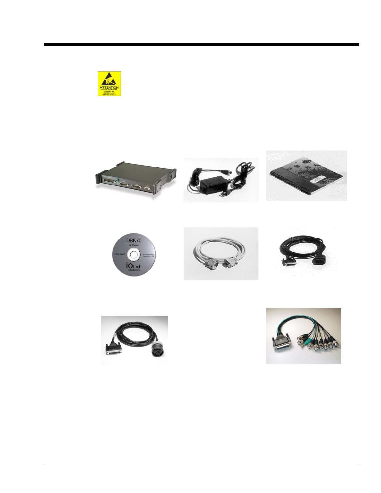
Package Contents
DBK70 is typically shipped with the following items, with exception of the “optional” cables.
DBK70
AC Power Adapter & Cable
(TR-40U and CA-1)
DBK70 User’s Manual*
(1056-0901)
Setup Software CD
(1056-0600)
Serial Port Cable
(CA-212)
Optional
Vehicle Network Cable
(CA-210)
J1939/J1708** Vehicle
Network Cable (CA-218)
9-Pin Deutsch Connector
OPTIONAL** OPTIONAL
Items shown are not to scale.
Analog Output Cable
(CA-208)
If any part of your order is missing or damaged, contact IOtech or your sales agent.
The e-mail address for sales is: sales@iotech.com.
The e-mail address for product support is: productsupport@iotech.com.
* Note: The hardcopy version of the user’s manual may be replaced by a PDF manual on the CD.
**Note: J1708 is no longer supported by DBK70 software.
DBK70 User’s Manual 919192 Unpacking the DBK70 1-1
Page 6

1-2 Unpacking the DBK70 919192 DBK70 User’s Manual
Page 7
Introduction 2
The DBK70 is an electronic module that can be quickly configured to generate analog output signals that
are proportional to many typical vehicle characteristics based on a single connection to the vehicle’s
diagnostic connector. The DBK70 provides sensor module signals of vehicle characteristics from data
acquired from a vehicle’s data bus (e.g., J1850, J1850 VPW, J1850 PWM, Class 2, SCP, CAN, etc.).
Once configured using the included software, the DBK70 will capture the selected vehicle network
message and convert the imbedded data into a proportional analog output suitable for measurement with
any IOtech data acquisition product or equivalent.
Monitoring the messages transmitted on the network eliminate the need to outfit the vehicle under test with
transducers and wiring that would be redundant with the vehicle’s existing transducers and wiring. Where
the data rate available from a vehicle’s data bus is satisfactory, the DBK70 can create output waveforms
comparable to direct transducer measurement.
Depending on availability through the data bus, the DBK70 is also able to generate signals proportional to
data internal to a vehicle’s electronic modules, which is typically inaccessible for monitoring or recording.
Through the vehicle data bus, the DBK70 can obtain such data from any vehicle module accessible through
the same vehicle data bus that is used for vehicle diagnostics.
Through the DBK70, vehicle data contained in normally occurring messages used for the operation of the
vehicle and/or available through diagnostic protocols can be monitored and used to generate scaled, analog
output. Every DBK70 analog output channel is independently configured. Each data received and
processed has two independent sets of scaling parameters, one to control the output signal and the other to
format the data for real time display on a PC.
DBK70 User’s Manual 946898 Introduction 2-1
Page 8
Since the DBK70 contains a non-volatile memory that holds all of its setup parameters, the PC need only
be connected to initially configure the DBK70 or to make configuration changes. During normal operation,
no PC connection is required. In addition to configuring the DBK70, the included software also allows the
operator to view parameters on-screen in real-time. The DBK70 configuration and monitoring software
runs on any PC that is using Windows 95, 98, Me, 2000, or NT.
The DBK70’s operation is completely configurable through the use of supplied software and a
configuration database. Through this software and database a user can quickly change the configuration of
any and all output channels, monitor in real time the operation of each output channel, and/or create or edit
members of the configuration database.
The DBK70 can be operated as an accessory to IOtech’s DaqBook, DaqBoard, LogBook, or WaveBook
product lines, or as a stand-alone device providing analog outputs for any voltage measurement instrument
including hand-held meters and strip chart recorders.
CA-208
Used with IOtech Data Acquisition
Stand-alone Mode
2-2 Introduction 946898 DBK70 User’s Manual
Page 9

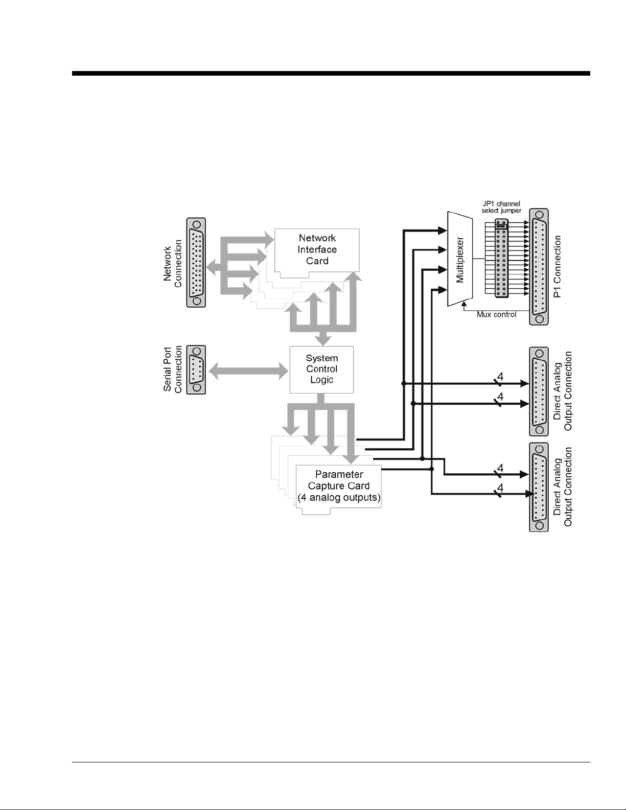
Typically, operation of the DBK70 requires the steps indicated in the following block diagram. Note that
the term PID means Parameter Identifier. For CAN [including J1939] the terms PGN (Parameter Group
Number) and SPN (Suspect Parameter Number) are used.
DBK70 User’s Manual 946898 Introduction 2-3
Page 10

2-4 Introduction 946898 DBK70 User’s Manual
Page 11

System Setup 3
Software Installation …… 3-1
Powering the System Using Auxiliary Power or Vehicle Bus Power …… 3-1
Configuring a DBK70 …… 3-2
Using a DBK70 in Stand-Alone Mode …… 3-2
Using a DBK70 with a WaveBook …… 3-4
Using a DBK70 with a Daq Product or LogBook …… 3-6
Software Installation
DBK70 Software and Database Requirements
The DBK70 software and database runs under Windows 98, Me, 2000 or XP.
DBK70 Software and Database Installation
A CD ROM is distributed with the DBK70. This CD ROM contains a copy of the DBK70 software and a
copy of a starter DBK70 Database (i.e., DBK70.mdb).
To install the DBK70 software and the DBK70 Database, use the following procedure.
Run Setup.exe
Place the DBK70 CD ROM in your CD ROM drive. If the Windows Auto Detect option is set, the SETUP
program will start automatically. If not, select “Run” from the Windows “Start” menu. Browse, if
necessary, and run the “Setup.exe” program.
Carefully follow the screen prompts to install your software.
Powering the System Using Auxiliary Power or Vehicle Bus Power
The DBK70 receives its access to the vehicle’s data bus and power through a connection to the vehicle’s
diagnostic connector. The CA-210 cable is used to connect the DBK70 to the vehicle’s standard
Diagnostic Connector (i.e., SAE J1962). The other end of this cable is connected to the DBK70. Typically,
the power pins on the vehicle’s diagnostic connector are only active when the vehicle is on.
The Vehicle Diagnostic cable must be connected to the DBK70 first and the vehicle’s
diagnostic connector second.
The Auxiliary Power input is primarily used to operate the DBK70 when not connected to a vehicle. In
some instances, it may be preferable to configure the DBK70 outside of the vehicle, in an office or lab
setting. Use the included AC power adapter in these circumstances. When not connected to a vehicle
network, real-time message values cannot be monitored in the software.
DBK70 User’s Manual 927994 System Setup 3-1
Page 12
Configuring a DBK70
The DBK70 generates analog output signals that are proportional to vehicle data the DBK70 acquires from
a vehicle’s data bus.
The DBK70 uses a connection to the vehicle’s diagnostic connector to obtain access to the vehicle’s data
bus and to obtain the power it needs to operate and to create the output signals. A serial connection to a PC
is used when configuring the DBK70’s output channels and/or to monitor the vehicle data being processed
by the DBK70.
Once its output channels are configured, the
operation of the DBK70 is automatic.
Whenever the DBK70 is connected to vehicle
power, it loads the configuration information
last saved in its non-volatile memory, and
begins processing data and generating output
signals. As the DBK70 receives data from the
data bus, it creates scaled analog output signals
based on the received data. Whenever the
data associated with an output channel is
unavailable, a channel specific default
output signal value is generated.
To configure the DBK70, connect it to your PC’s serial port and launch the included software application.
The software provides database management and channel configuration services.
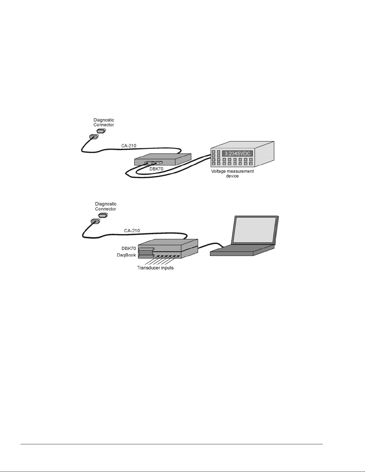
Using a DBK70 in Stand-Alone Mode
Use the PC’s serial port to configure the DBK70
The DBK70 can be used with any voltage measurement instrument in a stand-alone mode. After
configuring the DBK70 with the included software, connect it to the vehicle’s diagnostic connector. When
the DBK70 receives power from the vehicle, it will immediately begin monitoring the network and
updating its analog outputs to reflect the values of the desired messages, as per its saved configuration.
Attach your voltage measurement device to the DBK70’s analog outputs through the analog output
connectors.
Reference Note:
Refer to page 4-3 for more information.
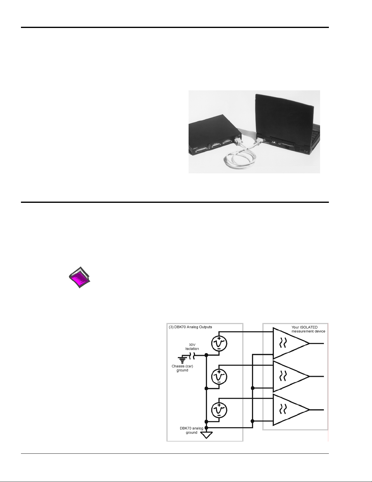
The DBK70 provides single-ended analog outputs, where all outputs are referenced to the same internal
analog ground. Follow the recommended guidelines below to get the best quality readings from your
measurement equipment.
Isolated Measurements
When used with a measurement
device having isolated inputs, connect
any of the DBK70’s ground pins to
each of the low-side inputs of the
measurement device. Attach each of
the DBK70 analog outputs to the highside inputs of the measurement device.
It is not necessary to tie the ground of
the DBK70 to the ground of the
measurement device.
3-2 System Setup 927994 DBK70 User’s Manual
Page 13
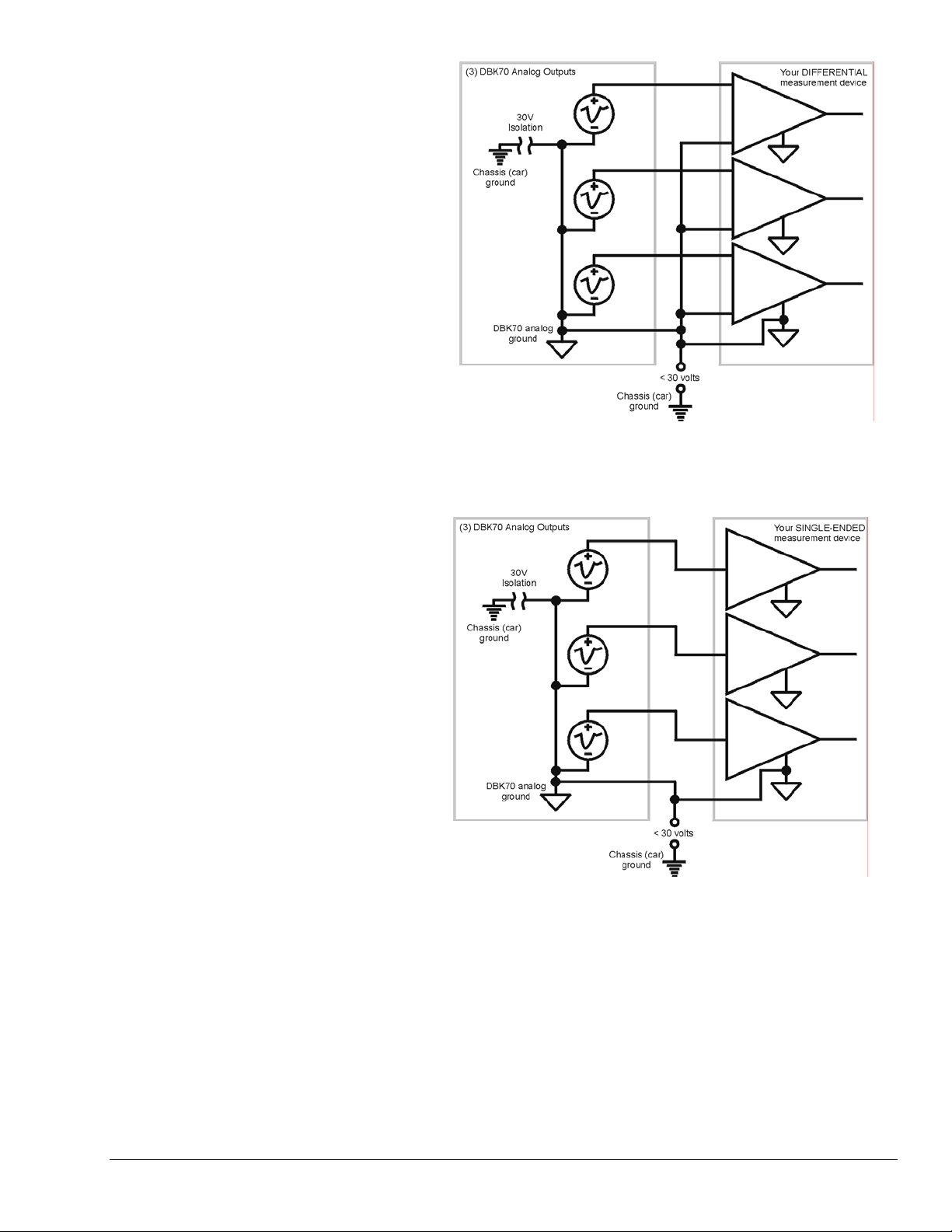
Differential Measurements
When a differential input
measurement device is used, the
analog ground of the measurement
device must be connected to the
analog ground of the DBK70. This
ground cannot be greater than 30
volts above the vehicle’s chassis
ground.
Single-Ended Measurements
When measuring the DBK70
outputs with a single-ended
device, the analog grounds from
the DBK70 and the measurement
device must be tied together.
DBK70 User’s Manual 927994 System Setup 3-3
Page 14
Using a DBK70 with a WaveBook
The DBK70 has both straight-through and multiplexed outputs. The multiplexed outputs are designed
specifically for use with IOtech’s Daq* and LogBook products. The straight-through outputs can be used
with any measurement device, including IOtech’s WaveBook products.
Reference Note:
Refer to the block diagram on page 2-1 to better understand the relationship between the
multiplexed and straight through outputs.
3-4 System Setup 927994 DBK70 User’s Manual
Page 15
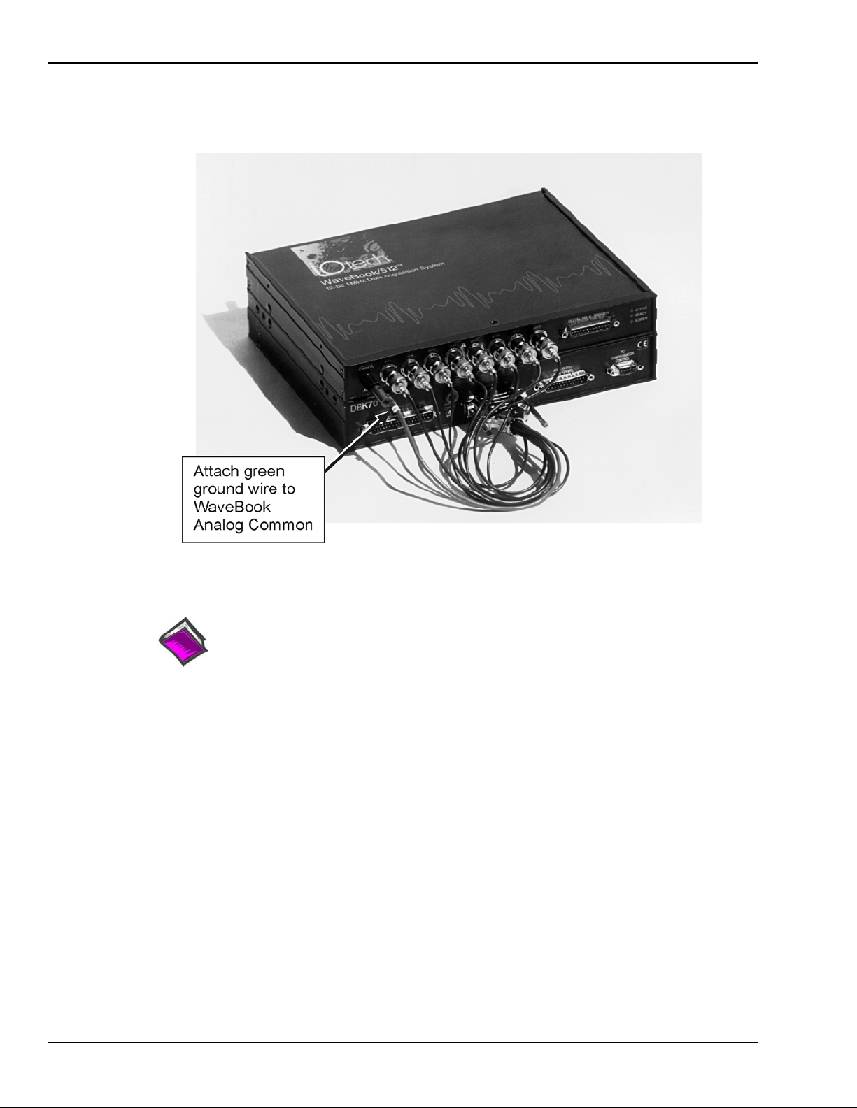
To use the DBK70 with a WaveBook, connect the DBK70’s analog outputs to unused WaveBook voltage
inputs using the optional CA-208 cable. A single CA-208 supports 8 channels; thus two CA-208 cables are
required to connect all 16 DBK70 analog outputs to a WaveBook and/or to any WaveBook expansion
modules.
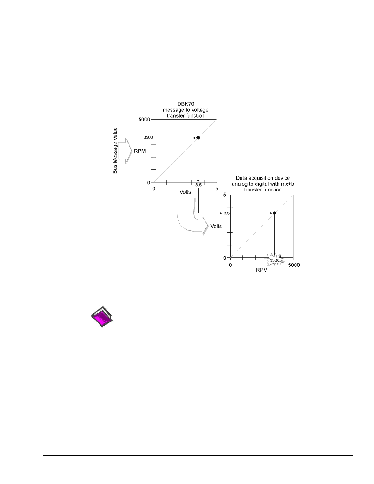
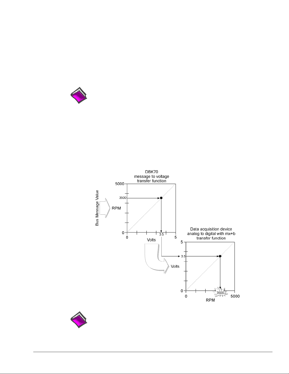
In WaveView, the data acquisition software included with the WaveBook, use the mx+b (scale and offset)
feature to convert the DBK70 voltage values into engineering units. For example, if the DBK70 is
capturing vehicle RPM in the range of 0 to 5000 RPM and scaling the result to 0 to 5 volts, setting the “m”
in WaveView to 1000 will convert the incoming voltage to RPM. This technique can be used in any data
collection software package to convert the DBK70’s output voltage to engineering units.
Reference Note:
mx + b values are included in a Microsoft Excel file: mx+b values.xls. The file is
located in the root directory of your DBK Configuration CD (p/n 1056-0600).
DBK70 User’s Manual 927994 System Setup 3-5
Page 16
Using a DBK70 with a Daq* Product or LogBook
The DBK70 has both straight-through and multiplexed outputs. The multiplexed outputs are designed
specifically for use with IOtech’s Daq* and LogBook products. The straight-through outputs can be used
with any measurement device, including IOtech’s WaveBook products.
Reference Note:
Refer to the block diagram on page 2-1 to better understand the relationship between the
multiplexed and straight through outputs.
To use the DBK70 with a DaqBook, DaqBoard, Daq PC-Card, or LogBook, connect the DBK70’s P1
connector to the P1 connector of any of the aforementioned data acquisition products via a ribbon cable
(CA-37).
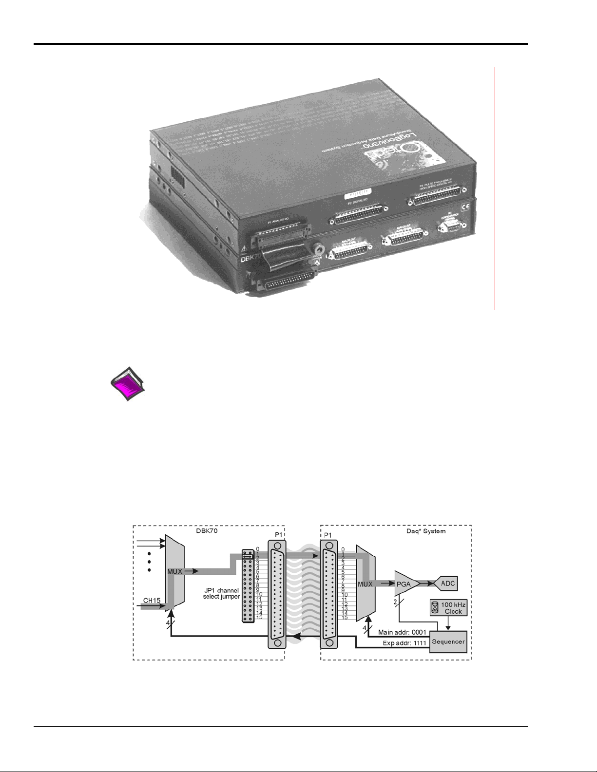
From the perspective of, for example, the DaqBook, the DBK70 represents an analog input expansion
module that is multiplexing 16 analog inputs into one of the DaqBook’s analog input channels. The
example diagram below shows the JP1 jumper in the DBK70 set to channel 1. When the sequencer selects
base channel 1 and expansion channel 15, the voltage signal passes through the highlighted path.
3-6 System Setup 927994 DBK70 User’s Manual
Page 17
• The Daq* sequencer selects the channel and gain by controlling multiplexers (MUX) and
programmable gain amplifiers (PGA) in both the Daq* and the DBK. The sequencer uses 4 expansion
address lines to provide 16 unique channel addresses for each base channel.
• The DBK70 multiplexer selects 1 of 16 (max) channels as directed by the sequencer. The selected
signal goes to the channel-selection jumper, and then to the Daq* via P1.
• The Daq* multiplexer selects 1 of 16 base channels from P1 input lines as directed by the sequencer.
The selected signal goes to the PGA and then to the A/D converter (A/D).
• The P1 interface has a signal line for each of the 16 base channels.
• The JP1 channel select jumper in the DBK70 can be placed on pins for channel 0 through channel 15.
Each DBK70 in the system must occupy a different base unit channel. The factory default setting for the
JP1 jumper is channel 0.
Reference Note:
Refer to the DaqView or LogView documentation for instructions on how to inform the
software of the presence of DBK modules and cards.
Using the steps described in the DaqView or LogView documentation, the user must provide the location
of the JP1 jumper to the software.
In DaqView or LogView, use the mx+b (scale and offset) feature to convert the DBK70 voltage values into
engineering units. For example, if the DBK70 is capturing vehicle RPM in the range of 0 to 5000 RPM and
scaling the result to 0 to 5 volts, setting the “m” in WaveView to 1000 will convert the incoming voltage to
RPM. This technique can be used in any data collection software package to convert the DBK70’s output
voltage to engineering units.
Reference Note:
mx + b values are included in a Microsoft Excel file: mx+b values.xls. The file is
located in the root directory of your DBK Configuration CD (p/n 1056-0600).
DBK70 User’s Manual 927994 System Setup 3-7
Page 18

3-8 System Setup 927994 DBK70 User’s Manual
Page 19
Hardware Reference 4
DBK70 Connectors …… 4-1
Serial Configuration Port …… 4-1
Network Port …… 4-2
Direct Parameter Analog Output Ports 1 and 2 …… 4-3
P1 Multiplexed Output Port …… 4-3
Auxiliary Power Connectors …… 4-4
Power Issues …… 4-4
LED Operation …… 4-4
Vehicle Diagnostic Connectors …… 4-5
Serial Port Cable, CA-212 RS-232 [Included] …… 4-6
Vehicle Network Cable, CA-210 [Included] …… 4-6
J1939/J1708
Analog Output Cable, CA-208 [Optional] …… 4-8
Chassis Label …… 4-9
Card Installation …… 4-10
Network Interface Cards …… 4-10
Analog Output Cards …… 4-11
DBK70 Connectors
9-pin Deutsch Connector, Vehicle Network Cable, CA-218 [Optional]…… 4-7 **
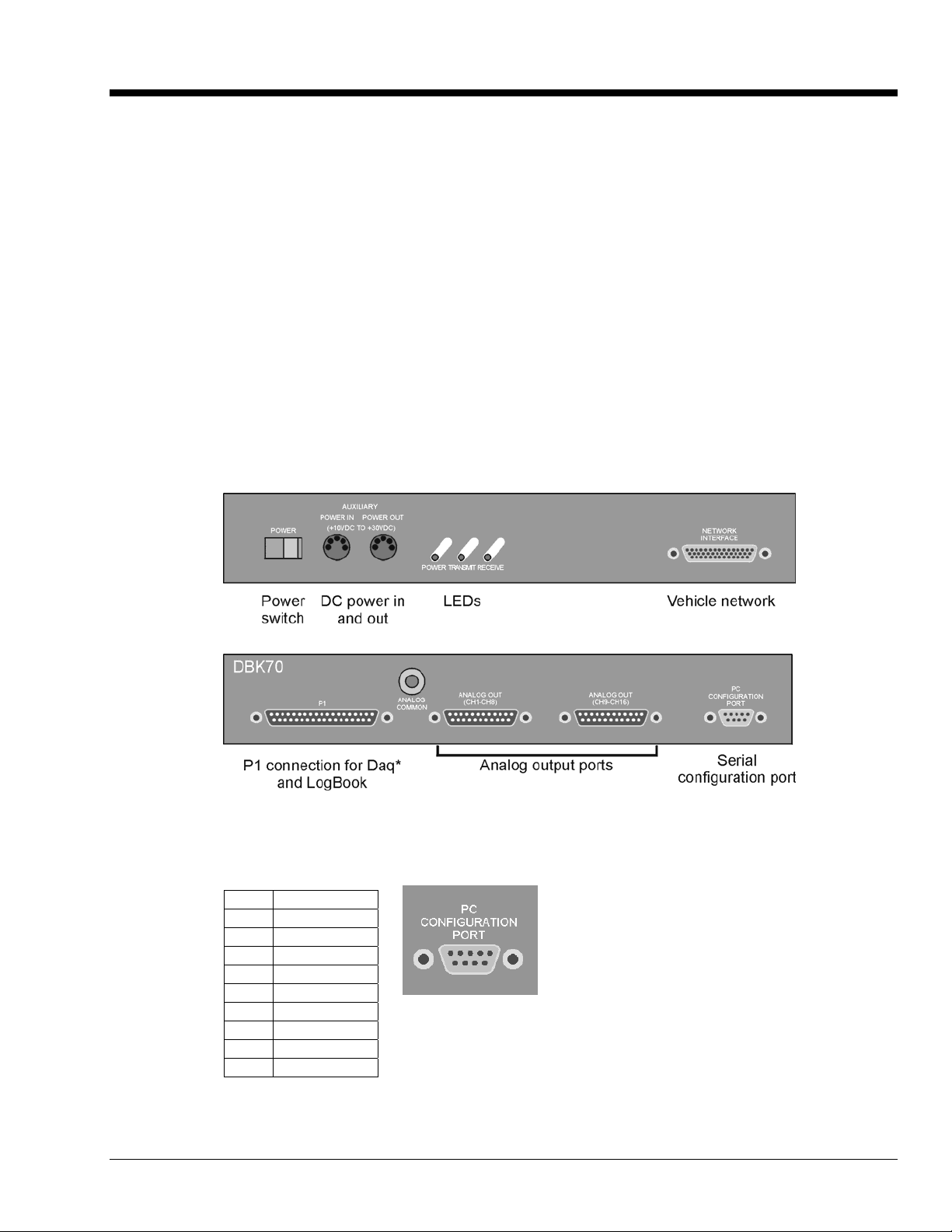
Serial Configuration Port
The Serial Configuration Port is used to configure the DBK70 using a PC and the included PC software.
Connect this port to the PC’s COM port using the included CA-212 cable.
Pin# Name
1 NC
2 Tx
3 Rx
4 NC
5 Analog Gnd
6 NC
7 CTS
8 RTS
9 NC
**
Note: J1708 is no longer supported by DBK70 software.
DBK70 User’s Manual 919092 Hardware Reference 4-1
Page 20

Network Port
The Network Port is used to attach the DBK70 to the vehicle’s network via the included CA-210 cable.
Pin# Pin#
1 Reserved 23 Reserved
2 Reserved 24 Reserved
3 Reserved 25 ISO9141-K
4 J1850(+) 26 Reserved
5 Reserved 27 J1708(-) **
6 Reserved 28 Reserved
7 Reserved 29 CAN+
8 Reserved 30 Reserved
9 Reserved 31 Reserved
10 Reserved 32 Reserved
11 J1708(+) ** 33 Reserved
12 Reserved 34 Reserved
13 CAN- 35 Reserved
14 Reserved 36 Ground
15 Reserved 37 Ground
16 Reserved 38 Reserved
17 J1850(+) 39 Reserved
18 Reserved 40 Reserved
19 Reserved 41 Reserved
20 J1850(-) 42 Battery VDC
21 Reserved 43 Battery VDC
22 Reserved
44 Reserved
**Note: J1708 is no longer supported by DBK70 software.
4-2 Hardware Reference 919092 DBK70 User’s Manual
Page 21
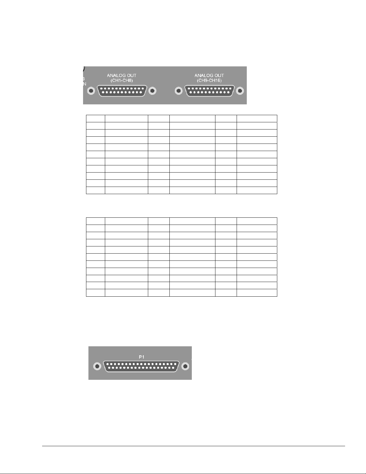
Direct Parameter Analog Output Ports 1 and 2
The Direct Parameter Analog Output Ports provide a direct connection to the analog outputs sourced by the
internal 4-parameter capture cards. If four cards are installed, 16 analog outputs will be available; channels
0-7 on Port 1 and 8-15 on Port 2. These can be directly connected to any high impedance input voltage
measurement device.
Port 1
Pin# Name Pin# Name Pin# Name
1 Analog out 1 11 NC 21 Analog Gnd
2 Analog out 2 12 NC 22 Analog Gnd
3 Analog out 3 13 NC 23 Analog Gnd
4 Analog out 4 14 Analog Gnd 24 Analog Gnd
5 Analog out 5 15 Analog Gnd 25 Analog Gnd
6 Analog out 6 16 Analog Gnd
7 Analog out 7 17 Analog Gnd
8 Analog out 8 18 Analog Gnd
9 NC 19 Analog Gnd
10 NC 20 Analog Gnd
Port 2
Pin# Name Pin# Name Pin# Name
1 Analog out 9 11 NC 21 Analog Gnd
2 Analog out 10 12 NC 22 Analog Gnd
3 Analog out 11 13 NC 23 Analog Gnd
4 Analog out 12 14 Analog Gnd 24 Analog Gnd
5 Analog out 13 15 Analog Gnd 25 Analog Gnd
6 Analog out 14 16 Analog Gnd
7 Analog out 15 17 Analog Gnd
8 Analog out 16 18 Analog Gnd
9 NC 19 Analog Gnd
10 NC 20 Analog Gnd
P1 Multiplexed Output Port
This port is for attaching the DBK70 to a DaqBook, DaqBoard, Daq PC-Card, or LogBook via a short
ribbon cable.
DBK70 User’s Manual 919092 Hardware Reference 4-3
Page 22

Auxiliary Power Connectors
Either port can be used to supply auxiliary power
to the DBK70. When attached to a vehicle
network, the vehicle will supply adequate power
for the DBK70, so no additional power need be
connected via the Auxiliary Power Connector. To
power the DBK70 in the lab or office, disengaged
from the vehicle network, use the included
external AC supply. The 2
connector is used to cascade externally supplied
power to another piece of data acquisition equipment.
Power Issues
There are 2 methods for powering a DBK70; applying DC power to either of its Auxiliary Power inputs or
through the vehicle network. When connected to a running vehicle, the vehicle power received from the
diagnostic connector is all that is necessary to power the DBK70 – no further power connections are
necessary.
In rare instances where power is not available on the diagnostic connector, the DBK70 can be powered
from its Auxiliary Power connector using a cigarette lighter power cord (IOtech p/n CA-198)
The Auxiliary Power input is primarily used to operate the DBK70 when not connected to a vehicle. In
some instances, it may be preferable to configure the DBK70 outside of the vehicle, in an office or lab
setting. Use the included AC power adapter in these circumstances.
nd
Auxiliary power
The 2 Auxiliary Power connectors are attached in parallel inside the DBK70. When power is supplied to
the DBK70 externally, the 2
equipment, like a DaqBook, WaveBook, or LogBook data acquisition product.
nd
connector can be used to cascade the power source to another piece of
LED Operation
Three LEDs on the front panel of the DBK70 provide feedback as to
the current state of the unit. When sufficient power supply voltage is
supplied, the Power LED will blink. When both power is applied and
network activity is sensed, the Power LED will remain solid. If the
DBK70 is powered but not connected to the vehicle network, no
activity will be sensed, therefore the Power LED will blink.
• When connected to the network of a running vehicle and the analog outputs are configured, if the
Power LED is not solidly illuminating, it is likely that the vehicle bus is malfunctioning or the
DBK70 network interface is not operating correctly. This could be due to having the incorrect
network interface installed in the DBK70.
• The Transmit LED will flash when the DBK70 is issuing a request message onto the network. If the
Update Rate field is set to 0 and/or the Message field is blank for all desired messages, the DBK70
will never issue messages onto the network, therefore the LED will never blink.
• The Receive LED will flash whenever any desired messages have been detected. A desired message
is defined as a message that the DBK70 has been configured to capture. If the Receive LED never
flashes, the desired bus messages, defined in the fields of the database, are not being detected. This
could be due to an incorrect message definition in the database, or that the desired message needs to
be requested before it is transmitted.
4-4 Hardware Reference 919092 DBK70 User’s Manual
Page 23
Vehicle Diagnostic Connectors
The J1962 Vehicle Diagnostic Connector is required on all new automobiles sold in the USA after model
year 1995. It may also be available on a few model year ‘94 and ‘95 vehicles sold in the USA. Tentatively,
it will also be required on all new automobiles sold in the EC in calendar year 2000 and later.
Different vehicle manufacturers may give different names to the vehicle’s diagnostic connector. Some may
call it the ALDL connector, the Class 2 connector, the SCP connector, the 16-Way, the J1850 connector, or
the diagnostic connector.
The vehicle’s diagnostic connector is typically mounted under the instrument panel on the driver’s side of
the vehicle. The connector is typically mounted in or near a center console or under the instrument panel on
the driver’s side of the vehicle.
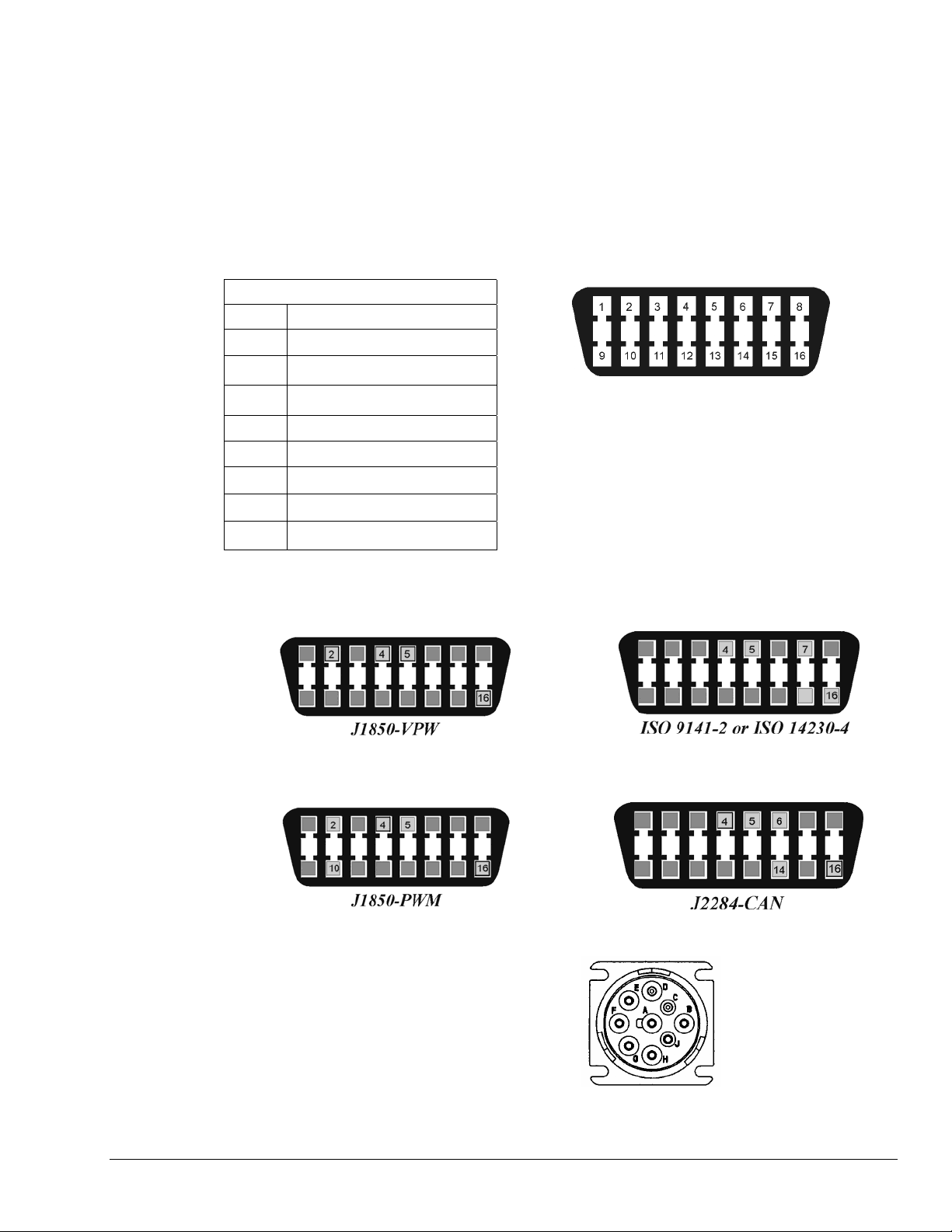
16-Way Diagnostic Connector Pinout
Pin# Description
2 J1850 Bus (+)
4 Chassis Ground
5 Signal Ground
6 CAN High
7 ISO 9141-2 K Line
10 J1850 Bus (-)
14 CAN Low
16 Battery Power
On year 1996 and later vehicles sold in the U.S., you can tell, with some level of certainty, which protocol
the vehicle uses. This is done by examining the metallic contacts in the OBD II connector, as indicated in
the following figures. Note that heavy-duty vehicles, such as busses, tractors, and trucks typically make
use of the J1939 diagnostic connector. J1939 is discussed on page 4-7.
The 16-pin diagnostic connector is known by many different
names. These include, but are not limited to: the 16-Way,
J1962, J1850, the Class 2, and the ALDL connector.
*Note: The 9-pin J1939 diagnostic connector, used in heavy-
J1850-VPW--The connector should have metallic
contacts in pins 2, 4, 5, and 16, but not 10.
16-Way Diagnostic Connector*
duty vehicles, is discussed on page 4-7.
ISO 9141-2 or ISO 14230-4--The connector
should have metallic contacts in pins 4, 5, 7,
and 16.
J1850-PWM--The connector should have metallic
contacts in pins 2, 4, 5, 10, and 16.
J1939 – The J1939 diagnostic connector should have
metallic contact pins in A, B, C, D, E, F, and G. This
connector is discussed in the section, J1939 Vehicle
Bus Cable, CA-218, on page 4-7.
DBK70 User’s Manual 919092 Hardware Reference 4-5
J2411-CAN-The connector should have metallic
contacts in pins 2, 4, 5, 6, 10, 14, and 16.
J1939
Page 24
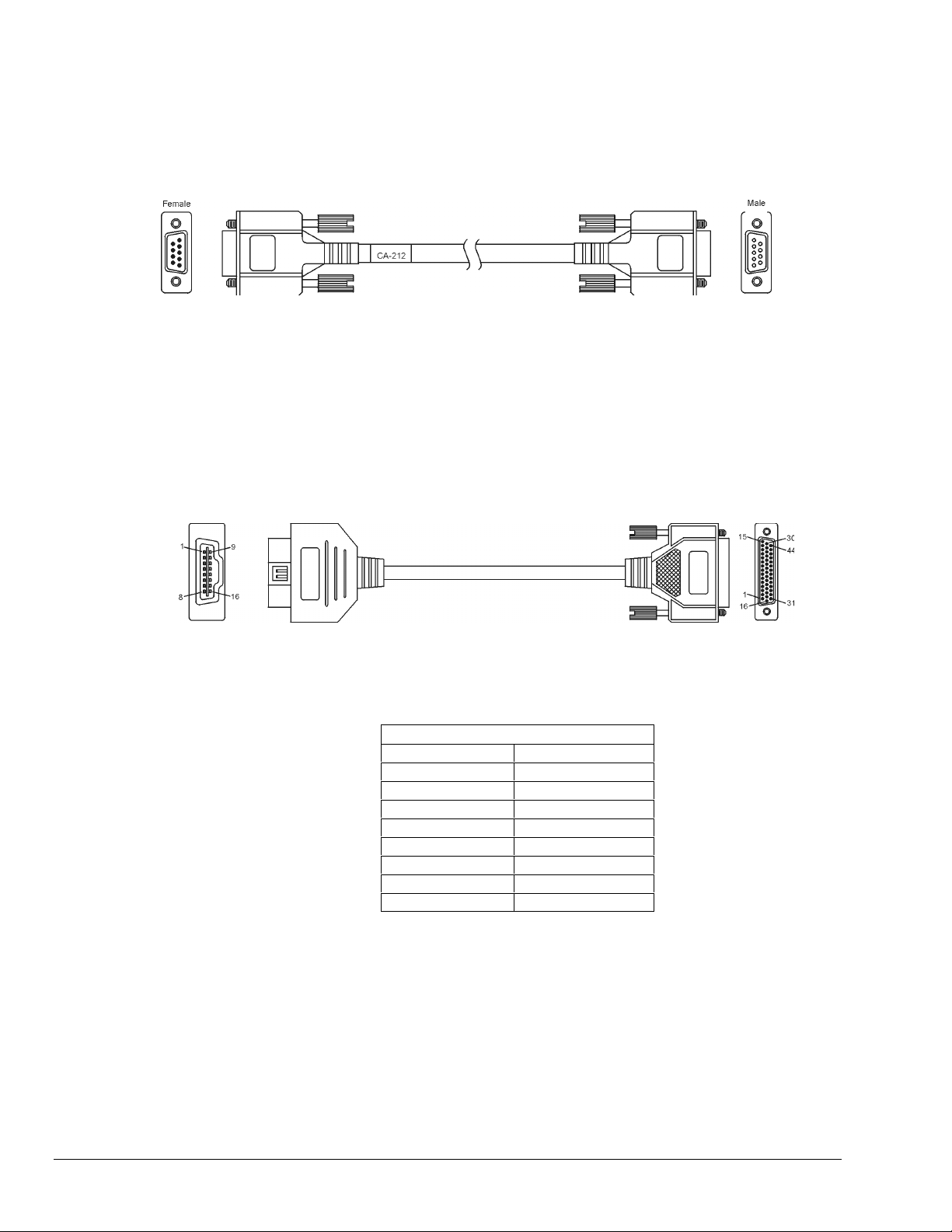
Serial Port Cable, CA-212 RS-232 [Included]
For the purpose of configuring the analog outputs, the DBK70 is connected to the PC via the included
CA-212 RS-232 cable. The CA-212 is a “straight through” serial cable – pins 1 through 9 on one end are
connected to pins 1 through 9 on the other end, respectively.
Vehicle Network Cable, CA-210 [Included]
The CA-210, included with the DBK70 provides a connection between the vehicle’s diagnostic connector
(OBD) and the DBK70, regardless of the type of interface supported by your vehicle. The connector is
typically located under the dashboard near the steering column.
CA-210 Pinout
OBD Connector DB44 Connector
2 4, 17
5 36, 37
6 29
7 25
10 20
14 13
16 42, 43
N/C 11, 27
4-6 Hardware Reference 919092 DBK70 User’s Manual
Page 25
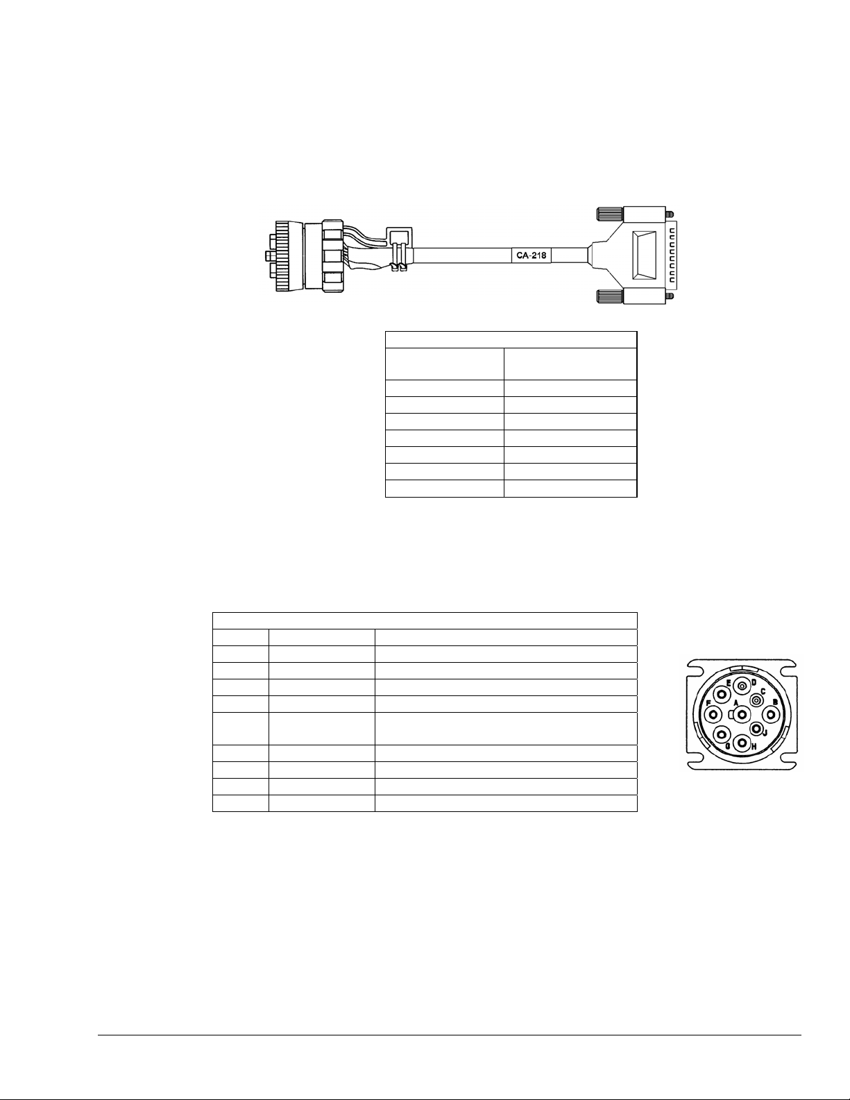
J1939/J1708** 9-pin Deutsch Connector,
Vehicle Network Cable, CA-218
CA-218 is a cable option. It enables a properly equipped DBK70 to communicate with vehicles that
support the J1939 or J1708** network protocol. These vehicles are typically of the heavy-duty variety and
include trucks and busses.
CA-218 Cable Pinout
J1939 Plug
Connector
A 36, 37
B 42, 43
C 29
D 13
E 36
F 27 **
G 11 **
[Optional]
DB44 Connector
J1939 Diagnostic Connector – The J1939 is a 9-pin, diagnostic connector.
J1939 should have metallic contact pins in A, B, C, D, and E.
SAE-J1939 Diagnostic Connector Pinout
Pin# Description Comment
A Battery (–)
B Battery (+)
C CAN_H
D CAN_L
E CAN_SHLD for SAE J 1939/11; or
no connection for ISO 11783-2
F SAE J 1708 (+) **
G SAE J 1708 (–) **
H -- Proprietary OEM use
J -- Proprietary OEM use
** J1708 is no longer supported by DBK70 software.
J1939/J1708**
Diagnostic
Connector
DBK70 User’s Manual 919092 Hardware Reference 4-7
Page 26

Analog Output Cable, CA-208 [Optional]
The optional CA-208 is used to break out the DB25 analog outputs to 8 BNCs.
CA-208 Pinout
BNC DB25 Pin
1 1
1 collar 14
2 2
2 collar 15
3 3
3 collar 16
4 4
4 collar 17
5 5
5 collar 18
6 6
6 collar 19
7 7
7 collar 20
8 8
8 collar 21
Green 25
4-8 Hardware Reference 919092 DBK70 User’s Manual
Page 27
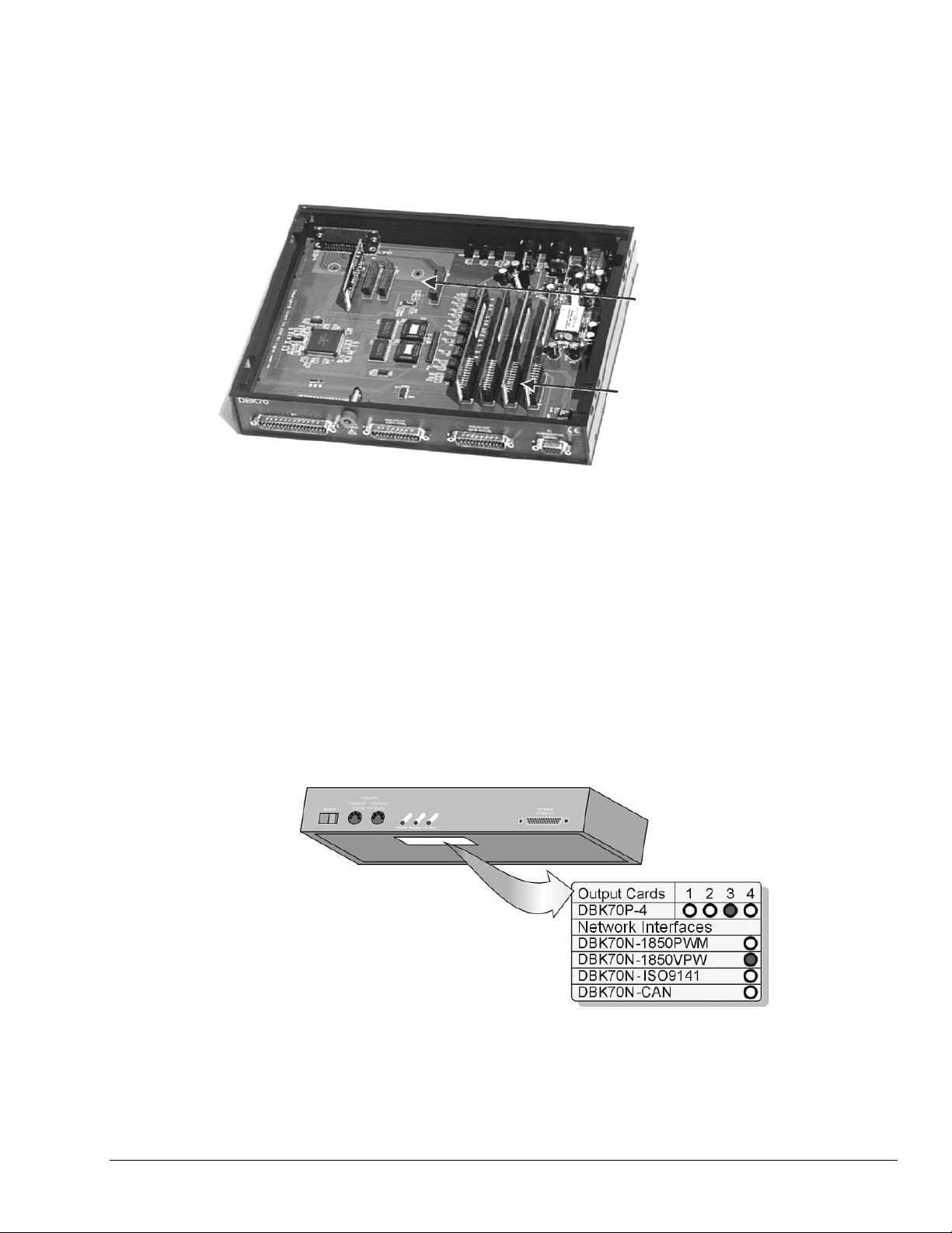
Chassis Label
The DBK70 has eight internal slots into which configuration cards can be installed. Four slots are reserved
for Network Interface cards, and four slots are for Parameter Capture cards. If only one network is to be
used (such as J1850-VPW), then only one Network Interface card is required. If multiple networks are to be
attached to one DBK70, then up to four Network Interface cards can be installed.
Network interface
module slots
Parameter capture
module slots
Each Parameter Capture card supplies 4 analog outputs, enabling the simultaneous capture of up to four
parameters, such as four different temperatures within the vehicle. To capture more than four parameters
simultaneously, additional Parameter Capture cards can be installed. Up to four cards, for a total of 16
network parameters, can be simultaneously captured by one DBK70.
Each DBK70 is configured with plug-in cards. A label located on the bottom of the DBK70 identifies the
cards installed at the factory. A colored in circle denotes the presence of the associated analog output card
or network interface card. Each analog output card (parameter capture card, DBK70-P4) has
four analog outputs. For example, if 3 cards are installed 12 parameters can be captured.
DBK70 User’s Manual 919092 Hardware Reference 4-9
Page 28
Card Installation
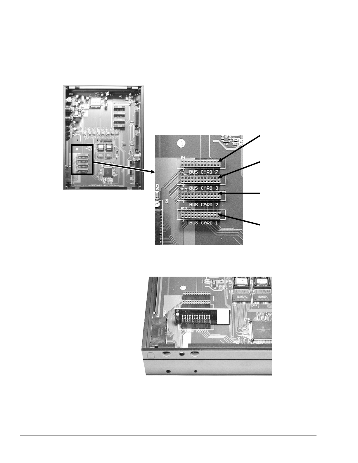
Network Interface Cards
The vehicle network card(s) are inserted into the 4 header sockets located adjacent to the network
connector of the DBK70, on the LED-side of the product. Network cards must be inserted into the proper
socket, as shown in the call-outs on the diagram below.
DBK70-CAN
IN Bus Card 7
DBK70-ISO-9141
or DBK70-J1708**
IN Bus Card 3
DBK7-J1850-PWM
IN Bus Card 2
DBK7-J1850-VPW
IN Bus Card 1
** DBK70-J1708 is no longer available for purchase. Reference is for existing owners.
4-10 Hardware Reference 919092 DBK70 User’s Manual
Page 29
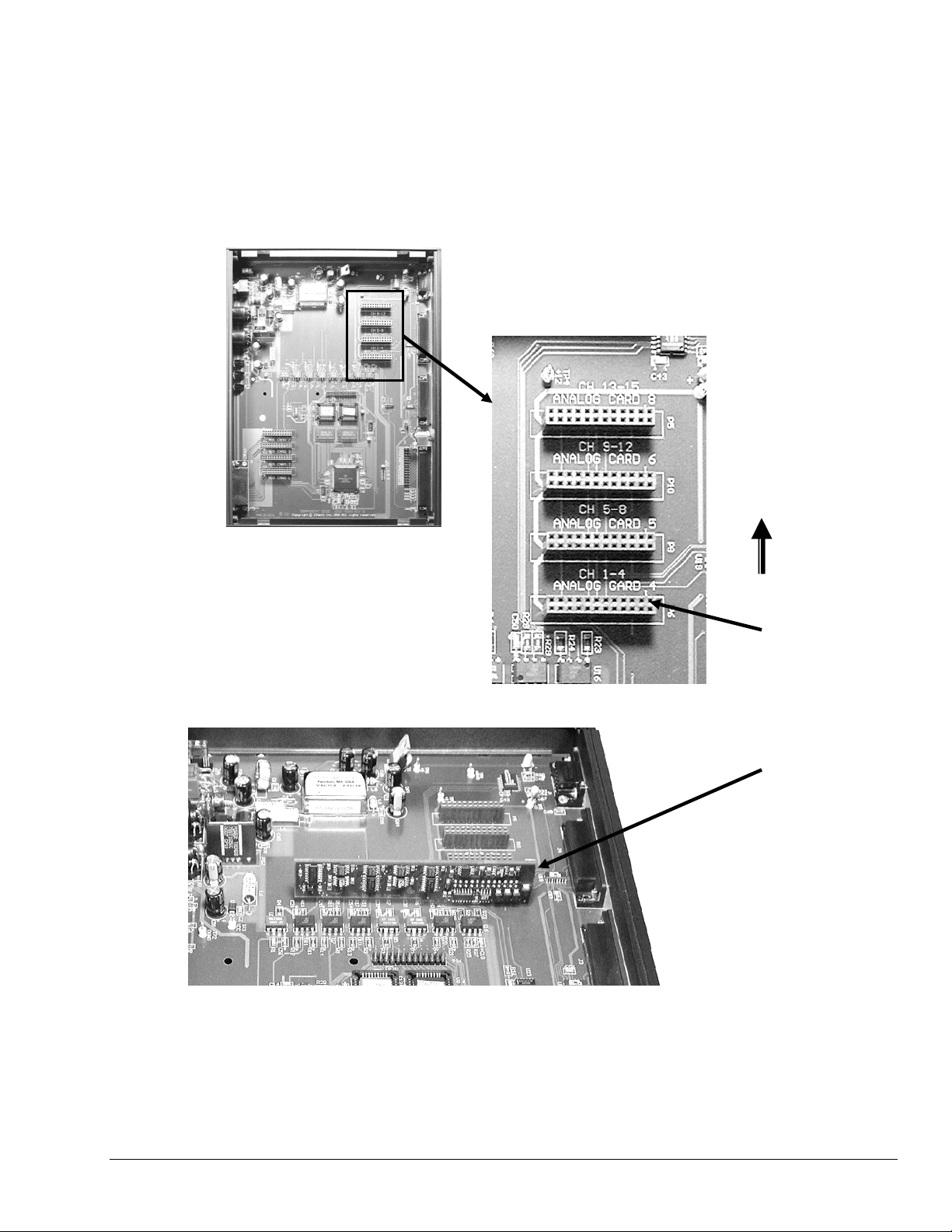
Analog Output Cards
The Analog Output Cards (DBK70-P4) are inserted into the 4 sockets adjacent to the analog output
connectors on the DBK70. Populate the sockets starting with the right-most socket continuing left until the
desired number of cards have been installed. Make sure no card has any open sockets to its right. The cards
must be oriented as shown in the diagram below.
When the DBK70 powers-up, the DBK70-P4s are immediately recognized and initialized. Each DBK70-P4
carries its own calibration constants on an on-board memory device so cards can be inserted in the field
without the necessity of re-calibration.
Add more cards
in this direction
st
The 1
card
goes here
Insert as
shown
DBK70 User’s Manual 919092 Hardware Reference 4-11
Page 30

4-12 Hardware Reference 919092 DBK70 User’s Manual
Page 31

PidPRO and PidPRO+ 5
Contents
Introduction 5-3
PIDs, Analog Output Channels, and Virtual Channels ...........................5-3
Features of PidPRO ...................................................................................5-4
Database Concepts ....................................................................................5-5
PidPRO Quick-Start 5-6
Software Installation ..................................................................................5-6
Entering the Authorization Code ..............................................................5-6
General Layout ...........................................................................................5-6
Connecting PidPRO to the DBK70 Hardware ..........................................5-7
Opening and Viewing a PID Database......................................................5-7
Assigning a PID to a DBK70 Channel.......................................................5-8
Viewing the Current Channel Values........................................................5-8
Monitoring the Vehicle Network................................................................ 5-8
Database Management 5-9
b
Reference Guide 5-11
Main Window............................................................................................. 5-11
File Menu ......................................................................................................... 5-11
Database Menu................................................................................................5-12
Channel Management Menu............................................................................ 5-13
Communications Menu ....................................................................................5-16
Database Item View Window ...................................................................5-17
Detailed View ..........................................................................................5-18
Name ...............................................................................................................5-19
Comments .......................................................................................................5-19
Source Channel ...............................................................................................5-20
Message Send Rate ........................................................................................5-20
Msg 1 and Msg 2 .............................................................................................5-21
If no match in ___ mS ...................................................................................... 5-22
set chan to ____ uV ......................................................................................... 5-22
Filter................................................................................................................. 5-22
Mask ................................................................................................................5-22
Start Bit............................................................................................................5-22
Data Length (bits) ............................................................................................5-23
Format .............................................................................................................5-23
Byte Order .......................................................................................................5-23
Raw -> Units Conversion Method ....................................................................5-24
Low Limit / High Limit....................................................................................... 5-26
Units/Bit ...........................................................................................................5-26
Binary Point .....................................................................................................5-26
Set to Limits (Button) .......................................................................................5-26
Range Low / Range High.................................................................................5-27
Analog to Engineering Units Conversion..........................................................5-27
PidPRO & PidPRO+ 919092 5-1
Page 32

Summary View ........................................................................................5-28
Name ...............................................................................................................5-28
Comments........................................................................................................5-28
Update Rate.....................................................................................................5-28
Source Channel ...............................................................................................5-28
Index ................................................................................................................5-28
Length ..............................................................................................................5-29
Storage Type....................................................................................................5-29
Output Scale ....................................................................................................5-29
Output Offset....................................................................................................5-29
Display Scale ...................................................................................................5-29
Display Offset...................................................................................................5-29
Option Value ....................................................................................................5-29
Message ..........................................................................................................5-30
Filter .................................................................................................................5-30
Timeout ............................................................................................................5-30
Default Value....................................................................................................5-30
Analog to Engineering Units Conversion .........................................................5-30
Network Monitor [ PidPRO+ Only ] 5-31
Quick Start for Network Monitor .............................................................5-31
Reference for Network Monitor...............................................................5-32
Filter and Mask.................................................................................................5-32
Type .................................................................................................................5-32
CAN Baud Rate................................................................................................5-32
Outgoing Message ...........................................................................................5-32
Text Window ....................................................................................................5-32
Save Text Window ...........................................................................................5-32
Print Text Window ............................................................................................5-32
Clear Text Window...........................................................................................5-33
Begin Monitoring ..............................................................................................5-33
Send Outgoing Message..................................................................................5-33
Close Monitor ...................................................................................................5-33
Parsing Serial Strings 5-34
Introduction...............................................................................................5-34
Examples ...................................................................................................5-34
C++ ..................................................................................................................5-34
VB ....................................................................................................................5-34
DASYLab .........................................................................................................5-34
LogView ...........................................................................................................5-35
5-2 919092 PidPRO & PidPRO+
Page 33

Introduction
PidPRO is a Windows-based software application, which was created for use with the DBK70 Vehicle
Network Interface. The user-friendly application is used to:
o Set up the DBK70 hardware to capture and report vehicle network data.
o Manage databases of network parameter identifiers (PIDs).
o Monitor the network and display network traffic.
o Record and display network parameter values.
PIDs, Analog Output Channels, and Virtual Channels
The DBK70 uses channels to capture and report network information. The captured information is
converted to an analog output voltage and to an ASCII text format. A DBK70 can have up to 16 analog
output channels for monitoring network parameters, one parameter per channel. In addition to analog
output channels, the DBK70 can have virtual channels.
Virtual channels are setup and operated in the same manner as analog output channels, but with no
associated analog output. When a virtual channel is configured, its value is reported as an ASCII string on
the RS-232 port. No analog output port is updated as a result of this.
The process of monitoring a network parameter includes the following events:
(1) A parameter identifier (PID) is assigned to each analog output channel. Each PID includes a
header filter and information on how to decipher the attached data.
(2) Each DBK70 channel monitors the network. The system searches for a header that satisfies
the filter criteria.
(3) Once a match is discovered, the DBK70 reports the value as a proportional analog output and
also reports the value on its RS-232 port as an ASCII string.
PidPRO & PidPRO+ 919092 5-3
Using DBK70 and PidPRO to Acquire Data from a Vehicle Network
Page 34

Using virtual channels in your data acquisition application necessitates software that can
accept RS-232 data and parses ASCII strings.
Up to 70 channels can be configured in a single DBK70 using a combination of analog output channels and
virtual channels. PidPRO can easily create virtual channels, configure them, and monitor/record their
values. Both analog output channels and virtual channels can be used concurrently. Note that configured
channels, whether analog output or virtual, are always reported on the RS-232 port.
Users of PidPRO and the DBK70 should remain aware of the following points:
o Up to 16 analog outputs can be installed in a single DBK70.
o Up to 70 channels can be configured (analog output plus virtual channels).
o All channel data is reported via RS-232 (analog output and virtual channels).
o Analog output channels report on both analog outputs and on the RS-232 port.
o Virtual channels report only on the RS-232 port.
Features of PidPRO
The standard PidPRO application offers the following features:
• Assign PID records to channels
• View channel value in real time
• Support for up to 16 channels
• Load and save multiple PID databases
• Cut and paste PID records to different PID databases
• One-Click channel assignment
• Automatic scale and offset calculation
• Easy PID editing
Additional features can be obtained with the purchase of the PidPRO+ add-on option. The plus option
adds the following to the standard PidPRO package:
• Log channel values to disk in real time
• Support for up to 70 channels by using analog output channels and virtual channels
• A graphical network monitor for viewing data in real time
• Save and print monitored data
• Load and save DBK70 channel configurations
To use the standard PidPRO application or enable the PidPRO+ add-on, you must first open the
Authorization Dialog box and indicate your choice of applications.
5-4 919092 PidPRO & PidPRO+
Page 35

Database Concepts
A Parameter Identifier (PID) database is a collection of PID records. Each record contains a collection of
parametric fields describing a request message, a reply from the network module, and data handling rules.
PidPRO allows you to load a PID database then assign any PID from the database to a selected DBK70
channel.
PidPRO provides a host of database management services that allow you to easily organize your PIDs,
create and edit PIDs, and save any number of databases. Note that PidPRO databases are saved in
Microsoft Access format.
Three Parameter Identifier Databases
PidPRO is delivered with several databases of public domain PIDs, also called legislated PIDs. PidPRO
allows you to load, edit, and save these databases, or create completely new databases of custom PIDs.
Once your database is built, configuring a DBK70 is as simple as associating a PID record from your
database to a DBK70 channel.
A note to users who are upgrading from DBK70Config to PidPRO or to PidPRO
DBK70Config, the software application that preceded PidPRO and was originally included with DBK70
units, also makes use of Microsoft Access PID databases. DBK70Config can only use one database file,
DBK70.MDB.
PidPRO and PidPRO+ can load, manipulate, and save the database file DBK70.MDB, so PIDs that were
modified and/or created using DBK70Config can also be used within both PidPRO applications.
If you had been using DBK70Config but are upgrading to either version of PidPRO, you should use the
PID databases that are delivered with PidPRO. The databases are always being updated and those
delivered with PidPRO are the latest. If you have developed custom databases and/or PID records using
DBK70Config, you can load DBK70.MDB into PidPRO and make use of your custom PIDs.
To make use of such custom PIDs you should:
1. make a copy of the DBK70.MDB file
2. rename the copy
3. move the copy into PidPRO’s databases subdirectory.
+:
When in PidPRO, if you load an old database [that was shipped with, or modified using DBK70Config]
and you encounter an error while manipulating a PID record, contact the factory to have the file upgraded.
Note that very early versions of the DBK70Config database files have indexing limitations that can easily
be corrected at the factory.
PidPRO & PidPRO+ 919092 5-5
Page 36

PidPRO Quick-Start
Software Installation
Insert the DBK70 release CD into your PC’s CD drive. If auto-run does not launch the installation
program automatically, run the program called SETUP.EXE from the CD’s root directory. Follow the onscreen instructions to install the program.
Most of the functionality of PidPRO is password protected. The authorization code is entered while
operating the PidPRO application, not at install time.
Entering the Authorization Code
The Authorization Dialog can be accessed from the File pull-down menu. In regard to PidPRO and
PidPRO+, the Authorization Dialog provides three options:
enter the authorization code for the standard PidPRO application
enter the authorization code for the PidPRO+ option, if purchased
select the 30-Day Trial option (no authorization code necessary)
You will need to make use of one of the above options during the first startup of PidPRO. If you don’t
have an authorization code, select the 30-day trial option. This allows you to use PidPRO+ for 30 days
without a code.
If you purchased the PidPRO+ option you should not use the 30-Day Trial, but instead enter the associated
code. This will avoid an application timeout at the end of the 30-day period.
General Layout
As shown in the preceding figure, PidPRO’s Channel Setup Window includes of two tables. The first, the
Network Identifier Database, is a list of database records in the currently loaded PID database. The second is a
list of available DBK70 Channels.
Channel Setup Window
To view the DBK70 channels list, the DBK70 must be physically attached to your PC and PidPRO must be
connected. Without a DBK70 connected, only the database management features of PidPRO are enabled.
5-6 919092 PidPRO & PidPRO+
Page 37

Connecting PidPRO to the DBK70 Hardware
To connect PidPRO to the DBK70 hardware, click the Connect button. When the hardware is recognized,
PidPRO displays the current settings of the DBK70 channels in the DBK70 Channels list.
Opening and Viewing a PID Database
To load the included PID database that pertains to your network type, click the Open Identifier Database button,
select the desired database from the file list dialog box, then click Ok. Several PID databases are shipped with
PidPRO – one database per network protocol. Although this is the default organization of PID records, the user
can organize PIDs as desired. For example, PIDs for different protocols can be all in one database, all the PIDs
can be in one database, or PIDs for a particular electronic control module can be segregated into one database.
To view the contents of a PID record in the database, double-click the desired item in the database list.
Use the scroll bar at the bottom of the Database Item View window to view the content of other records. The
Database Item View window does not have to be closed to operate the PidPRO main window. The Database
Item View window will always display the content of the currently selected database item in the Network
Identifier Database list.
The Database Item View window has two views of the selected record; Detailed View and Summary View.
Summary View’s fields are identical to those found in the DBK70Config software. Detailed View provides a
more comprehensive view of each PID and includes automatic scale and offset calculation features. Both views
represent the same PID, so changing settings in one will result in changes to the other.
Double-Clicking on a PID Item Brings Up the Database Item View Window
PidPRO & PidPRO+ 919092 5-7
Page 38

Assigning a PID to a DBK70 Channel
To assign a PID in the database to a DBK70 channel: (1) select the PID in the database list, (2) select a
DBK70 channel in the channel list, and (3) click the <Assign> button.
Assigning a PID to a DBK70 Channel
To capture the content of an already-assigned DBK70 channel and append it to the currently loaded database as
a PID record: (1) select the DBK70 channel of interest and (2) click the <Append> button.
After a DBK70’s channels have been assigned, PidPRO can be shut down and the DBK70 can be disconnected
from the PC. Whenever the DBK70 is powered-up, it will assume the last configuration setup by PidPRO.
Viewing the Current Channel Values
If connected to a live network through a DBK70, PidPRO can display the current value of each assigned
channel. Click the <Display Current Channel Values> button to view the channel values in real time. If the
PID assigned to a channel is not seen by the DBK70, no value will be reported.
Monitoring the Vehicle Network PidPRO+ Only
During normal operation, only the value associated with
the specified message is reported through the DBK70
channel output. After the message header is used to
identify the message, the header is discarded. PidPRO+
provides a Monitor window for viewing the raw network
data in real time.
To quickly see the network traffic, complete the following
steps:
1. Expand the File pull-down menu.
2. Select Network Monitor.
3. Click the Start button while leaving the
filter setting at 00.
A filter of 00 captures all messages. For more
information on using the Monitor window refer
to the Network Monitor section.
5-8 919092 PidPRO & PidPRO+
Network Monitor in PidPRO+
Page 39

Database Management
PidPRO takes advantage of Microsoft Access database technology to organize PID collections. All
database files created or modified by PidPRO are Access-compatible.
When PidPRO opens a database file, it creates a working copy so that the selected database is not
accidentally modified.
Note: If PidPRO is closed without saving the database, it still maintains all of your unsaved changes in its
working copy. The next time PidPRO is launched, it will bring up its working copy, containing all of
the most recent changes.
The working copy will always be maintained, regardless of whether it is ever saved under a user file name.
If desired, you can operate PidPRO indefinitely without explicitly saving your changes. PidPRO will
always default to its working copy, which will contain every change made.
Actions that Impact PidPRO’s Working Copy
To save the working copy, use PidPRO’s Save and Save As commands. These commands will save an
image of the working copy to the selected file name. All subsequent changes will be applied to the
working copy again. To apply these changes to your specified file, you must explicitly use the Save
command again.
PidPRO has the capability of capturing the current channel configurations of an attached DBK70 and
recording the configuration to disk. Later, a DBK70 configuration file can be selected and used to
completely configure an attached DBK70. This feature allows you to instantly reconfigure all the channels
of a DBK70 by recalling a saved setup.
PidPRO & PidPRO+ 919092 5-9
Page 40

When the user saves a DBK70 channel configuration, PidPRO stores it as a Microsoft Access database
using PidPRO’s PID database format. This allows a saved DBK70 configuration to be loaded into PidPRO
as an ordinary PID database. It also allows you take any database file and send it directly to the DBK70 as
a channel configuration file. This capability provides excellent database management flexibility by
allowing DBK70 configurations and PID databases to be used interchangeably. Rather than assigning each
DBK70 channel, one at a time, this scheme allows you to create a database with all the desired parameters,
save it, and then load it directly into a DBK70.
PidPRO Flexibility Regarding Loading and Saving Channel Configuration Files
Several PID databases are included with the PidPRO software. They will be installed in a subdirectory of
PidPRO’s working directory called Databases. These databases are organized by network interface
protocol, where all of the J1850-PWM PIDs are in one database, all of the ISO9141 PIDs are in another,
and so on. This organization makes for easy operation when one network interface card is being used.
PID databases can be organized in any fashion that suits your application. A PID database can contain
PIDs for different interface types, different protocols, and have many or few PIDs.
Two database files exist specifically to service the internal needs of PidPRO. These
database files are in PidPRO’s System subdirectory. Do not move, delete, or modify
database files in the System subdirectory.
5-10 919092 PidPRO & PidPRO+
Page 41

Reference Guide
Main Window
File Menu
Save/Open Identifier Database
Menu: File/Save Database, File/Save Database As…, File/Open Database…
The Save command is used to save the current working copy of the PID database to a specified
filename. See the preceding section, Database Management, for more information on the relationship
between database files and PidPRO’s working copy.
The Open command loads a disk-based PID database file into PidPRO. Select the desired file from the
list provided in the Open dialog box. If the file is opened successfully, the database PIDs will be listed
in the Network Identifier Database list on the left in the main window.
PidPRO creates a working copy of the loaded database. All subsequent changes
made to the database are made to the working copy. The original database is not
modified unless an explicit Save operation is performed. See the preceding section,
Database Management, for more information on the database working copy.
Copy and Paste PID Record(s)
Menu: File/Copy PID Record, File/Append Copied PID Record
To move PID records from one database to another or to move a PID record to the end of the currently
opened database, use these two commands. The Copy PID Record command copies all of the
currently selected PID parameters into PidPRO’s internal clipboard. The Append Copied PID Record
command creates a new PID record at the end of the PID database list then pastes all of the copied
parameters into the fields of the new record.
To move a PID record from one database to another, open the database that holds the PID you would
like to move, then use the Copy command to capture the parameters. Open the destination database
then use the Paste Copied command to append the copied PID record to the end of the database.
Monitor Network Traffic PidPRO+ Only
Menu: File/Network Monitor
This command opens the Network Monitor portion of the PidPRO+ application. For additional
information refer to the section entitled Network Monitor, beginning on page 5-31 of this document.
List Internally Installed Plug-In Cards
Menu: File / Internal Card Inventory…
This command opens a window listing all the plug-in cards that are installed in your DBK70. Both
network interface cards and parameter output cards will be included. PidPRO must be connected to the
DBK70 for this command to be enabled.
Authorize
Menu: File/Authorize…
This command brings up a window allowing the user to enter a factory-issued authorization code or
enable a 30-day trial period of the PidPRO+ application. If you’ve purchased the software, enter the
code supplied by the factory and click <Apply Code>. The Status should change to Enabled. To
evaluate PidPRO+ (without purchase), select the Start 30-Day Trial option.
PidPRO & PidPRO+ 919092 5-11
Page 42

About
Menu: File/About…
The About box holds important copy right information plus the version of PidPRO, and if a DBK70 is
connected, the version of the DBK70 firmware. These version numbers are useful when requesting
factory technical support.
Exit
Menu: File/Exit
This command disconnects PidPRO from the DBK70 and shuts down PidPRO.
Note: To ensure proper operation, it is recommended that you exit or disconnect (by clicking Connect
again) PidPRO before removing the DBK70 from the serial port or removing power. When
PidPRO is commanded to disconnect, it sends a final series of commands to the DBK70 to
ensure proper operation.
Database Menu
New/Edit/Delete Database Record
Menu: Database/Add New Database Item, Database/Edit Database Item, Database/Delete Database Item
The Add New command clones the currently selected PID record, adding a new record to the end of
the database. All the fields of the new record are identical to the PID record from which it was cloned,
except for the Name field, which has an asterisk “*” prefix added to tag it as a clone.
To modify the clone, double click on it or click the Edit button. The Edit command opens the
Database Item View window showing all of the parameters of the selected PID record. Clicking Edit
is equivalent to double clicking an item in the PID list.
The Delete command removes the selected PID record from the database list. A “Delete
Confirmation” window will pop up to confirm the deletion of the selected database record.
Add New Edit Delete
5-12 919092 PidPRO & PidPRO+
Page 43

Channel Management Menu
Assign Database Item to DBK70 Channel
Menu: Channel Management/Assign Database Item to
DBK70 Channel
This command takes the parameters in the currently
selected PID record in the Network Identifier
Database list and assigns them to the currently
selected channel in the DBK70 Channels list.
Depending on the Save Channel Config to NVRAM
user preference, the channel settings will be save to
the DBK70’s non-volatile memory after every
channel assignment, or they will be saved when
PidPRO exits. See Specify NVRAM Save Preference
on page 5-16 for more information.
Assigning a Database Item to a DBK70 Channel
Append DBK70 Channel to Database
Menu: Channel Management/Append DBK70 Channel
to Database
The Append command collects all of the parameters
assigned to a channel, consolidates them into a PID
record, and appends the record to the end of the
working copy of the database.
Aside from the channel update rate, it is not possible
to modify any of the parameters assigned to a
DBK70 channel directly. However, there are two
indirect methods.
To change a parameter associated with a DBK70 channel, you can either:
(a) modify the parameter in an existing PID record and assign it to the desired channels, or
(b) append the channel to the database, make the necessary changes in the database, then assign the
database record back to the channel.
Appending a DBK70 Channel to a Database
PidPRO & PidPRO+ 919092 5-13
Page 44

Save/Load DBK70 Channel Configuration PidPRO+ Only
Menu: Channel Management/Save Current DBK70 Config to File,
Channel Management/Load DBK70 from Saved Config File
In PidPRO+ the Load command prompts the user for a filename; then loads the selected channel
configuration into the channels of a connected DBK70. This action will completely purge the
DBK70’s current channel configuration. Any DBK70 database file or previously saved channel
configuration can be selected. Each record in the database will be sequentially assigned to a channel.
If the number of records in the database exceeds the number of real output channels in the DBK70,
virtual channels will automatically be created. If the number of records exceeds the number of real
and virtual channels allowed by the DBK70, the excess records will be ignored.
The Save command prompts the user for a file name, then saves the current channel configuration of
the attached DBK70 to disk. As mentioned in the Database Management section of this manual, the
channel configuration is saved in a standard DBK70 database format so that this file can be loaded as a
database and manipulated.
Display and/or Store Current Channel Values
Menu: Channel Management/Show Current DBK70 Channel values,
Channel Management/Stream Values to Disk
The Display command displays the current channel value of the assigned channel in the Value column
of the DBK70 Channel list. For any assigned channel, if the DBK70 does not find a header that
matches the filter, no value will be reported. Typical networks broadcast some messages more often
than others, so it is not unusual to see some channels updating faster than others. Clicking the button
in the toolbar will enable the display. Pushing it a second time turns the display off.
The Stream to Disk command records all channel values to disk using the filename assigned using the
command Channel Management/Set Data Destination Filename.
Note: The DBK70’s analog output will proportionately track your parameter with 16-bit resolution,
but only integer values are reported to the PC. If the parameter of interest has a relevant
fractional component that needs to be reported on the PidPRO screen, use the Raw -> Units
Conversion fields in the Database Item View to rescale your parameter so that the fractional
component is not truncated. For additional information refer to the Raw -> Units Conversion
Method section on page 5-24 of this document.
Set Data Destination File Name PidPRO+ Only
Menu: Channel Management/Set Data Destination Filename
This command pops up a dialog box allowing the selection of a filename that can be later used as a
destination file for the command Stream Values To Disk (see above).
Store Current Channel Values applies to PidPRO+ only.
Unassign Channel(s)
Menu: Channel Management/Unassign DBK70 Channel, Channel Management/Unassign All DBK70 Channels…
The Unassign command removes the channel configuration of the channel currently selected in the
DBK70 channel list. The Unassign All command removes the current configurations of all the
channels in the channel list.
5-14 919092 PidPRO & PidPRO+
Page 45

Set Virtual Channel Count PidPRO+ Only
Menu: Channel Management/Set Number of Virtual Channels…
This command pops up a window that allows you to enter an integer number representing the number of virtual
channels you desire. Real channels are reported as analog outputs and on the DBK70’s serial port, while virtual
channels are reported only on the serial port. This document’s introduction includes additional information on
virtual channels.
A default value of 0 virtual channels configures the DBK70 to list only its
analog output channels. The DBK70 Channel list on the right side of the
main screen displays a row for each analog output channel and each
virtual channel. Changing the number of virtual channels will change the
number of rows in this list. As shown on the right, analog output channel
numbers show a prefix of “R” for real and virtual channels show a prefix
of “V” for virtual.
Set Channel Update Rate
Menu: Channel Management/Set Channel Update Rate…
This command allows the Update Rate parameter of the channel currently selected in the DBK70 channel list to
be modified. To modify other parameters, use the Append command to move the selected channel’s parameters
to the database list, modify the desired parameter(s), then use the Assign command to move all of the
parameters back to the selected channel. This window accepts integer numbers representing an update rate in
milliseconds. A value of –1 tells the channel to send its request message only once, when the DBK70 is
powered up.
“R” Signifies Real Channel
“V” Signifies Virtual Channel
Refer to the segments entitled Append DBK70 Channel to Database and Assign Database Item to DBK70
Channel for additional information. The segments begin on page 5-13 of this document.
Saving Current DBK70 Channel Configuration in its Non-Volatile RAM (NVRAM)
Menu: Channel Management / Save Channel Config in NVRAM …
This command saves the DBK70’s temporary channel configuration into its non-volatile RAM.
When a DBK70 channel is configured, the configuration is held in temporary memory until an explicit Save to
NVRAM command is issued. While in temporary memory, the configuration of the channel is fully functional,
but the configuration will be lost if the DBK70 looses power.
If the Save Channel Config to NVRAM user preference is set to save on each channel assignment, the save
command will be issued automatically every time a channel assignment is executed. No additional save
command is necessary to permanently save the settings.
If the Save Channel Config to NVRAM user preference is set to save on command and when PidPRO exits,
performing a channel assignment will not automatically issue a save command. In this state, channel
assignments are performed much faster. To save the configuration in the unit’s NVRAM, execute this
command or exit PidPRO.
For information on Save Channel Config to NVRAM, see Specify NVRAM Save Preference on page 5-16.
PidPRO & PidPRO+ 919092 5-15
Page 46

Specify NVRAM Save Preference
Menu: Channel Management / NVRAM Save Preferences…
This command opens a window that allows the user to specify the event that causes the DBK70 to save its
temporary channel configuration in its NVRAM.
When a DBK70 channel is configured, the configuration is held in temporary memory until an explicit Save to
NVRAM command is issued. While in temporary memory, the configuration of the channel is fully functional,
but the configuration will be lost if the DBK70 looses power.
Two choices are available:
o Save on each channel assignment (default setting)
o Save on command and when PidPRO exits
When Save on each channel assignment is selected, PidPRO will automatically issue the save command each
time a channel is assigned. No further action is required. This setting, however, causes a noticeable delay in each
assignment operation.
When Save on command and when PidPRO exits is selected, channel assignments are instantaneous, but they are
held only in temporary memory. If the DBK70 looses power before the save command is issued, the settings will
be lost. To save the configuration in NVRAM, select Channel Management/Save Channel Config in NVRAM or
exit PidPRO.
Communications Menu
Connect
Menu: Communications/Connect
The Connect command uses the COM port specified in the Setup Communications list to search for the DBK70
and collect the parameters of its current setup. Once communications is established, the DBK70 channel list on
the right side of the main window will fill in with the settings for the configured DBK70 channels.
A successful connection will enable the previously disabled controls in the main window. All operations of
PidPRO are now accessible.
Note: To ensure proper operation, it is recommended that you exit or disconnect (by clicking Connect again)
Set COM Port
Menu: Communications\Setup Communications\COM1…4
Before clicking Connect, make certain that you’ve selected the COM port that is being used to communicate with
the DBK70.
PidPRO before removing the DBK70 from the serial port or removing power. When PidPRO is
commanded to disconnect, it sends a final series of commands to the DBK70 so that it can operate
properly autonomously.
5-16 919092 PidPRO & PidPRO+
Page 47

Database Item View Window
Each record in a PID Database has several fields, which can be viewed in the Database Item View window. To
access the window either:
(a) click the Edit Database Record tool (see page 5-12), or
(b) double-click the desired PID record in the Network Identifier Database list (see page 5-7).
For each record, two views are accessible from the tabs at the top of the window; these are: Detailed View and
Summary View. Since these are two different ways of viewing the same information, changing field values in one
view will change related field valus in the other view.
Detailed View Summary View
The fields in the Summary View are identical to those in the DBK70Config program (PidPRO’s predecessor). This
view is primarily for users migrating from that software. However, the Detailed View provides an easier interface
to the fields and provides several automatic calculation features so that offsets and scales do not need to be
developed manually.
Database Item View Window – Field Labels*
Detailed View Summary View Detailed View Summary View
1 Name Name 14 Raw
2 Comments Comments 15 Low Limit / High Limit
3 Source Channel Source Channel 16 Units/Bit
4 Message Send Rate Update Rate 17 Binary Point
5 Msg 1 and Msg 2 Message 18 Range Low /
Range High
6 If no match in __mS Timeout
7 set chan to µV Default Value
8 Filter Filter 20
9 Mask Filter 21
10 Start Bit Index 22
11 Data Length (bits) Length 23
12 Format Storage Type
13 Byte Order Option Value
19 Analog To Engineering
Units Conversion
No field associated*
No field associated*
No field associated*
No field associated*
No field associated*
No field associated*
No field associated*
No field associated*
No field associated*
Analog To Engineering
Units Conversion
Output Scale
Output Offset
Display Scale
Display Offset
* No field associated means that there is no one directly associated field between Detailed View and Summary View
for a given parameter.
PidPRO & PidPRO+ 919092 5-17
Page 48

The Database Item View window does not have to be closed to return to the main window. If the main window is
brought into the foreground by clicking it, selecting any PID in the Database List will automatically show its
parameters in the Database Item View window. This feature allows easy browsing of the database list. Conversely,
when using the navigation tool at the bottom of the Database Item View window, the PID selection in the Database
list on the main window will track accordingly.
Using the Navigation Tool to Track Through PIDs
5-18 919092 PidPRO & PidPRO+
Page 49

Detailed View
Name
Comments
Database Item View Window, Detailed View Tab
Each record of the DBK70 Database has a Record Name field. The contents of the Name field should be
something that is meaningful to the user of the DBK70. Typically the contents of this field are used to
identify something about the configuration such as the type of data bus, the name of data being processed,
and the output type, e.g., PWM J1979 DTC Count.
The Name field can be up to 29 characters, including blanks.
When the fields of a record [from the DBK70 Database] become the configuration for an output channel,
the Name field is included.
Like the Record Name field, a configuration’s Comments field can be used to help the user understand
something about the data being processed. Generally, the Comments field shows the general signal to data
conversion that is supported by the configuration.
An example of a Comments field is: 0v = 0 psi, 5v = 100 psi , 0Hz = 0 RPM, 6,000Hz = 6,000 RPM
The example can be considered as a good one since the general conversion values are easily recognized.
The maximum size of this field is 39 characters.
PidPRO & PidPRO+ 919092 5-19
Page 50

Source Channel
This field specifies the source channel setting to select the appropriate network interface and protocol.
In the case of ISO9141, the different Source Channel settings enable unique initialization sequences for
establishing communications on a working network. Since the DBK70’s physical ISO9141 interface
cannot support more than one initialization sequence concurrently, make sure that all the configured
channels that are using the ISO9141 interface have the same Source Channel assignment.
In the case of CAN, the different Source Channel values enable different physical transceivers on the CAN
interface card. Since the DBK70’s physical CAN interface cannot support more than one transceiver
concurrently, make sure that all the configured channels that are using the CAN interface have the same
Source Channel assignment.
Network Type
J1850-PWM 1
J1850 VPW 3
ISO9141:
Standard ISO9141 2 250 k baud
ISO14230-4 7 or 9
ISO with no initialization 8 500 k baud
CAN:
ISO11519-2 4
ISO11898 4 25 k baud
ISO11898/3 4 through 4
ISO11992 5 1.0 M baud
J1939 4
J2284 4
J2411 6
OBD CAN 9
Source
Channel
Value
Special Case
Single ECM *
Source
Channel
Value
* In Single ECM mode, choosing a source channel value of “9” tells the DBK70 to cycle on two
communication speeds [250 k baud or 500 k baud]. Choosing a source channel value of “4” when
connected to a single ECM tells the DBK70 to cycle through all known communication speeds, i.e.,
25 k baud through 1.0 M baud.
Message Send Rate
Some modules will not broadcast the desired information on the network unless the information is
explicitly requested. In these cases, the Message Send Rate field [the same as Update Rate in Summary
View] must contain a number above 0 representing the number of milliseconds between times the DBK70
will issue the request message found in the message fields (Msg 1 and Msg 2). If the Message Send Rate is
0, no request message will be sent.
If it is desired that the message in the Message fields be transmitted one time, rather than periodically, set
the Message Send Rate field to a value of -1. This will cause the DBK70 to send the message in the
message field when it is powered on and/or if the timeout occurs.
Note that vehicle manufacturers have limits on the rate at which outside messages can be sent onto the data
buses of their vehicles. This rate may vary from vehicle to vehicle within the same manufacturer and same
model year. For legislated PIDs on J1850, an aggregate request rate of about 10Hz should not be
exceeded. For ISO 9141, the aggregate update rate should not exceed about 8Hz. This means that for
J1850, all the enabled channels in the DBK70 should not collectively issue request messages faster than
10Hz.
5-20 919092 PidPRO & PidPRO+
Page 51

For example, it is acceptable to have one channel enabled with an update rate of 100mS or 2 channels
enabled with an update rate of 200mS each. But, it is not recommended to have an update rate for 2
enabled channels at 100mS each.
These limitations are due to the fact that the networks on some vehicles can easily be overwhelmed by
request messages that are broadcast too frequently. When the network traffic is too great, the vehicle
network may malfunction temporarily. If the specified rates grossly exceed the recommended rates, the
DBK70 will attempt to adjust the rates.
There is no soft or hard limit on CAN bus. Most fast CAN PGNs do not need to be requested. They
automatically update by their source module without a request message. When issuing request messages
on the CAN network, limit the aggregate request rate to about 100 per second.
The values for Message Send Rate range from 0 to 32000 milliseconds.
Msg 1 and Msg 2
The “Sending a Request Message” Panel
Located in the “Detailed View” tab of the Data Base Item View
The Msg 1 and Msg 2 fields specify a message that is to be broadcast by the DBK70 on the vehicle’s
network at the rate specified by the Message Send Rate parameter.
The codes to be used for the message fields (Msg 1 and Msg 2) are hexadecimal byte values, i.e., 00 to FF.
The maximum length is dependent on the type of vehicle data bus to be used, e.g., 12 bytes for J1850.
Request messages are used to obtain data when the data to be processed by an output channel is not
normally available on the vehicle’s data bus but can be obtained by sending a request for it.
Typically only one message needs to be sent as a request message to an electronic control module.
In the Detailed View PidPRO will gray-out and deny access to the Msg1 and Msg2
data fields when a Message Rate of zero is entered. If no message is desired [for a
particular database record] perform these to steps in the order shown:
(1) Delete the Msg1 and Msg2 data fields.
(2) Assign zero for the value of the Message Send Rate.
PidPRO & PidPRO+ 919092 5-21
Page 52

If no match in ___ mS and
set chan to ____ uV
These two fields work together to manage a DBK70’s analog output voltage when the expected message
does not arrive within a specified timeout period.
The field If no match in defines a timeout period. The timeout period specifies the maximum time, in
milliseconds, between messages received for an output channel. If this interval is exceeded without
receiving a new message, the value in microvolts entered in the set chan to field will become the output
channel’s signal value.
The value of If no match in ranges from 10 to 65535 seconds. The value of set chan to ranges from
0 to 5,000,000 microvolts, i.e., 0 to 5 volts.
These fields have no affect on virtual channels.
Note that in Summary View, these two fields are labeled “Timeout” and “Default Value,” respectively.
Filter
The Filter fields specify the information to be used to identify messages received by the DBK70 from the
vehicle’s data bus that contain the data that is to be processed by an output channel.
The coding of the Filter fields is hexadecimal byte values.
The Filter field defines bit values that must be matched by corresponding bits in the received message in
order to pass through the filter and be processed by the output channel.
Each message that is received by the DBK70 from the vehicle’s network is processed by the Filter values
of all defined output channels in the DBK70. A given message may pass the Filter of multiple output
channels.
(two separate, but closely related fields)
Mask
Start Bit
Reference Note:
For more information refer to Fundamentals in Chapter 6.
The mask bytes correspond to the Filter bytes above and specify which bits of the filter are to be compared
to the bits of the corresponding byte in the received message. A mask bit value of 1 mandates a
comparison, while a mask bit value of 0 represents a don’t care bit. For example, a mask byte of FF means
all bits in the corresponding filter byte are to be compared. A mask byte of 03 means only the least
significant 2 bits are to be compared – all others are don’t care.
Note: While in the “Detailed View” PidPRO will automatically fill in a Mask of FF when a
filter is inputted.
Reference Note:
For more information refer to Fundamentals in Chapter 6.
This field specifies, by bit offset, where in a received message the desired data begins. The first (high
order) bit of the first byte of a message has a value of 0. The values for Start Bit range from 0 to 95. Note
that the Start Bit field is the same as the “Index” field in Summary View.
Reference Note:
Refer to Fundamentals in Chapter 6 for more information; including information
regarding CAN.
5-22 919092 PidPRO & PidPRO+
Page 53

Data Length (bits)
Once a message has been accepted [by the filtering process] the data within the message must be located
and deciphered. The Data Length and Format fields specify the layout of the data embedded in the
message. The Data Length field specifies the number of bits in the data and the Format field specifies
whether the data is signed or unsigned. The values of the Data Length field can range from 1 to 32
inclusive. The Data Size and Format fields regulate the low and high limit of the incoming binary data.
Changes in either field automatically updates the Binary Low and High Limit fields.
The following table shows examples of Data Length and Format value settings and how they affect the
Binary Low and High Limit fields. Note that in Summary View, the Format field is labeled “Storage
Type.”
Example #1 Example #2 Example #3 Example #4
Data Length
Format
Resultant Binary
Low Limit
Resultant Binary
High Limit
Format
The Format field specifies whether the data is signed or unsigned. See the preceding “Data Length (bits)”
description for related information. Note that in Summary View, the Format field is labeled “Storage Type”
and uses a “0” for unsigned and a “1” for signed.
8 16 8 16
Signed Signed Unsigned Unsigned
-128 -32768 0 0
127 32767 255 65535
Reference Note:
Refer to Fundamentals in Chapter 6 for more information; including information
regarding CAN.
Byte Order
This field specifies the order that the data bytes should be in before they are converted to user units.
Typically, data is in first-byte-first format, i.e., the Most Significant Byte first (MSB). A notable exception
is the J1939 standard, which uses last-byte-first (Least Significant Byte first (LSB)). Note that in Summary
View the Byte Order field is labeled as Option Value and uses 0’s and 1’s for MSB and LSB, respectively.
Protocol Data Type Byte Order (Detailed View)
J1939 1-Normal Filtering, LSB 1
J1850 VPW 0-Normal Filtering, MSB 0
J1850 PWM 0-Normal Filtering, MSB 0
ISO-9141 0-Normal Filtering, MSB 0
ISO-14230-4 0-Normal Filtering, MSB 0
ISO-11898 0-Normal Filtering, MSB 0
J2411 0-Normal Filtering, MSB 0
ISO-11992 0-Normal Filtering, MSB 0
ISO-11519-2 0-Normal Filtering, MSB 0
J2284 0-Normal Filtering, MSB 0
OBD CAN 0-Normal Filtering, MSB 0
* Right-most column values are the Option Values [in Summary View].
*
PidPRO & PidPRO+ 919092 5-23
Page 54

Raw -> Units Conversion Method
Once the binary data of a specified message has been captured, the DBK70 converts it to user units, for
example: RPM, temperature, percent load, or pressure. This unit conversion occurs before the data is
displayed in the PidPRO interface or supplied on the DBK70’s serial port for other programs.
PidPRO provides 3 different methods for specifying the conversion information. These are:
o Units/Bit (Units per bit)
o Min/Max (2-point)
o Binary Point
The different methods are supplied to accommodate the different ways in which ECM and vehicle
manufacturers state scaling information.
Units/Bit essentially specifies the resolution of the binary data relative to the user units. For example, if
the binary data is being converted to temperature, a Units/Bit value of 1 means that one binary count in the
raw data equals one degree of temperature. A Units/Bit value of 0.1 means that one binary count in the
raw data equals one tenth of a degree and 10 counts equals 1 degree. When using this method, the
Units/Bit and the User Units Low Limit fields are used to specify the conversion parameters. The User
Units High Limit is disabled, but the value is shown as an informational aid.
In the example below, a data length of 8 bits and a data format of unsigned produces a span of 0 to 255 in
the raw incoming data. A Units/Bit value of 0.7843 provides a span of 200 units and a Low Limit of -100
provides an offset so that the limits of the user units [relative to the limits of the incoming data] is -100 to
+100.
If the User Units Low Limit is changed to 0, the transfer function will be shifted so that the user units
limits will be 0 to +200.
5-24 919092 PidPRO & PidPRO+
Page 55

The Min/Max method allows you to specify the equivalent user unit values for the Raw Low and High
Limits. The User Units High and Low Limits fields are enabled. The Units/Bit field is disabled but the
value is shown as an informational aid. The example below shows how entering 2 points of the transfer
function can derive the Units/Bit value.
Moving either of the 2 points changes the Units/Bit value because the slope of the line changes.
The Binary Point method is essentially the same as Units/Bit except that the resolution is stated in terms of
where an implied decimal point is located in the data bytes. When using this method, the Binary Point and
the User Units Low Limit fields are used to specify the conversion parameters. The User Units High Limit
is disabled, but the value is shown as an informational aid.
The DBK70’s analog output will proportionately track your parameter with 16-bit resolution, but only
integer values are reported on the RS-232 port for PC programs, including PidPRO. If the parameter of
interest has a relevant fractional component that needs to be reported on the PidPRO screen, you will need
to adjust your Raw to Units conversion fields to account for the factional component of the parameter.
The graphic below shows the settings for a typical oxygen sensor. The raw value limits are 0 to 255 and
the equivalent user units vary from 0 to 1.275 volts. Using these settings, an assigned analog output would
smoothly vary from 0 to 5 volts as the parameter moved from 0 to 1.275. The value reported on the
DBK70’s serial port would, however, show either 0 or 1, but no values in between.
PidPRO & PidPRO+ 919092 5-25
Page 56

To provided higher data resolution on the serial port for this parameter, it is recommended that the
parameter be rescaled to report millivolts rather than volts. The graphic below shows that multiplying the
Units/Bit by 1000 changes the scaling of the parameter so that it reports millivolts. As the raw value varies
from 0 to 255, the value on the serial port smoothly varies from 0 to 1275 millivolts.
Low Limit / High Limit
This section of the GUI consists of 4 fields. The two Raw Input fields are for viewing only, showing the
extreme values of the incoming raw binary data. The user fills in the equivalent User Units value for the
high and low limits. The Raw Input Low and High Limit fields are gray because you cannot affect these
fields directly. These values are driven by the settings in the Data Length and Format fields.
Units/Bit
Binary Point
The User Units Low and High Limit fields show the user unit values associated with the raw value
extremes shown in the gray Raw Input Low and High Limit fields. Network parameters are often stated in
terms of the realizable low and high data values, e.g., raw input 0 = -40, and raw input 255 = +215 degrees
C.
If the Binary -> Units Conversion Method field is set to Min/Max, the User Units Low and High Limit
fields are enabled for you to enter the user unit values associated with the stated raw input extreme values.
If the conversion method is Units/Bit or Binary Point, only the User Units Low Limit field needs to be
defined by the user. The High Limit field is disabled.
The Units/Bit field shows how many user units are associated with one binary count of the raw data. It
would state, for example, how many degrees C was represented by one binary count in the raw data. If the
unit per bit is 1, each count equals one degree C. If the units per bit is 0.5, each binary count equals
0.5 degrees. This is essentially a scaling factor for the raw data. The Units/Bit field is enabled when the
Binary -> Units Conversion Method setting is Units/Bit. For informational purposes, it is displayed but
disabled when the method setting is Min/Max.
The Binary Point field is functionally equivalent to Units/Bit, except that the scaling factor is stated in
terms of an implied decimal point in the raw binary number. For example, with a Binary Point setting of 2,
a raw binary value of 10101101 (173 decimal) would be interpreted as 101011.01 (173/4 = 43 decimal).
The Binary Point field is enabled when the Binary -> Units Conversion Method setting is Binary Point.
Set to Limits (Button)
The Set to Limits button sets the value of the Range Low and Range High fields so that the 0 to 5V range
of an analog output will span the limits of the raw binary data. See Range Low / Range High below.
5-26 919092 PidPRO & PidPRO+
Page 57

Range Low / Range High
An assigned analog output channel will span 0 to 5V, proportional to the converted value of the captured
binary data. The Range Low and High fields specify the user units values that are associated with the
analog output range. As a default, or if the Set to Limits button is clicked, the range of the analog output
matches the limits of the raw input.
In instances where the realized value of the parameter varies only slightly, relative to the limits of the raw
binary data, the analog output will also vary only slightly, causing poor measurement resolution. For
example, the limits specified for the RPM parameter may be 0 to 16000 RPM, but during your test, the
value may only vary from 500 to 5000. In this case, the analog output will only vary by about
1.35V, which is 27% of the full-scale value of 5V.
To maximize the dynamic range of the 0 to 5V analog output, set the Range Low and High values to the
realized span of the parameter for your application. In the example above, setting the Range Low to 500
and the Range High to 5000 would scale the 0 to 5V output to span only the realized range. With these
settings, 100% of the dynamic range of the 0 to 5V output is used, where 500RPM = 0V and
5000RPM = 5V.
These parameters have no affect on virtual channel assignments because there is no analog output
associated with virtual channels.
Analog to Engineering Units Conversion
Analog to Engineering Units Conversion Panel
Located near the bottom of the Database Item View Window
The section at the bottom of the Database Item View provides useful information for setting up the analog
input channel on your data acquisition product to read the parameter in user units.
The DBK70’s analog output will provide a voltage from 0V to 5V, proportional to the PID value. When
read on an analog input channel of a data acquisition system, the value will be 0V to 5V. IOtech data
acquisition products provide a means of supplying an offset and scale to each channel so that the value
captured will be in user units, e.g., RPM or Degrees C. Sometimes these settings are called mx+b, which
represents the equation for a linear transfer function, where m = scale, and b = offset. Using the A/D
Offset and A/D Scale settings in the fields shown will translate the 0 to 5V signal from the DBK70’s
analog output into the desired user units in your data acquisition system.
PidPRO & PidPRO+ 919092 5-27
Page 58

Summary View
Summary View Tab, in the Database Item View Window
Note: Remember that Detailed View and Summary View are two different ways of viewing the same information.
Changing fields in one view will change related fields in the other view.
The fields in the Summary View are identical to those in the DBK70Config program (PidPRO’s predecessor).
Summary View is primarily for users who are migrating from that software. The Detailed View provides an easier
interface to the fields and provides several automatic calculation features so that offsets and scales do not need to be
developed manually.
The Database Item View window does not have to be closed to return to the main window. If the main window is
brought into the foreground by clicking it, selecting any PID in the Database List will automatically show its
parameters in the Database Item View window. This feature allows easy browsing of the database list. Conversely,
when using the navigation tool at the bottom of the Database Item View window, the PID selection in the Database
list on the main window will track accordingly.
In regard to Summary View, each record of the DBK70 Database has 19 fields. Descriptions of each field follow,
except when the field directly corresponds to a field in the Detailed View. In the latter case, a reference is provided,
rather than a repeat of material. In several cases, fields in Summary View have different labels than do the
corresponding fields found in Detailed View. These instances are pointed out and both field names are provided.
Name - See “Name” in Detailed View, page 5-19.
Comments - See “Comments” in Detailed View, page 5-19.
Update Rate - See “Message Send Rate” in Detailed View, page 5-20.
Source Channel - See “Source Channel” in Detailed View, page 5-20.
Index- See “Start Bit” in Detailed View, page 5-22.
5-28 919092 PidPRO & PidPRO+
Page 59

Length - See “Data Length (bits)” in Detailed View, page 5-23.
Storage Type - See “Format” in Detailed View, page 5-23.
Output Scale
This field specifies the value that the received data will be multiplied by as apart of the output scaling
process. The result of this multiplication is added with the value of the Output Offset field to complete the
scaling processes and specifies the value for an output channel.
The Output Scale field can be defined with an integer or a floating-point type of value (e.g., 123, 17.45,
3590, etc). The range of the values for this field is +/- 2
value of 0, then any connection to the data being received is lost.
Output Offset
The Output Offset is an integer value. The range of values for the Output Offset field is -231 to +231
(i.e., 2,147,483,647).
Display Scale
This field and the Display Offset field are similar to the Output Scale and Output Offset fields. The
difference is that the resultant scaled value is displayed in an Output Channel Icon on the screen of a PC
using the DBK70 software rather than used to affect the output channel’s signal. These fields are
particularly useful when it is meaningful to display the data in a way that is different from the way the
value of the associated output channel signal is calculated.
The range of values for this field is the same as for the Output Scale field.
-31
to +/- 2
Reference Note:
Appendix B, Scale and Offset in Summary View, discusses the mathematics pertaining to
various aspects of scale and offset.
Reference Note:
Appendix B, Scale and Offset in Summary View, discusses the mathematics pertaining to
various aspects of scale and offset.
+31
. If the Output Scale field is given a
Reference Note:
Appendix B, Scale and Offset in Summary View, discusses the mathematics pertaining to
various aspects of scale and offset.
Display Offset
The range of values for this field are the same as for the Output Offset field. Refer to the explanation for
the Display Scale field above for more information.
Reference Note:
Appendix B, Scale and Offset in Summary View, discusses the mathematics pertaining to
various aspects of scale and offset.
Option Value
PidPRO & PidPRO+ 919092 5-29
– See “Byte Order” in Detailed View, page 5-23.
Page 60

Message – Similar to “Msg 1 and Msg 2” in Detailed View, page 5-21.
This field specifies a message that is to be sent by the DBK70 on the vehicle’s data bus at the rate specified
by Update Rate parameter.
The codes to be used for the Message field are hexadecimal byte values (i.e., 00 to FF). The maximum
length is dependent on the type of vehicle data bus (e.g., 12 bytes for J1850) to be used.
Request messages are used to obtain data when the data to be processed by an output channel is not
normally available on the vehicle’s data bus but can be obtained by sending a request for it.
To issue one message, make sure there are no spaces in your string of hex characters. To issue more than
one message packet, insert one space between the independent groups of hex characters.
Filter – See “Filter” in Detailed View, page 5-22.
Timeout – See “If no match in ___mS ” in Detailed View, page 5-22.
Default Value
– See “set chan to __µV” in Detailed View, page 5-22.
Analog to Engineering Units Conversion
– See “Analog to Engineering Units Conversion” in Detailed View, page 5-27.
5-30 919092 PidPRO & PidPRO+
Page 61

Network Monitor PidPRO+ Only
The purpose of the Network Monitor is to view, in real time, complete network messages that include both
the header and data. In its standard operating mode, the DBK70 strips off the header and provides only the
scaled data. The Network Monitor exposes the entire message, including the header.
The Monitor is a very useful tool when little is known about the network, its messages, or its reaction to
requests.
To open the Network Monitor window, select File/Network Monitor from the main window.
Network Monitor
Quick Start for Network Monitor PidPRO+ Only
To passively capture every message being broadcast by any module on the network, following these steps.
1. Set both the Mask and Filter to 00, as shown in the screen shot.
2. Select the desired Network type from the drop down list.
3. Click the Begin Monitoring button.
If messages are being transmitted, they will begin scrolling in the text window at the speed in which they
are captured. If a request message is required to stimulate a module to provide data, enter the request
message in the Message field in hexadecimal format then, while still in the Monitoring mode, click the
Send Outgoing Message button.
If fashioned properly, your request message should evoke a response from the selected module
immediately and a captured message will appear in the text window. Click the Send Outgoing
Message button every time you would like to get a response from the network module.
PidPRO & PidPRO+ 919092 5-31
Page 62

Reference for Network Monitor PidPRO+ Only
Filter and Mask
The filter controls provide a means of displaying only the messages of interest. See Filter and Mask, on
page 5-22, for detailed information.
Type
The Network Type allows you to select any of the networks types supported by your DBK70. Although the
DBK70 supports several network types, in the Monitor window, only one network at a time can be enabled.
CAN Baud Rate
This control is enabled when any of the CAN interface types are selected. Depending on the CAN type, different
baud rates will be made available. For proper communication to take place the correct CAN type and Baud rate
must be selected.
Outgoing Message
The Outgoing Message field allows you to broadcast a message, typically a data request message, on to the
network. Using Hexadecimal format, enter your message into the field; then click the Send Outgoing Message
button to broadcast the message.
Message (Hex)
The Message field allows you to broadcast a message, typically a data request message, onto the network. Using
hexadecimal format, enter your message into the field. The message will be broadcasted onto the selected
network every time the Send Outgoing Message command is executed.
The message can also be scheduled for a periodic broadcast using the Message Update Rate field. When the
default setting, On Command, is selected, the message is only broadcasted when the user executes the Send
Outgoing Message command. If one of the time periods is selected, the message is automatically broadcasted at
the period selected. This is useful when monitoring a message that varies over time.
Message Update Rate (Seconds)
See Message (Hex), above.
Text Window
The text window can hold 500 lines of scrolling message text. Like a typical text window, you can place your
cursor into the text and input text, delete text, and copy, cut, and paste. These features allow you to paste
network data into other application, make notes in the scrolling data, delete messages, and more. When
monitoring is turned off, the text window can be saved to disk in ASCII format, or printed.
Save Text Window
Menu: File/Save Text Window…
The Save Text Window command will take all the text currently in the text window and store it to the specified
filename. This commands pops up a Save dialog box so that you can browse for and/or specify a filename. The
Save command can only be accessed when monitoring is off.
Print Text Window
Menu: File/Print Text Window
This command prints the contents of the text window to the default printer. It can only be accessed when
monitoring is off.
5-32 919092 PidPRO & PidPRO+
Page 63

Clear Text Window
Menu: Edit/Clear Text Window
This command clears all of the current contents of the text window.
Begin Monitoring
Menu: Monitor Control/Monitor On
This command enables monitoring.
Stop Monitoring
Menu: Monitor Control/Monitor Off
This command disables monitoring.
Send Outgoing Message
Menu: Monitor Control/Send Network Message
This command will send the hexadecimal message in the Outgoing Message field onto the selected network. This
command can be executed while monitoring is on or off. Typically, it should be executed while monitoring is on,
so that the response from the target module can be captured and displayed.
Close Monitor
Menu: File/Close Window
This command closes the Monitor window and returns control to the PidPRO main window.
PidPRO & PidPRO+ 919092 5-33
Page 64

Parsing Serial Strings
Introduction
When the DBK70 captures a data value for an assigned analog output or virtual channel, it automatically
reports the value, as an ASCII string, on its RS-232 serial port. Each captured channel value is reported as
one line, terminated with a carriage return <CR> and line feed <LF>.
The format of the string is as follows, where ch# is the channel number of the DBK70 and value is the
integer value of the parameter in user units.
NC1 ch#,100,value
For example, if RPM is assigned to channel 12 and it’s newly captured value is 1,593 RPM, the string
reported on the serial port will be:
NC1 12,100,1593
A value string is reported on the serial port only when a new network message satisfying a channel’s filter
settings has been captured. If no such messages are detected, no values are reported on the serial port.
The DBK70’s serial port settings are fixed. Baud rate: 115200. No parity. 8 data bits. 1 stop bit.
Examples
The following examples are designed to parse a DBK70 data string to extract the value of channel 5.
C++
if(sscanf(dbk70String,"NC1 5 100,%d",¶meter) > 0)
{
printf(%s, parameter);
}
VB
‘dbk70String is the string from the DBK70. DataString is the extracted data
‘value. If the header is not found, no value will be assigned to DataString.
If InStr(1, dbk70String, “NC1 5,100,”) then
DataString = mid$(dbk70String, InStr(1, dbk70String, “100,”) + 4, 10)
Debug.Print DataString
End if
DASYLab
Place an RS-232 input module on your worksheet then double click the module. Assign a formatting string to the
desired channel as shown.
Assigning a Data Format String in DASYLab
5-34 919092 PidPRO & PidPRO+
Page 65

LogView
In LogView, open the GPS/Serial Input Channel Configuration window and enter a Format String as shown below.
This format string will match then discard the string “NC1 5,100,” then convert the succeeding characters into an
integer.
Assigning a Format String in LogView
PidPRO & PidPRO+ 919092 5-35
Page 66

5-36 919092 PidPRO & PidPRO+
Page 67

Fundamentals of Obtaining Vehicle Data 6
General Operation …… 6-1
Obtaining Vehicle Data for J1850, ISO 9141, and ISO 14230-4 …… 6-2
Example Setup from SAE J2190 …… 6-6
Using Diagnostic Data Packet …… 6-8
Obtaining Vehicle Data for CAN, Including J1939 …… 6-12
Data Frame …… 6-12
Creating a Request Message …… 6-16
J1939 Considerations …… 6-17
OBD CAN Considerations …… 6-18
Supported Standards …… 6-18
General Operation
The basic operating premise of the DBK70 is that data about a vehicle, whose value is desired to be
monitored and/or available for recording in the form of a physical signal, is available one way or another
through a data bus in the vehicle. The desired data may be available in a message that is always
re-occurring on the data bus and/or is available if requested, generally as a response to a diagnostic request
message. Since model year 1988, as more and more vehicle data becomes available through the data buses
that are being used in more and more vehicles, this data can be monitored and/or recorded by accessing it
from the data bus through a DBK70. The DBK70 can also provide access to data that is created in
electronic modules as they go about doing their job, data that is only available from inside the module and
not available at all through any add-on sensor.
The data available through a data bus is found in messages that are transmitted and received on the data
bus. Two basic types of messages can be found on a vehicle data bus, operational messages and diagnostic
messages. Operational messages are messages that are transmitted and received by electronic modules
attached to the bus in order for the vehicle to operate properly. These messages normally appear on the data
bus on an ongoing basis at a rate that is adequate to support the data availability needs of modules that need
the data in order to do their job successfully. Operational messages include only the data that is absolutely
necessary for the electronic modules to do their jobs. Diagnostic messages are messages that are used to
obtain data that is available through the data bus but is not available or not adequately available in an
operational message. Diagnostic messages usually involve a request and response message pair.
A diagnostic tool external to the vehicle obtains a connection to the vehicle’s data bus through a diagnostic
connector. The diagnostic tool sends a diagnostic request message to the data bus and receives one or more
diagnostic response messages from the data bus. Vehicle electronic modules that have a connection to the
data bus receive diagnostic request messages, and analyze the request messages to see if the module should
respond to it. If an electronic module is responsible for responding to the request message, it does so and
typically generates a response diagnostic message. Typically, a very large number of data values can be
obtained from a vehicle through diagnostic messages and by comparison, relatively few data values are
available through operational messages.
While many data values may be available on most or all vehicles, particularly new models or future
models, the actual data available will generally vary from model to model, even within the same
manufacturer or product line. Because one model has a data value doesn’t mean another will have it.
DBK70 User’s Manual 928494 Fundamentals of Obtaining Vehicle Data 6-1
Page 68

Obtaining Vehicle Data for J1850, ISO 9141, and ISO 14230-4
Reference Note:
Information regarding obtaining vehicle data for CAN, including J1939, begins on page 6-8.
If the desired data is available at an acceptable rate in an operational message then the Message field for
this database record should be blank and the Update Rate field should be defined as 0.
If the desired data is not normally available at an acceptable rate in an operational message and is available
through a diagnostic message then the diagnostic request message must be defined in the Message field and
an Update Rate value that is suitable for obtaining the data must be defined.
Note: The address of the DBK70 (off-board diagnostic tool) can be F1 through FD. The address F1 is used
throughout this document and in the DBK70 database included with the application software.
Each message broadcasted on the network contains a message header field, mode field, PID field, and
a data field. Sometimes the data field is broken down into multiple sub-fields. Messages are typically 5 to
12 bytes in length.
5 byte message format
6 byte message format
6-2 Fundamentals of Obtaining Vehicle Data 928494 DBK70 User’s Manual
Page 69

The Filter field defines a bit pattern which is compared with network messages. The DBK70 compares
each message on the network with the hexadecimal pattern in the Filter. When a match is found, the
attached data is captured, scaled, and output on the assigned analog output. The Filter is one or more two
byte sets, typically 5 or 6 sets to match the message size. Hexadecimal coding is used. The Filter definition
must contain a 2-byte-set (4 hex characters) for every byte in the message that is to be compared.
A 5 byte message header would require a Filter definition of 10 bytes (20 characters), for example.
The first byte of a 2-byte-set defines the bit-by-bit data values that must be matched by a received message
in order to be passed by the filter and processed by an output channel. The second byte of a 2-byte-set is
a mask byte that defines which bits are to be checked for a match.
DBK70 User’s Manual 928494 Fundamentals of Obtaining Vehicle Data 6-3
Page 70

As the DBK70 receives network messages, it processes each of the bytes one-at-a-time, comparing each
with its associated 2-byte-set in the Filter definition. The DBK70 processes each byte in the header by first
comparing it, bit-for-bit, with the Pattern Byte. The result of the comparison is then ANDed with the Mask
Byte. A zero in the Mask Byte represents a Don’t Care which results in a 1 when ANDed with
either a 1 or 0.
Filter definitions must be as specific as possible so as not to pass inappropriate messages to the output
channel.
The don’t care bits are used in instances where specific bit values in the header are not significant.
For example, if only the PID byte was significant and the Source, Target, and other header bytes were to be
ignored, the Filter for a 5 byte header would appear as follows.
In this example, any header with a PID byte of 0C(hex) would be accepted and its parameter value would
be processed, regardless of the byte values found in the other bytes.
6-4 Fundamentals of Obtaining Vehicle Data 928494 DBK70 User’s Manual
Page 71

The Index and Length values define where in a received message that has passed the Filter, the desired
data starts and how long it is, respectively. The first bit of a received message, the high order bit of the first
byte of the message, has an Index value of 0. The first high order bit of the second byte has a value of 8.
If the header field is 5 bytes, the data will typically begin at an Index of 40. Length values are typically
in multiples of 8 ( 8, 16, 24, or 32). Occasionally, the data is one or a few bits in size. In these cases the
Length value would be 1, 2, 3, etc. If the length of the data is one byte, the Length value will be 8.
The Storage Type value indicates whether the data should be processed as 2’s complement signed data or
as unsigned data. Most data is unsigned, but once in a while data is signed. Another way to look at this is to
ask if the raw data in the received message can be negative. This does not refer to the scaled value of the
data, only to the raw data in the received message.
Received data is multiplied by the value of the Output Scale field and the result of that multiplication is
added to the value of the Output Offset field (i.e., y = m * x + b, where x is the received data, m is the
Output Scale, b is the Output Offset, and y = the scaled result). The values of Output Scale and Output
Offset depend on the resolution of the received data, the range of the scaled data derived from the received
data, and the desired range and lowest value of the proportional output signal.
DBK70 User’s Manual 928494 Fundamentals of Obtaining Vehicle Data 6-5
Page 72

Example Setup from SAE J2190
Note: Although most of the vehicle and network module manufacturers comply with the SAE J2190
standard, it is not a requirement. Contact the vehicle or node manufacturer for the exact specifications of
the protocol for the specific vehicle under test.
The following example shows how to develop the Filter and Message fields for a mode 22 message
defined in the SAE J2190 document. The following diagram is a excerpt from the standard.
The standard defines the network message structure for the data request from the DBK70 and the data
response from the target network module on the network. The following diagram details how the DBK70
Message field is constructed using the 1
st
half of the J2190 excerpt shown above, “Request from Tool to
Vehicle”. This example sets up a channel to receive RPM from a Ford vehicle.
6-6 Fundamentals of Obtaining Vehicle Data 928494 DBK70 User’s Manual
Page 73

The J2190 document shows byte #1 as the mode number, but in actuality, there is an implied 3-byte header
on each message that contains the Type & Priority, Target address, and Source address bytes.
The Type & Priority byte is defined by the manufacturer of the vehicle, the Target is the address of the
network module holding the desired data, and the Source is the DBK70. For this example, configure the
DBK70’s channel 1 with a Message field of C410F1221165. Since the target module will only respond
when this message is sent, set the channel’s Update Rate to the desired sample frequency.
In the previous diagram, the J2190’s byte #4 description directs the reader to the definition of “Data byte #3
for Mode $21”. Mode 21 describes this byte as follows.
Byte Value Description
No byte 1 response
00 Stop sending data
01 Send 1 response
02 Repeat at slow rate
03 Repeat at medium rate
04 Repeat at fast rate
05-FF Manufacturer defined
To capture the response, the channel’s Filter must match the unique features of the response message
broadcast by the target network module. The diagram below shows how the 2
nd
part of the J2190 document,
“Vehicle Response to Request for Data”, is used to develop the DBK70’s Filter.
For the response, the DBK70 is now the Target of the network message and the power train module,
10H, is the Source. The mode is 62H, as defined in the standard (typically, the mode for the response
message is equal to the mode of the request message plus 40H). After the Filter is developed, the mask
bytes must be applied so that the DBK70 will know which bits are significant and which are not. In many
cases, only a small part of the return message is truly needed for matching. For example, if RPM is desired,
the value of the Type & Priority byte is probably irrelevant, and it likely doesn’t matter who it is directed to
(the target) or who sent it (the source). In this case, only the mode and PID bytes are significant, all other
bytes could be masked with 00H, or don’t care.
DBK70 User’s Manual 928494 Fundamentals of Obtaining Vehicle Data 6-7
Page 74

For this PID, the response data begins on bit 48 and the length of the data is 2 bytes, so the Index should be
set to 48 and the Length should be set to 16. In cases were the bits are embedded in a larger block of data,
the Index should be set to point to the 1
st
of the desired bits.
In cases where the network module can be directed to continually send the desired message, the DBK70
can be programmed to send the request message just one time. This will minimize the amount of network
traffic. To send the request message in the DBK70 Message field just one time, set the Update Rate field
to –1. The request message will be sent when the DBK70 is powered on or whenever the Timeout value is
exceeded.
Using Diagnostic Data Packet
Diagnostic Data Packets (DDP), as defined in SAE J2190, allow more than one data value from a network
node to be encapsulated into a single, user-defined, message packet. Due to the compactness of the
transmission, DDP messages can provide diagnostic data over the network at a faster rate than by
conventional means.
The following information will assist you in using DDP on the DBK70. Consult the J2190 document for
a complete explanation of DDP and its usage.
Using DDP requires 3 basic steps; defining a data packet, requesting the data packet, and receiving and
parsing the data packet. The defining and requesting steps are required only one time. After these steps are
executed, the defined data packet is constantly broadcast on the network, allowing the diagnostic tool to
receive the data packets as they are being broadcast.
6-8 Fundamentals of Obtaining Vehicle Data 928494 DBK70 User’s Manual
Page 75

During the definition process, multiple messages are sent to the target module to construct a DDP.
Each definition message adds another data item to the user-defined DDP. The following diagram shows
how to derive a DBK70 Message from the information provided in the J2190 document. This example uses
the DDP definition message to add the 1
st
data item to a newly defined DDP, Data Packet ID #1 (DPID#).
Sending this message will add engine RPM, a 2 byte data item, to data packet #1.
Transmit additional DDP definition messages, in the same manner, to add more data items to DPID #1.
The following diagram illustrates how another data item is added to DPID #1. At this point, DPID #1
already contains RPM, a 2 byte value, so we’ll offset the data for this next data item by 2 bytes, starting
it at an offset of 3.
DBK70 User’s Manual 928494 Fundamentals of Obtaining Vehicle Data 6-9
Page 76

The following diagram is an excerpt from the J2190 standard showing the layout of the DDP request and
response messages. Once the request message has been transmitted, the target module will periodically
transmit the requested DDP, so no further transmissions of the request message are necessary.
The following diagram shows how to construct a request message. This message, which stimulates the
network module to continually transmit the specified DPID#, is issued after the DDP is defined. It includes
the DPID# and the desired data rate.
6-10 Fundamentals of Obtaining Vehicle Data 928494 DBK70 User’s Manual
Page 77

The following diagram shows how to construct the DBK70 Filter to capture the DDP response message.
The Filter provides the information for matching the header, the mode, and the DPID#. To capture 2 data
items from the same DDP response message, assign the identical Filter to 2 DBK70 channels, then set the
appropriate Index and Length in each to target just the data bytes pertaining to the desired data element.
Most networks that support DDP have a built-in timeout mechanism that turns off the continuous broadcast
of defined DDPs if the off-board diagnostic tool is no longer present. To keep the broadcast alive, the
DBK70 must periodically send a Tester Present message. Create a DBK70 channel specifically for this
purpose by assigning its Message field to C410F13F and its Update rate to 3000. This will send the
“Tester Present” message every 3 seconds from the DBK70 (address F1) to the target module (address 10).
Now that the necessary definition and request Messages and Filters have been derived, DBK70 database
records can be constructed and assigned to DBK70 output channels.
Each configured DBK70 channel has an associated Message. This Message is transmitted on the network
at a rate designated by the Update Rate field. When using DDP, multiple definition messages then one
request message must be transmitted one time by the DBK70, after which the DDP will be continually
transmitted by the associated network module.
When using DDP, all of the messages from the DBK70 to the network module that are necessary to
facilitate the DDP must be encapsulated in the Message fields of the assigned DBK70 channels.
For example, monitoring 3 parameters using 3 DBK70 channels, the following messages from the DBK70
would be required.
st
• Definition message to add the 1
• Definition message to add the 2
• Definition message to add the 3
PID to DPID#1. Sent 1 time.
nd
PID to DPID#1. Sent 1 time.
rd
PID to DPID#1. Sent 1 time.
• Request message to initiate the transmission of DPID#1 from the network module. Sent 1 time.
• Tester Present message to tell the network module that the DBK70 is still present. Sent periodically.
These messages, sent by the DBK70, must be encapsulated in the Message fields of the 3 assigned DBK70
channels.
DBK70 User’s Manual 928494 Fundamentals of Obtaining Vehicle Data 6-11
Page 78

For any one record in the DBK70 database, the Filter and Message fields are only loosely related.
For non-DDP applications, the Message field is used to transmit messages onto the network at a rate
specified by the Update Rate to stimulate a response that is captured by the Filter. Regardless of whether
the network module responds or not, the Message will continue to be transmitted at the Update Rate.
Transmission of the Message and capturing the response are completely separate DBK70 tasks.
The Message field is unaware that the Filter field is seeking a specific response, just as the Filter field is
unaware that the Message field is requesting a response.
Due to this loose coupling between Message and Filter, the DDP messages can be packaged into the
Message fields of the 3 DBK70 channels in a variety of different ways. The following is an example of one
possible scheme.
Channel 1 will send 2 definition messages to
add 2 PIDs to our defined DDP, identified
as DPID#1. The individual messages are
separated by one space.
We’ll set its Update Rate to –1 so that the
Message: C410F12C014A1165 C410F12C01591310
Filter: C400F1FF10FF6AFF01FF
Update rate: -1
Index: 40
Length: 16
DBK70 will send this message only once –
either at power-up or if a timeout occurs.
Channel 2 will send 1 more definition
message to add the 3
rd
PID to DPID#1, then
the request message to get the network
module broadcasting our newly defined
DPID#1. We’ll set its Update Rate to –1 so
Message: C410F12C01621671 C410F12A0401
Filter: C400F1FF10FF6AFF01FF
Update rate: -1
Index: 56
Length: 8
that the DBK70 will send this message only
once.
Channel 3 will send the Tester Present
message every 3 seconds so that the
network module will continue to transmit
DPID#1.
Message: C410F13F
Filter: C400F1FF10FF6AFF01FF
Update rate: 3000
Index: 64
Length: 16
Note that the Filter for all three channels is
identical because they’re all looking for the
same DPID#1. Once found, each channel
will find its data using the Index and
Length fields.
Obtaining Vehicle Data for CAN, Including J1939 & OBD CAN
All CAN communication is executed in data packets called frames. Four frame types are defined;
Data Frame, Remote Frame, Error Frame, and Overload Frame. For the purpose of using the DBK70 to
collect data from a CAN network, only the Data Frame is relevant.
Data Frame
A Data Frame is used by nodes on the network to transmit data to other nodes. It consists of header
information and a variable length data field. Two header formats are described in the CAN specification;
Standard Format (11-bit) and Extended Format (29-bit). Most newer systems use the Extended Format
exclusively.
Standard Data Frame
Extended Data Frame
6-12 Fundamentals of Obtaining Vehicle Data 928494 DBK70 User’s Manual
Page 79

The DBK70 Filter field defines a bit pattern, which is compared with the frame header. The DBK70
compares each frame header on the network with the hexadecimal pattern in its Filter field. When a match
is found, the attached data is captured, scaled, and output on the assigned analog output. The Filter field
is one or more two byte sets. Hexadecimal coding is used. The Filter definition must contain a 2-byte-set
(4 hex characters) for every expected byte in the header. An Extended Format Data Frame of 4 bytes would
require a Filter definition of 8 bytes (16 hex characters), for example.
The following diagram shows the alignment of the bytes in the DBK70’s Filter field with the bits in the
Data Frame for Extended CAN Format.
Filter for Extended Frame Format
Filter for Standard Frame Format
DBK70 User’s Manual 928494 Fundamentals of Obtaining Vehicle Data 6-13
Page 80

The first byte of a 2-byte-set defines the bit-by-bit data values that must be matched by a received message
in order to be accepted by the filter and processed by an output channel. The second byte of a 2-byte-set is
a mask byte that defines which bits are to be checked for a match.
As the DBK70 receives network messages, it processes each of the bytes in the header one-at-a-time,
comparing each with its associated 2-byte-set in the Filter definition. The DBK70 processes each byte
in the header by first comparing it, bit-for-bit, with the Pattern Byte, shown below. The result of the
comparison is then ANDed with the Mask Byte. A zero in the Mask Byte represents a Don’t Care which
results in a 1 when ANDed with either a 1 or 0.
Filter definitions must be as specific as possible so as not to pass inappropriate messages to the output
channel.
6-14 Fundamentals of Obtaining Vehicle Data 928494 DBK70 User’s Manual
Page 81

The don’t care bits are used in instances where specific bit values in the header are not significant.
For example, if only the 2
nd
byte in the data frame is significant, the Filter field would appear as follows.
In this example, any header with a 2
nd
byte of 0C(hex) would be accepted and its parameter value would
be processed, regardless of the byte values found in the other header bytes.
The Index and Length values define where in a received message, that has passed the Filter, the desired
data starts and how long it is. See the Index numbers in the diagram below. For CAN Extended Format,
the index of the 1
st
data bit is 32. Additional bytes will be at multiples of 8 bits (32, 40, 48, 56…).
Indexes for Extended Frame Format
Indexes for Standard Frame Format
Many Data Frames contain several data items. To capture individual items in a Data Frame containing
more than one data item, create multiple DBK70 database records – one for each data item of interest.
The fields in these database records will be identical except for the Index and possibly the Length fields.
The Length value is typically in multiples of 8 bits (8, 16, 24, 32, ….). Occasionally, the data is one or
a few bits in size. In these cases the Length value would be 1, 2, 3, etc. If the length of the data is one byte,
the Length value will be 8.
The Storage Type value indicates whether the data should be processed as 2’s complement signed data or
as unsigned data. Most data is unsigned, but once in a while data is signed. Another way to look at this is to
ask if the raw data in the received message can be negative. This does not refer to the scaled value of the
data, only to the raw data in the received message.
Received data is multiplied by the value of the Output Scale field and the result of that multiplication is
added to the value of the Output Offset field (i.e., y = m * x + b, where x is the received data, m is the
Output Scale, b is the Output Offset, and y = the scaled result). The values of Output Scale and Output
Offset depend on the resolution of the received data, the range of the scaled data derived from the received
data, and the desired range and lowest value of the proportional output signal.
DBK70 User’s Manual 928494 Fundamentals of Obtaining Vehicle Data 6-15
Page 82

Creating a Request Message
Some Data Frames are only broadcast on the network when the node containing the desired data receives
a request for the information. To stimulate a node to broadcast the desired message, sometimes a specific
Data Frame is required, other times a specific Remote Frame is required. For Data Frames, either
a Standard or Extended format can be used, depending on the network and the node.
When a request message is necessary, the Message field in the DBK70 software must be filled in and the
Update field must contain a number greater than zero.
The following diagram shows the composition of the Message field in the DBK70 software, relative to the
bits in the Extended CAN format. The example shows a Data Frame, which typically contains data bytes
after the header. If a Remote Frame is used, no data bytes follow the header.
For J1939, the supplied database of PGNs contains the necessary Messages.
Message for Extended Frame Format
Message for Standard Frame Format
6-16 Fundamentals of Obtaining Vehicle Data 928494 DBK70 User’s Manual
Page 83

J1939 Considerations
J1939 is a CAN standard adopted primarily by the truck industry. It further specifies the Data Frame of
CAN’s Extended Format. In addition, a large number of parameters, typically known as Parameter Group
Numbers (PGNs) are specified. For ease of operation, a database of several hundred J1939 PGNs is
included with the DBK70 software.
Note: For J1939 only, the address of the DBK70 (diagnostic tool) is always F8.
If your vehicle under test supports J1939, use the included database to specify desired PGNs. The following
diagram shows how PGNs, per the J1939 standard, are formatted in the DBK70 database. The following is
an example of how to develop a DBK70 database record from the J1939 PGN, “Actual engine percent
torque”.
DBK70 User’s Manual 928494 Fundamentals of Obtaining Vehicle Data 6-17
Page 84

OBD CAN Considerations
The database records for OBD CAN are just like the legislated J1979 Mode 1 requests. The PID numbers
are the same, as are all of the scales and offsets. However, the message and filter fields differ from those
seen in the J1979.
Supported Standards
Standard Description Typical application Electrical Speed
ISO11519-2 Low speed multiplexing Automobile Low voltage differential < 125Kbps
ISO11898 High speed multiplexing Automobile, diagnostics Low voltage differential < 1Mbps
ISO11898/3 Low speed multiplexing Automobile Low voltage differential <125Kbps
ISO11992 Medium speed multiplexing Truck High voltage differential < 250Kbps
J1939 Medium speed multiplexing Truck Low voltage differential < 250Kbps
J2411* Low speed multiplexing Automobile Low voltage, single wire < 100Kbps
J2284 High speed multiplexing Automobile Low voltage differential < 500Kbps
*
Single wire CAN (J2411) is only available with a revision B DBK70-CAN network card and firmware v2.10, or higher.
6-18 Fundamentals of Obtaining Vehicle Data 928494 DBK70 User’s Manual
Page 85

Deciphering the PID $00, $20, and $40 Messages 7
Note: This chapter applies only to J1850, ISO 9141, ISO 14230-4, and OBD CAN.
PID $00, $20, and $40 are legislated PIDs that return a bit-map message indicating which of the other
legislated PIDs are supported by the vehicle. Typically, these three PIDs return a 32-bit value, with each bit
location representing a legislated PID.
To record the PID $00 [or $20, or $40] value, assign the PID to an output channel of the DBK70. Then
with the PC attached and running the configuration software, connect the DBK70 to the vehicle. When the
value is displayed on the PC screen, enter the decimal value into a calculator capable of decimal to binary
conversion. Each bit in the binary number represents a legislated PID value. If the bit has a value of 1, the
PID is supported. If the value is 0, the PID is not supported.
PID $00 value from vehicle
(decimal)
The PID $00 [or $20, or $40] message from the vehicle never changes, so once it has been read and
recorded, the DBK70 output can be assigned to another useful PID.
DBK70 User’s Manual 918692 Deciphering PID Messages 7-1
Page 86

The following is a table of the legislated PIDs which may or may not be supported by any specific vehicle.
The PID 0 response will provide a map of the vehicle’s support. These legislated PIDs are included in the
PidPRO database so that any of these parameters, if supported by the vehicle, can easily be assigned to a
DBK70 output without any knowledge of the required messaging details.
Hex Value Description
$00 PIDs supported ($01-$20)
$01 Emissions trouble codes/MIL status
$02 Trouble code causing freeze frame
$03 Fuel system status
$04 Calculated load value
$05 Engine coolant temperature
$06 Short term fuel trim, bank 1
$07 Long term fuel trim, bank 1
$08 Short term fuel trim, bank 2
$09 Long term fuel trim, bank 2
$0A Fuel pressure gage
$0B Intake manifold absolute pressure
$0C Engine RPM
$0D Vehicle speed
$0E Ignition timing advance, cyl 1
$0F Intake air temperature
$10 Air flow rate from MAF sensor
$11 Absolute throttle position sensor
$12 Commanded secondary air status
$13 Location of oxygen sensors
$14 O2 Sensor Voltage: Bank 1-Sensor 1
$14 Shrt Trm Fuel Trim: Bank 1-Sensor 1
$15 O2 Sensor Voltage: Bank 1-Sensor 2
$15 Shrt Trm Fuel Trim: Bank 1-Sensor 2
$16 O2 Sensor Voltage: Bank 1-Sensor 3
$16 Shrt Trm Fuel Trim: Bank 1-Sensor 3
$17 O2 Sensor Voltage: Bank 1-Sensor 4
$17 Shrt Trm Fuel Trim: Bank 1-Sensor 4
$18 O2 Sensor Voltage: Bank 2-Sensor 1
$18 Shrt Trm Fuel Trim: Bank 2-Sensor 1
$19 O2 Sensor Voltage: Bank 2-Sensor 2
$19 Shrt Trm Fuel Trim: Bank 2-Sensor 2
$1A O2 Sensor Voltage: Bank 2-Sensor 3
$1A Shrt Trm Fuel Trim: Bank 2-Sensor 3
$1B O2 Sensor Voltage: Bank 2-Sensor 4
$1B Shrt Trm Fuel Trim: Bank 2-Sensor 4
$1C Vehicle's OBD design
$1D Location of oxygen sensors (alt)
$1E Auxiliary input status
$1F unused/reserved
7-2 Deciphering PID Messages 918692 DBK70 User’s Manual
Page 87

Hex Value Description
20 PIDs supported $21-$40
21 Distance travelled while the MIL is activated
22 Fuel rail pressure relative to the manifold vacuum
23 Fuel rail pressure
24 Bank 1(1) sensor 1(1) equivalence ratio (wide range O2 sensor)
24 Bank 1(1) sensor 1(1) sensor voltage (wide range O2 sensor)
25 Bank 1(1) sensor 2(2) equivalence ratio (wide range O2 sensor)
25 Bank 1(1) sensor 2(2) sensor voltage (wide range O2 sensor)
26 Bank 1(2) sensor 3(1) equivalence ratio (wide range O2 sensor)
26 Bank 1(2) sensor 3(1) sensor voltage (wide range O2 sensor)
27 Bank 1(2) sensor 4(2) equivalence ratio (wide range O2 sensor)
27 Bank 1(2) sensor 4(2) sensor voltage (wide range O2 sensor)
28 Bank 2(3) sensor 1(1) equivalence ratio (wide range O2 sensor)
28 Bank 2(3) sensor 1(1) sensor voltage (wide range O2 sensor)
29 Bank 2(3) sensor 2(2) equivalence ratio (wide range O2 sensor)
29 Bank 2(3) sensor 2(2) sensor voltage (wide range O2 sensor)
$2A Bank 2(4) sensor 3(1) equivalence ratio (wide range O2 sensor)
$2A Bank 2(4) sensor 3(1) sensor voltage (wide range O2 sensor)
$2B Bank 2(4) sensor 4(2) equivalence ratio (wide range O2 sensor)
$2B Bank 2(4) sensor 4(2) sensor voltage (wide range O2 sensor)
$2C Commanded EGR
$2D EGR error ((actual - commanded)/commanded)
$2E Commanded evaporative purge
$2F Fuel level input
Hex Value Description
30 Number of warm-ups since the DTCs were cleared
31 Distance since the DTCs were cleared
32 Evaporative system vapor pressure
33 Barometric pressure
34 Bank 1(1) sensor 1(1) equivalence ratio (wide range O2 sensor)
34 Bank 1(1) sensor 1(1) sensor current (wide range O2 sensor)
35 Bank 1(1) sensor 2(2) equivalence ratio (wide range O2 sensor)
35 Bank 1(1) sensor 2(2) sensor current (wide range O2 sensor)
36 Bank 1(2) sensor 3(1) equivalence ratio (wide range O2 sensor)
36 Bank 1(2) sensor 3(1) sensor current (wide range O2 sensor)
37 Bank 1(2) sensor 4(2) equivalence ratio (wide range O2 sensor)
37 Bank 1(2) sensor 4(2) sensor current (wide range O2 sensor)
38 Bank 2(3) sensor 1(1) equivalence ratio (wide range O2 sensor)
38 Bank 2(3) sensor 1(1) sensor current (wide range O2 sensor)
39 Bank 2(3) sensor 2(2) equivalence ratio (wide range O2 sensor)
39 Bank 2(3) sensor 2(2) sensor current (wide range O2 sensor)
$3A Bank 2(4) sensor 3(1) equivalence ratio (wide range O2 sensor)
$3A Bank 2(4) sensor 3(1) sensor current (wide range O2 sensor)
$3B Bank 2(4) sensor 4(2) equivalence ratio (wide range O2 sensor)
$3B Bank 2(4) sensor 4(2) sensor current (wide range O2 sensor)
$3C Catalyst temperature Bank 1 Sensor 1
$3D Catalyst temperature Bank 2 Sensor 1
$3E Catalyst temperature Bank 1 Sensor 2
$3F Catalyst temperature Bank 2 Sensor 2
DBK70 User’s Manual 918692 Deciphering PID Messages 7-3
Page 88

Hex Value Description
40 PIDs supported $41-$60
41 Monitor status this driving cycle - Comprehensive monitoring status
41 Monitor status this driving cycle - Fuel system monitoring status
41 Monitor status this driving cycle - Misfire monitoring status
41 Monitor status this driving cycle - Comprehensive monitoring enabled
41 Monitor status this driving cycle - Fuel system monitoring enabled
41 Monitor status this driving cycle - Misfire monitoring enabled
41 Monitor status this driving cycle - EGR system monitoring enabled
41 Monitor status this driving cycle - O2 sensor heater monitoring enabled
41 Monitor status this driving cycle - O2 sensor monitoring enabled
41 Monitor status this driving cycle - AC system monitoring enabled
41 Monitor status this driving cycle - Sec. air system monitoring enabled
41 Monitor status this driving cycle - Evaporative system monitoring enabled
41 Monitor status this driving cycle - Heated catalyst monitoring enabled
41 Monitor status this driving cycle - Catalyst monitoring enabled
41 Monitor status this driving cycle - EGR system monitoring status
41 Monitor status this driving cycle - O2 sensor heater monitoring status
41 Monitor status this driving cycle - O2 sensor monitoring status
41 Monitor status this driving cycle - AC system monitoring status
41 Monitor status this driving cycle - Sec. air system monitoring status
41 Monitor status this driving cycle - Evaporative system monitoring status
41 Monitor status this driving cycle - Heated catalyst monitoring status
41 Monitor status this driving cycle - Catalyst monitoring status
42 Control module voltage
43 Absolute load value
44 Commanded equivalence ration
45 Relative throttle position
46 Ambient air temperature
47 Absolute throttle position B
48 Absolute throttle position C
49 Accelerator pedal position D
$4A Accelerator pedal position E
$4B Accelerator pedal position F
$4C Commanded throttle actuator control
$4D Time run while the MIL is activated
$4E Time since the DTCs were cleared
7-4 Deciphering PID Messages 918692 DBK70 User’s Manual
Page 89

Hex Value Description
50 Maximum Value for Air Flow Rate from Mass Air flow Sensor
51 Type of Fuel Currently being carried by the Vehicle
52 Alcohol Fuel Percentage
53 Absolute Evap System Vapor Pressure
54 Evap System Vapor Pressure
55 Short Term Secondary O2 Sensor Fuel Trim – Bank 1
55 Short Term Secondary O2 Sensor Fuel Trim – Bank 3
56 Long Term Secondary O2 Sensor Fuel Trim – Bank 1
56 Long Term Secondary O2 Sensor Fuel Trim – Bank 3
57 Short Term Secondary O2 Sensor Fuel Trim – Bank 2
57 Short Term Secondary O2 Sensor Fuel Trim – Bank 4
58 Long Term Secondary O2 Sensor Fuel Trim – Bank 2
58 Long Term Secondary O2 Sensor Fuel Trim – Bank 4
59 Fuel Rail Pressure (absolute)
5A Relative Accelerator Pedal Posititon
5B Hybrid Battery Pack Remaining Life
5C Engine Oil Temperature
5D Fuel Injection Timing
5E Engine Fuel Rate
5F Emission requirements to which vehicle is designed
Hex Value Description
61 Driver’s Demand Engine – Percent Torque
62 Actual Engine – Percent Torque
63 Engine Reference Torque
64 Engine Percent Torque at Idle – Point 1
64 Engine Percent Torque at Idle – Point 2
64 Engine Percent Torque at Idle – Point 3
64 Engine Percent Torque at Idle – Point 4
64 Engine Percent Torque at Idle – Point 5
65 PTO Status Supported
65 Auto Trans Neutral Drive Status Supported
65 Manual Trans Neutral Gear Status Supported
65 Glow Plug Lamp Status Supported
65 PTO Status
65 Auto Trans Neutral Drive Status
65 Manual Trans Neutral Gear Status
65 Glow Plug Lamp Status
66 MAF Sensor A Supported
66 MAF Sensor B Supported
66 MAF Air Flow Sensor A
66 MAF Air Flow Sensor B
67 ECT Sensor 1 Supported
67 ECT Sensor 2 Supported
67 Engine Coolant Temperature 1
67 Engine Coolant Temperature 2
DBK70 User’s Manual 918692 Deciphering PID Messages 7-5
Page 90

Hex Value Description
68 IAT Bank 1, Sensor 1 Supported
68 IAT Bank 1, Sensor 2 Supported
68 IAT Bank 1, Sensor 3 Supported
68 IAT Bank 2, Sensor 1 Supported
68 IAT Bank 2, Sensor 2 Supported
68 IAT Bank 2, Sensor 3 Supported
68 Intake Air Temperature Bank 1, Sensor 1
68 Intake Air Temperature Bank 1, Sensor 2
68 Intake Air Temperature Bank 1, Sensor 3
68 Intake Air Temperature Bank 2, Sensor 1
68 Intake Air Temperature Bank 2, Sensor 2
68 Intake Air Temperature Bank 2, Sensor 3
69 Command EGR A Duty Cycle/Position Supported
69 Actual EGR A Duty Cycle/Position Supported
69 EGR A Error Supported
69 Command EGR B Duty Cycle/Position Supported
69 Actual EGR B Duty Cycle/Position Supported
69 EGR B Error Supported
69 Command EGR A Duty Cycle/Position
69 Actual EGR A Duty Cycle/Position
69 EGR A Error
69 Command EGR B Duty Cycle/Position
69 Actual EGR B Duty Cycle/Position
69 EGR B Error
6A Command Intake Air Flow A Control Supported
6A Relative Intake Air Flow A Position Supported
6A Command Intake Air Flow B Control Supported
6A Relative Intake Air Flow B Position Supported
6A Command Intake Air Flow A Control
6A Relative Intake Air Flow A Position
6A Command Intake Air Flow B Control
6A Relative Intake Air Flow B Position
6B EGR Temperature Bank 1,Sensor 1 Supported
6B EGR Temperature Bank 1,Sensor 2 Supported
6B EGR Temperature Bank 2,Sensor 1 Supported
6B EGR Temperature Bank 2,Sensor 2 Supported
6B EGR Temperature Bank 1,Sensor 1
6B EGR Temperature Bank 1,Sensor 2
6B EGR Temperature Bank 2,Sensor 1
6B EGR Temperature Bank 2,Sensor 2
6C Command Throttle Actuator A Control Supported
6C Relative Throttle A Position Supported
6C Command Throttle Actuator B Control Supported
6C Relative Throttle B Position Supported
6C Command Throttle Actuator A Control
7-6 Deciphering PID Messages 918692 DBK70 User’s Manual
Page 91

Hex Value Description
6C Relative Throttle A Position
6C Command Throttle Actuator B
6C Relative Throttle B Position
6D Command Fuel Rail Pressure A Supported
6D Fuel Rail Pressure A Supported
6D Fuel Temperature A Supported
6D Command Fuel Rail Pressure B Supported
6D Fuel Rail Pressure B Supported
6D Fuel Temperature B Supported
6D Command Fuel Rail Pressure A
6D Fuel Rail Pressure A
6D Fuel Temperature A
6D Command Fuel Rail Pressure B
6D Fuel Rail Pressure B
6D Fuel Temperature B
6E Command Injection Control Pressure A Supported
6E Injection Control Pressure A Supported
6E Command Injection Control Pressure B Supported
6E Injection Control Pressure B Supported
6E Command Injection Control Pressure A
6E Injection Control Pressure A
6E Command Injection Control Pressure B
6E Injection Control Pressure B
6F Turbocharger Compressor Inlet Pressure Sensor A Supported
6F Turbocharger Compressor Inlet Pressure Sensor B Supported
6F Turbocharger Compressor Inlet Pressure Sensor A
6F Turbocharger Compressor Inlet Pressure Sensor B
Hex Value Description
70 Commanded Boost Pressure A Supported
70 Boost Pressure A Supported
70 Boost Pressure A Control Status Supported
70 Commanded Boost Pressure B Supported
70 Boost Pressure B Supported
70 Boost Pressure B Control Status Supported
70 Commanded Boost Pressure A
70 Boost Pressure A
70 Commanded Boost Pressure B
70 Boost Pressure B
70 Boost Pressure A Control Status
70 Boost Pressure B Control Status
71 Commanded VGT A Position Supported
71 VGT A Position Supported
71 VGT A Control Status Supported
71 Commanded VGT B Position Supported
71 VGT B Position Supported
71 VGT B Control Status Supported
DBK70 User’s Manual 918692 Deciphering PID Messages 7-7
Page 92

Hex Value Description
71 Commanded VGT A Position
71 VGT A Position
71 Commanded VGT B Position
71 VGT B Position
71 VGT A Control Status
71 VGT B Control Status
72 Commanded Wastegate A Position Supported
72 Wastegate A Position Supported
72 Commanded Wastegate B Position Supported
72 Wastegate B Position Supported
72 Commanded Wastegate A Position
72 Wastegate A Position
72 Commanded Wastegate B Position
72 Wastegate B Position
73 Exhaust Pressure Sensor Bank 1 Supported
73 Exhaust Pressure Sensor Bank 2 Supported
73 Exhaust Pressure Sensor Bank 1
73 Exhaust Pressure Sensor Bank 2
74 Turbo A RPM Supported
74 Turbo B RPM Supported
74 Turbocharger A RPM
74 Turbocharger B RPM
75 Turbo A Compressor Inlet Temperature Supported
75 Turbo A Compressor Outlet Temperature Supported
75 Turbo A Turbine Inlet Temperature Supported
75 Turbo A Turbine Outlet Temperature Supported
75 Turbo A Compressor Inlet Temperature
75 Turbo A Compressor Outlet Temperature
75 Turbo A Turbine Inlet Temperature
75 Turbo A Turbine Outlet Temperature
76 Turbo B Compressor Inlet Temperature Supported
76 Turbo B Compressor Outlet Temperature Supported
76 Turbo B Turbine Inlet Temperature Supported
76 Turbo B Turbine Outlet Temperature Supported
76 Turbo B Compressor Inlet Temperature
76 Turbo B Compressor Outlet Temperature
76 Turbo B Turbine Inlet Temperature
76 Turbo B Turbine Outlet Temperature
77 CACT Bank 1, Sensor 1 Supported
77 CACT Bank 1, Sensor 2 Supported
77 CACT Bank 2, Sensor 1 Supported
77 CACT Bank 2, Sensor 2 Supported
77 CACT Bank 1, Sensor 1
77 CACT Bank 1, Sensor 2
77 CACT Bank 2, Sensor 1
77 CACT Bank 2, Sensor 2
78 EGT Bank 1, Sensor 1 Supported
78 EGT Bank 1, Sensor 2 Supported
7-8 Deciphering PID Messages 918692 DBK70 User’s Manual
Page 93

Hex Value Description
78 EGT Bank 1, Sensor 3 Supported
78 EGT Bank 1, Sensor 4 Supported
78 EGT Bank 1, Sensor 1
78 EGT Bank 1, Sensor 2
78 EGT Bank 1, Sensor 3
78 EGT Bank 1, Sensor 4
79 EGT Bank 2, Sensor 1 Supported
79 EGT Bank 2, Sensor 2 Supported
79 EGT Bank 2, Sensor 3 Supported
79 EGT Bank 2, Sensor 4 Supported
79 EGT Bank 2, Sensor 1
79 EGT Bank 2, Sensor 2
79 EGT Bank 2, Sensor 3
79 EGT Bank 2, Sensor 4
7A DPF Bank 1 Delta Pressure Supported
7A DPF Bank 1 Inlet Pressure Supported
7A DPF Bank 1 Outlet Pressure Supported
7A DPF Bank 1 Delta Pressure
7A DPF Bank 1 Inlet Pressure
7A DPF Bank 1 Outlet Pressure
7B DPF Bank 2 Delta Pressure Supported
7B DPF Bank 2 Inlet Pressure Supported
7B DPF Bank 2 Outlet Pressure Supported
7B DPF Bank 2 Delta Pressure
7B DPF Bank 2 Inlet Pressure
7B DPF Bank 2 Outlet Pressure
7C DPF Bank 1 Inlet Temperature Supported
7C DPF Bank 1 Outlet Temperature Supported
7C DPF Bank 2 Inlet Temperature Supported
7C DPF Bank 2 Outlet Temperature Supported
7C DPF Bank 1 Inlet Temperature
7C DPF Bank 1 Outlet Temperature
7C DPF Bank 2 Inlet Temperature
7C DPF Bank 2 Outlet Temperature
7D Inside NOx Control Area
7D Outside NOx Control Area
7D Inside MFG-Specific NOx NTE Carve-Out Area
7D NTE Deficiency for NOx Active Area
7E Inside PM Control Area
7E Outside PM Control Area
7E Inside MFG-Specific PM NTE Carve-Out Area
7E NTE Deficiency for PM Active Area
7F Total Engine Run Time Supported
7F Total Idle Run Time Supported
7F Total Run Time with PTO Active Supported
7F Total Engine Run Time
7F Total Idle Run Time
7F Total Run Time with PTO Active
DBK70 User’s Manual 918692 Deciphering PID Messages 7-9
Page 94

Hex Value Description
81 Total Run Time with EI-AECD #1 Active Supported
81 Total Run Time with EI-AECD #2 Active Supported
81 Total Run Time with EI-AECD #3 Active Supported
81 Total Run Time with EI-AECD #4 Active Supported
81 Total Run Time with EI-AECD #5 Active Supported
81 Total Run Time with EI-AECD #1 Active
81 Total Run Time with EI-AECD #2 Active
81 Total Run Time with EI-AECD #3 Active
81 Total Run Time with EI-AECD #4 Active
81 Total Run Time with EI-AECD #5 Active
82 Total Run Time with EI-AECD #6 Active Supported
82 Total Run Time with EI-AECD #7 Active Supported
82 Total Run Time with EI-AECD #8 Active Supported
82 Total Run Time with EI-AECD #9 Active Supported
82 Total Run Time with EI-AECD #10 Active Supported
82 Total Run Time with EI-AECD #6 Active
82 Total Run Time with EI-AECD #7 Active
82 Total Run Time with EI-AECD #8 Active
82 Total Run Time with EI-AECD #9 Active
82 Total Run Time with EI-AECD #10 Active
83 NOx Sensor Concentration Bank 1, Sensor 1 Supported
83 NOx Sensor Concentration Bank 2, Sensor 1 Supported
83 NOx Sensor Concentration Bank 1, Sensor 1
83 NOx Sensor Concentration Bank 2, Sensor 1
84 Manifold Surface Temperature
85 Average Reagent Consumption Supported
85 Average Demanded Reagent Consumption Supported
85 Reagent Tank Level Supported
85 Minutes run by the Engine while NOx warning Mode is Activated Supported
85 Average Reagent Consumption
85 Average Demanded Reagent Consumption
85 Reagent Tank Level
85 Total run time by the Engine while NOx warning Mode is Activated
86 PM Sensor Mass Concentration Bank 1, Sensor 1 Supported
86 PM Sensor Mass Concentration Bank 2, Sensor 1 Supported
86 PM Sensor Mass Concentration Bank 1, Sensor 1
86 PM Sensor Mass Concentration Bank 2, Sensor 1
87 Intake Manifold Absolute Pressure A Supported
87 Intake Manifold Absolute Pressure B Supported
87 Intake Manifold Absolute Pressure A
87 Intake Manifold Absolute Pressure B
7-10 Deciphering PID Messages 918692 DBK70 User’s Manual
Page 95

Troubleshooting 8
Symptom Possible Cause / Solution Manual
reference
Attached to
vehicle but no
Power LED
Doesn’t
“connect” to
PC
Output not
tracking
selected
parameter
Output is
erratic
LogView
reads all
DBK70
channels as
Channel 0.
Make sure the power switch is in the On position. 3-1
Some vehicles only supply power to the OBD connector when the engine
is running. Start the engine or apply external power.
Some vehicles do not supply adequate power from the OBD connector.
Apply external power.
Check the Power LED. If it is not flashing or on solid, adequate power
has not been supplied or the power switch is in the off position. Apply
adequate power.
The serial cable between the PC and the DBK70 must be a straightthrough cable. Serial cables called “null-modem” swap the receive and
transmit signals. A null-modem cable is not compatible with the DBK70.
Check to make sure you’re connected to the right COM port of the PC, or
that the connected COM port has been selected properly in the software.
Check the Power LED. If it is not flashing or on solid, adequate power
has not been supplied or the power switch is in the off position. Apply
adequate power.
If the PID definition is incorrect, the associated output may be tracking
the wrong PID or a PID that does not exist. As a troubleshooting tool,
connect a PC to the DBK70 while the vehicle is running to show the
present value of the PID associated with a channel in real-time.
Check the fields of your PID record for correctness.
Check to make sure the desired PID is associated with the desired output.
If the Receive LED is not flashing, then none of the assigned PIDs are
being received.
If the Power LED is flashing, no network traffic is being detected. When
network traffic is sensed, the Power LED will come on solid. This could
be due to a network type that is incompatible with the network
interface(s) currently installed in the DBK70, or the desired messages
need to be requested before they are transmitted. Make sure you have the
correct network interface installed in the DBK70. If the messages need to
be requested, make sure the PID record has the appropriate entry in the
Message field. If request messages are being used, the Transmit LED
should flash.
If the LEDs are responding as expected, it could be that the analog
outputs are being improperly measured or loaded by the measurement
device. Check your connections. Make sure your measurement device
has adequate high input impedance.
If you forget to save your PID assignments after configuring the DBK70,
all assignments will be lost when the system is powered down.
Re-configure and save the configuration.
If the timeout duration in the “If no match in __mS” field (in Detailed
View) or “Timeout” field (in Summary View) is exceeded before the
message is received by the DBK70, the output voltage will return to the
value specified in the “set chan to __uV” field (in Detailed View), [the
“Default Value” in Summary View]. Increase the timeout value.
Should this problem occur, it can be resolved by taking the simple steps
provided on the next page.
3-1
3-1
3-1
3-2
—
3-1
6-1
4-4
—
5-9
5-19
8-2
DBK70 User’s Manual 937696 Troubleshooting 8-1
Page 96

Special Notice for LogBook Users
This notice applies to the use of a DBK70 with a LogBook.
Symptom - LogView reads all DBK70 channels as Channel 0.
Solution - Should this problem occur, it can be resolved by taking the simple steps provided below.
Note that both hardware-related and software-related steps must be taken to ensure that all
channels will read correctly.
Hardware Related Steps
1. With power off to the DBK70, remove cover plate.
2. Check the DBK70 board to see if there is a header labeled "J2."
Refer to the following figure for location.
3. If the “J2” header is present, verify that it is free of a jumper.
If a jumper is present, remove it.
Note: Most DBK70 modules shipped after September 1, 2001 do not have the “J2” header.
4. Replace the cover plate.
Regarding Configuration in LogView
1. When you configure the list of expansion modules in LogView, use the setting "DBK13 Analog
Multiplexer" instead of "DBK70 Vehicle Bus Interface." This is done when configuring the base
channel to which the DBK70 is assigned. Refer to your LogBook User’s Manual (461-0901) if
needed.
2. Make sure that the range selected for each channel is the default setting of
-10.0 to +10.0 volts. Other range settings will produce incorrect results.
This completes the corrective action.
J2 Location Reference
8-2 Troubleshooting 937696 DBK70 User’s Manual
Page 97

Specifications 9
Physical
Dimensions: 280mm W x 216mm D x 44mm H (11” x 8” x 1.75”)
Weight: 1.1kg (2.5lbs)
Connectors:
Serial configuration: DB9 female
Network port: HD44 female
Direct parameter output ports: DB25 male
Data acquisition cascade port: DB37 male
Power: DIN5 female
Environmental
Operating temperature: -20°C to +70°C
Electrical
Power consumption: 0.11A @ 12V
Supply voltage: 10 to 30VDC
Analog Outputs
Output resolution: 16 bits, auto dependent
Integral Non-Linearity: +4 bits max
Differential Non-Linearity: +
Gain temperature coefficient: 10 ppm / °C max
Settling time (0-5V): 50uS + 0.01 max
Output offset error: 1mV max
Output gain error: 0.015% max
Rise time (10% o 90%) 5V: 25uS max
Offset temperature coefficient: 10uV / °C max
Time stability: 50 ppm / month
Maximum output capacitance: 5000pF
Output short circuit: +
Output load resistance:
2 outputs at 5V: 1K Ω min
All outputs at 5V: 10K Ω min
Type of outputs: Single ended
Voltage range: 0.0V to 5.0V
Isolation range: +
30V
2 bits max
15 mA typical
Software Requirements
Operating system: Windows 98, Me, 2000, and XP.
Driver compatibility (using the driver of the data acquisition product):
Windows 98, Me, 2000, XP, C++, VB, Visual Basic, LabView, DASYLab.
DBK70 User’s Manual 948796 Specifications 9-1
Page 98

9-2 Specifications 948796 DBK70 User’s Manual
Page 99

Appendix A A
DBK70 Firmware Upgrade Instructions
Note: This appendix consists of p/n 1056-0902, which now follows.
Appendix A 919092 DBK70 Firmware Upgrade A-1
Page 100

A-2 DBK70 Firmware Upgrade 919092 Appendix A
 Loading...