

Page 1
DBK60 3-Slot Expansion Chassis with Termination Panels
Overview …… 1
Hardware Setup …… 2
1 – Turn off system power and disconnect DBK60 …… 3
2 – Remove the top cover (optional) …… 3
3 – Remove the card drawer …… 3
4 – Remove termination panels …… 3
5 – Determine power requirements …… 3
6 – Configure the chassis for power source …… 4
7 – Install a power card, if needed …… 5
8 – Configure the DBK cards …… 5
9 – Install the DBK cards …… 5
10 – Connect the internal signals …… 5
11 – Install the termination panels …… 5
12 – Install the card drawer …… 6
13 – Connect external signals …… 6
14 – Install the top cover …… 6
15 – Connect the DBK60 to the rest of your acquisition system …… 6
16 – Turn on system power and check operation …… 6
DBK60 – Specifications …… 6
Reference Notes:
o Chapter 2 includes pinouts for P1, P2, P3, and P4. Refer to pinouts applicable to your
system, as needed.
o In regard to calculating system power requirements, refer to DBK Basics located near
the front of this manual.
Overview
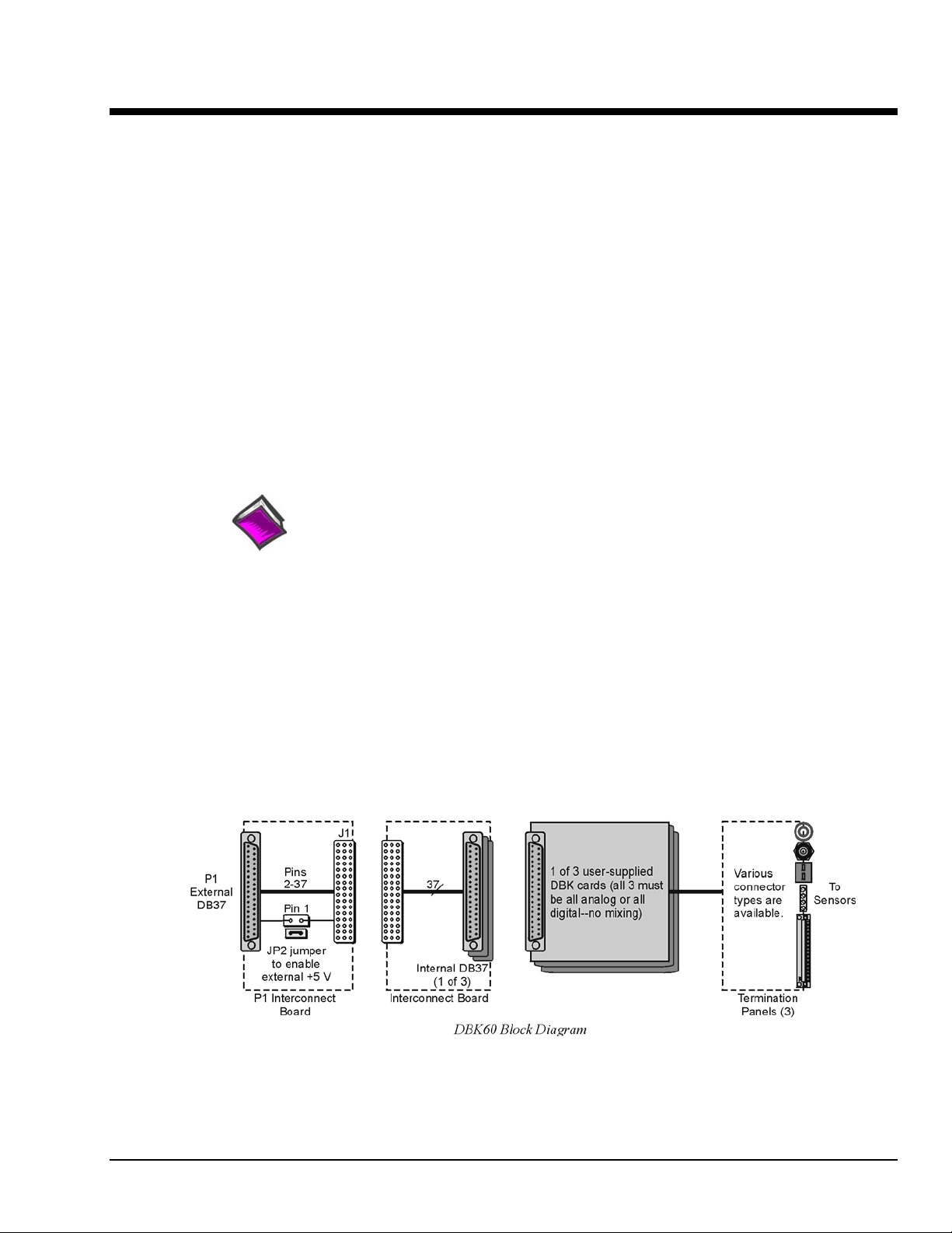
The DBK60 expansion chassis holds up to three analog DBK cards, or up to three digital DBK cards, and
provides termination panels with connectors for various sensors. Several DBK60 units can be linked
together and then to the primary acquisition device, e.g., a DaqBook, DaqBoard, or LogBook.
Splice plate kits can be used to stack multiple DBK60 units to the primary device.
DBK Option Cards and Modules 989594 DBK60, pg. 1
Page 2
The front panel has a male DB37 connector
that leads to the acquisition processor via a
CA-37-x, CA-37-xT, or equivalent cable.
The rear panel is made of three termination panels with connectors for the various sensors.
Hardware Setup
Hardware setup involves configuring the DBK60, configuring up to three DBK cards that will be used with
the module, installing the DBK cards, then connecting signal lines to the DBK60’s termination panels.
Read over the following WARNING and CAUTION, then complete the steps to successfully setup your
hardware.
WARNING
Electrical Shock Hazard! To avoid injury or equipment damage, turn off power to all
connected equipment during setup.
CAUTION
Use ESD tools, containers, and procedures during setup of DBK cards. Electrostatic
discharge can damage some of the components.
To prevent pin damage, align DBK cards with the backplane DB37 connectors before
gently pressing them together.
DBK60, pg. 2 989594 DBK Option Cards and Modules
Page 3

1 – Turn off system power and disconnect the DBK60
If the DBK60 is presently connected in a system, turn off all system devices and disconnect the
DBK60 from the system.
2 – Remove the top cover (optional)
Removing the top cover is not necessary, but it does make it easier to set the JP2 jumper in step 6.
A removed cover also allows for configuration and signal connection changes to be made to cards
later on in the procedure, after the card drawer is returned to the DBK60.
To remove the top cover, simply remove the top cover screws and slide the cover towards the
termination panels.
3 – Remove the card drawer
To remove the card drawer, refer to the A, B, and C
call-outs in the figure at the right; then complete the
corresponding steps below.
A. Remove the two screws that hold the card
drawer to the chassis.
B. Loosen the three captive thumbscrews that hold
the termination panels to the chassis.
C. Using the handle, carefully slide out the card
drawer.
4 – Remove the termination panels
Remove the two screws [two per panel] that secure each termination panel to the card drawer
(see figure).
5 – Determine the power requirements
Depending on the power needs of your system’s DBK cards, you may need to add a power card.
Refer to Power Requirements in the DBK Basics section in regard to calculating your system’s
power needs.
A. Use the DBK Power Requirements Work Table to calculate the power requirements of your
system’s DBK cards.
B. Use the Available Power Chart to determine your system’s power availability.
C. If the required power in step 5A is more than the available power in step 5B, or very close to it,
you will need to use auxiliary power. There are two DBK auxiliary power supply cards for use
in LogBook, DaqBook, and DaqBoard applications. These are the DBK32A and the DBK33.
• DBK32A – provides power at ±15 V.
• DBK33 – provides power at +5 V and ±15 V.
Three Steps for Removing the Card Drawer
DBK Option Cards and Modules 989594 DBK60, pg. 3
Page 4

6 – Configure the chassis for the power source
Use one power source, and only one power source, for cards on the P1 bus!
+5 V is selected with the DBK60’s JP2 jumper, located inside the expansion chassis on the P1
interconnect board (see the following figure for location).
±15 V is selected with two JP1 jumpers, located on the board of the primary data
acquisition device, such as a DaqBook or ISA-type DaqBoard.
DO NOT CONFUSE THESE JP1 JUMPERS WITH THE JP1 JUMPER IN THE DBK60.
A. If +5 V will be supplied from a source
header. JP2 is located on the P1 interconnect board (see figure).
outside the expansion chassis, place a jumper on DBK60’s JP2
B. If +5 V will be supplied from
a DBK33 power card inside the expansion chassis, remove the jumper
from the JP2 header (located on the P1 interconnect board).
C. If using a DBK32A or DBK33 power card anywhere in the system, remove the +15 V and -15 V
jumpers from JP1 on the primary data acquisition device, such as a DaqBook or ISA-type
DaqBoard. DO NOT CONFUSE THESE JP1 JUMPERS WITH THE JP1 JUMPER IN THE DBK60.
Reference Notes:
Refer to the DBK32A or DBK33 sections, if applicable.
DBK60, pg. 4 989594 DBK Option Cards and Modules
Page 5

7 – Install a power card, if needed
If you determined [in step 5] that additional power is needed, add a DBK32A or DBK33 power card to the
acquisition processor chassis, or to the DBK60 expansion chassis.
To install a power card in a DBK60 complete steps 7A and 7B. Refer to the previous figure as needed.
A. Carefully align the power card’s DB37 connector with a DB37 connector on DBK60’s P1 interconnect
board and gently press the power card to establish a complete and solid connection.
B. Use two screws to secure the power card to DBK60’s card drawer standoffs.
8 – Configure the DBK cards
Configure channel addresses that are unique to each card; i.e., do not duplicate addresses. Some cards make
use of jumpers for address configuration, while others make use of DIP switches.
Reference Note:
Refer to the appropriate DBK document modules in regard to specific DBK configuration.
9 – Install the DBK cards
You cannot mix analog and digital DBK cards in the DBK60; in other words, use all analog or
all digital, but not both.
A. Carefully align the DBK card’s DB37 connector with a DB37 connector on the interconnect board and
gently press gently press the DBK card to establish a complete and solid connection (see previous figure).
B. Use two screws to secure the DBK card to the standoffs on the DBK60 card drawer (see previous figure).
C. Repeat installation steps 9A and 9B for additional DBK cards, as applicable. Be sure that all cards to be
installed are analog, or all digital. Analog and digital can not be mixed within a DBK60.
10 – Connect the internal signals
Connect signal inputs from DBK cards to the termination panels. DBK cards connect to the termination
panels in various ways. Refer to the following figure and to the specific DBK document modules as needed.
• Single-ended connections use analog common.
• Differential connections require the proper polarity, typically red-to-red for high (+) and
black-to-black for low (-).
• For thermocouples, red is generally the low side. The T/C connector and wire type must match the T/C
type used.
11 – Install the termination panels
Mount the termination panels to the card drawer. Use two screws to secure each panel.
Refer to the DBK60 Hardware Setup figure.
DBK Option Cards and Modules 989594 DBK60, pg. 5
Page 6

12 – Install the card drawer
A. Hold the card drawer by its handle and tilt it up slightly. Place it on the bottom track of the DBK60.
B. Carefully slide the card drawer into the chassis. When it engages the bottom track, level the card drawer
and continue inserting it until it engages with the P1 interconnect board.
C. Tighten the three captive thumbscrews [on the termination panels] into the chassis
(see DBK60 Hardware Setup figure).
D. Install the two bottom screws that hold the card drawer to the chassis.
13 – Connect external signals
Connect signal inputs from the sensors to termination panels.
14 – Install the top cover
If the top cover had been removed, slide it back into position and secure the cover with the two
top cover screws.
15 – Connect the DBK60 to the rest of your acquisition system
A. If using analog DBK cards, connect the DBK60 to P1 of the system.
B. If using digital DBK cards, connect the DBK60’s P1 to a P2 port of the system.
Then Re-label the DBK60 front panel connector “P2.”
16 – Turn on system power and check operation
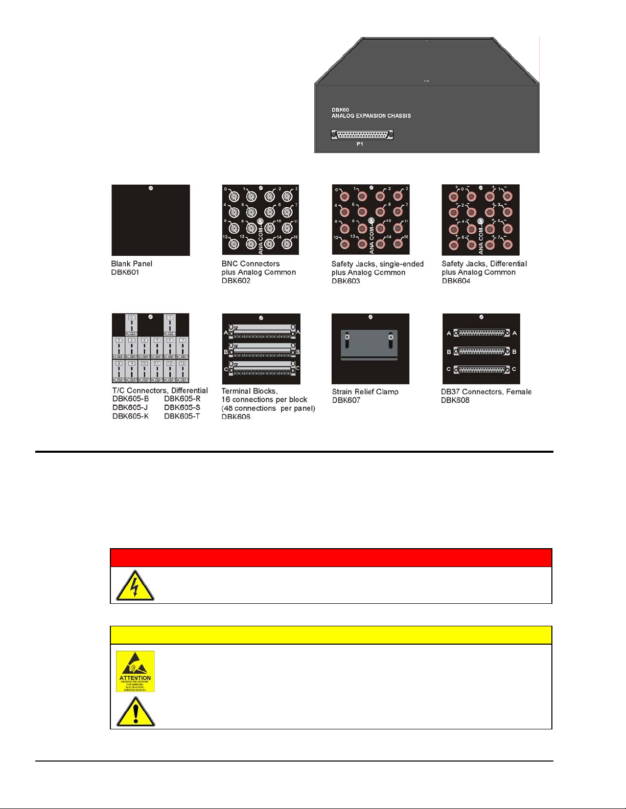
DBK60 - Specifications
Description: DBK Card Expansion chassis accommodating 3 DBK cards, configurable power
capability. Selection of 7 termination panels to allow custom user input connection.
Capacity: Accommodates any 3 DBK expansion cards.
Analog and Digital DBK cards cannot be mixed within a single DBK60 enclosure.
Material: Aluminum and Steel
Finish: Black, powder-coated
Dimensions: 280 mm x 330 mm x 89 mm (11” x 13” x 3.5”)
Weight: 3.08 kg empty (7 lbs.); cards .25 to .75 kg each (8 to 12 oz)
DBK60, pg. 6 989594 DBK Option Cards and Modules
 Loading...