

Page 1
DBK52 14-Channel Thermocouple Input Module
Overview …… 1
Hardware Setup …… 2
Module Connection …… 2
Module Configuration …… 3
DaqBook/100 Series & /200 Series and DaqBoard [ISA type] Configuration …… 3
DaqBook/2000 Series and DaqBoard/2000 Series Configuration …… 3
Software Setup …… 4
DBK52 – Specifications …… 4
Reference Notes:
o Chapter 2 includes pinouts for P1, P2, P3, and P4. Refer to pinouts applicable to
Overview
The DBK52 provides the ability to scan and input thermocouple data for various computer-based
temperature-monitoring systems. Features include:
• Each DBK52 can connect up to 14 thermocouples. Up to 16 DBK52s may attach to a single
your system, as needed.
o In regard to calculating system power requirements, refer to DBK Basics located
near the front of this manual.
DaqView Users: When DBK52 is used with /2000 Series Devices, the Internal Clock Speed
should be set to 100 kHz as described in Chapter 3, DBK Setup in DaqView.
LogBook or Daq Device to measure a maximum of 224 (16 × 14) temperatures.
• Standard, miniature jacks can connect to all T/C types.
• Onboard cold junction sensor (CJS) circuitry is accessible via a built-in channel to the system.
• A built-in short-to-ground channel back to the system eliminates offset errors via software.
• RC low-pass input filters reject high frequency noise for thermocouple shields.
• An external analog-common access jack provides a bias-current return path for differential
signal inputs.
• An onboard programmable gain amplifier supports most thermocouple types and temperature
ranges.
• Software-based linearization (in LogView and DaqView) converts analog signals into
temperature values.
Reference Note:
In regard to Daq devices, related material for programmers is included in the separate
Programmer’s Manual (p/n 1008-0901).
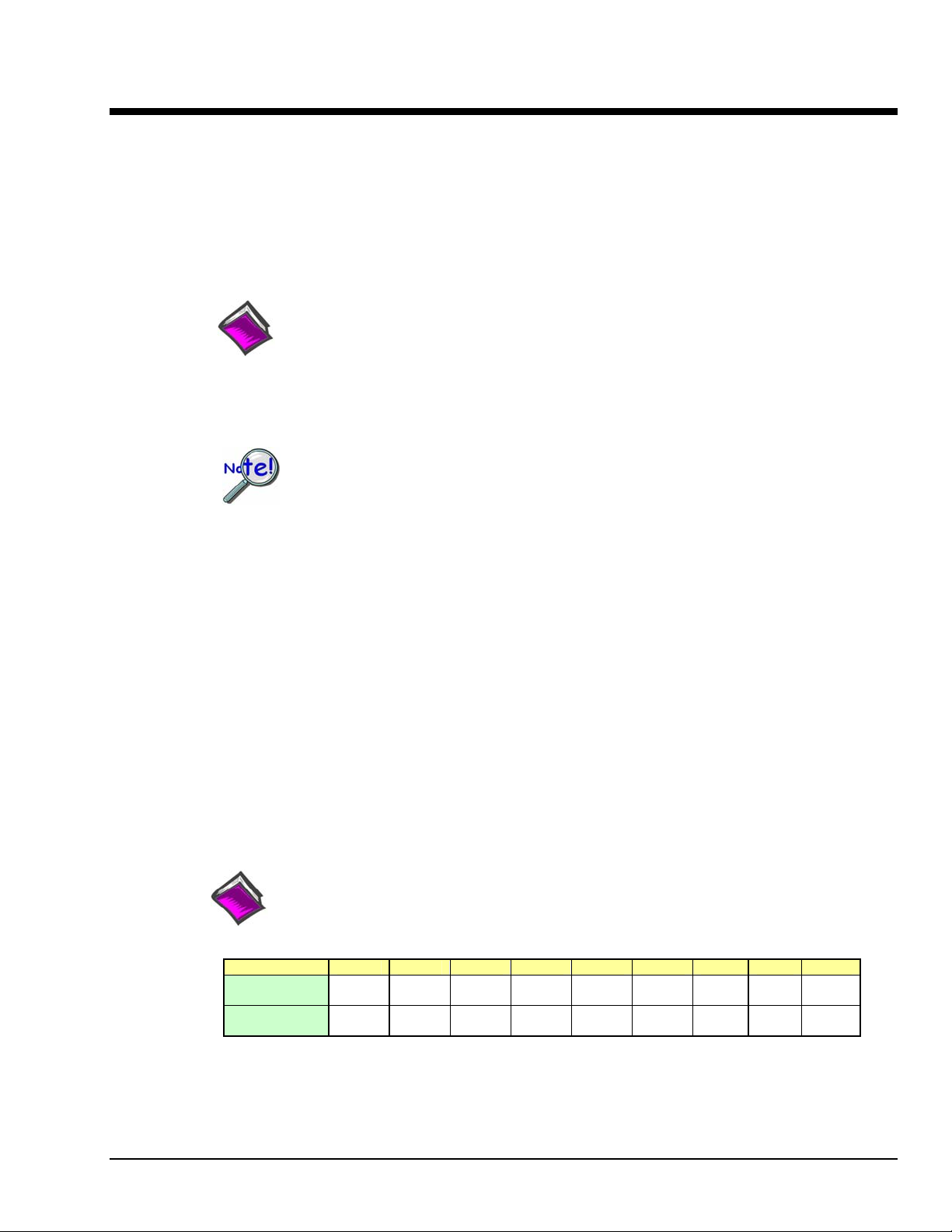
The following table shows the temperature range for each thermocouple type.
T/C Type J K T E N28 N14 S R B
Temperature
Range °C
Temperature
Range °F
-200 to
760
-328 to
1400
-200 to
1260
-328 to
2300
-200 to
400
-328 to
752
-270 to
1000
-454 to
1832
-270 to
400
-454 to
752
0 to
1300
32 to
2372
0 to
1780
32 to
3236
0 to
1780
32 to
3236
0 to
1820
32 to
3308
Thermocouple accuracy depends on the thermocouple itself, the cold-junction sensor, A/D conversion, and
linearization. The DBK52, LogBook, and Daq device systems use quality components and software
compensation to minimize error from these sources. Systems achieve a ±1°C CJS accuracy that contributes
to the overall accuracy. When the software is calibrated, gain and offset errors are virtually eliminated.
The DBK52’s built-in auto-zero channel dynamically eliminates any other system offset-errors.
DBK Option Cards and Modules 989594 DBK52, pg. 1
Page 2
True differential measurements of T/Cs require bias-current referenced to the analog common. Resistors
from each input T/C are connected to the analog common. Filter capacitors across each input operate with
input protection resistors to form a single-pole RC low-pass filter.
Hardware Setup
Module Connection
The DBK52 has miniature T/C jacks to connect different types of thermocouples and an analog-ground
access point. Connections are provided for 14 thermocouples. Thermocouple polarities must be
observed. Thermocouple types J, K, T, E, N28, N14, S, R and B are supported by the LogView or
DaqView software and may be connected to DBK52 board channels CH2 through CH15.
Note: CH0 is reserved for the cold-junction compensation sensor (factory installed).
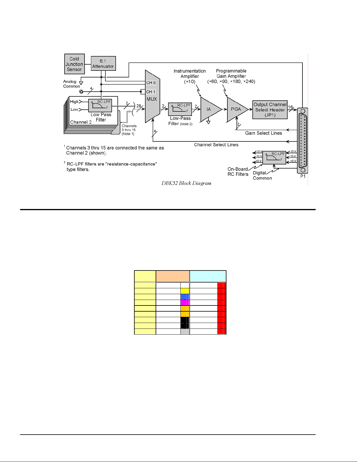
Thermocouple wire is standardized and color-coded as shown in the table. T/Cs have a very small output.
Long T/C leads can pickup lots of noise. Use shielding as needed, and average several readings in
software to minimize noise effects.
T/C
Type
J White Red
K Yellow Red
T Blue Red
E Violet Red
N28 Orange Red
N14 Orange Red
S Black Red
R Black Red
B Gray Red
(+) Lead to
Channel-Hi
(-) Lead to
Channel-Lo
CH1 is permanently shorted to allow software-driven auto-zero to compensate for
temperature drift.
After all connections are in place, secure wires to captive areas (pre-drilled holes) at the rear edge of the
board. Nylon tie wraps (not included) work well for this purpose.
DBK52, pg. 2 989594 DBK Option Cards and Modules
Page 3

Module Configuration
Up to 16 DBK52s may be connected to a LogBook or a Daq Device. As a daisy-chain
interface, each module must appear unique. Each module uses a different analog input
channel. To configure the module:
1. Assign a channel number to the module. The assigned number must
not be used by any other DBK card or module.
2. Locate the 16×2-pin header near the front of the board labeled JP1, and
place the jumper on the LogBook or Daq Device channel you wish to
use. There are 16 jumper locations on this header labeled CH0 through
CH15. Only one jumper setting is used on a single module; no other
module in a common daisy-chain can use the same jumper setting.
DaqBook/100 Series & /200 Series and DaqBoard [ISA type] Configuration
Three setup steps and needed to configure DaqBooks/100 Series & /200 Series devices and
DaqBoards [ISA type] for a DBK52.
1. If not using auxiliary power, place the JP1 jumper in the Analog Option Card Use (expanded
analog) mode.
Note:
These jumpers do not
apply to /2000 Series
devices.
To power the interface circuitry of the DBK52 via the internal ±15 VDC power supply,
JP1 must be set to “Analog Option Card Use.” However, if using auxiliary power, e.g.,
the DBK32A or the DBK33, you must remove both JP1 jumpers. Refer to
Power Requirements in the DBK Basics section and to the DBK32A and DBK33
sections for additional information, as applicable.
2. For DaqBook/100, DaqBook/112 and DaqBook/120 only, place the JP3 jumper in
bipolar mode.
3. For DaqBook/100, DaqBook/112 and DaqBook/120 only, place the JP4 jumper in
single-ended mode.
Note: The DaqBook/200 Series devices and DaqBoards do not have a JP4. The single-ended or differential
choice is made via software configuration commands.
DaqBook/2000 Series and DaqBoard/2000 Series Configuration
No jumper configurations are required for the /2000 series devices.
DBK Option Cards and Modules 989594 DBK52, pg. 3
Page 4

Software Setup
Reference Notes:
o DaqView users - Refer to Chapter 3, DBK Setup in DaqView.
o LogView users - Refer to Chapter 4, DBK Setup in LogView.
o DBK52 Calibration Disk – Each DBK52 card is shipped with a calibration disk with constants
used to correct gain and offset errors inherent in the hardware. This calibration is done
automatically by DaqView and LogView. Refer to the readme.txt file on the disk.
DaqView Users: When DBK52 is used with /2000 Series Devices, the Internal Clock Speed should be
set to 100 kHz as described in Chapter 4, DBK Setup in DaqView.
The DBK52 selection allows the user to define the thermocouple types by using the Type column of the
analog input spreadsheet.
Each DBK52 card is shipped with a calibration disk with constants used to correct gain and offset errors
inherent in the hardware. This gain and offset calibration is done automatically by DaqView and
LogView. See the DBK52 readme.txt file on the disk shipped with the board for details on creating this
file.
DBK52 - Specifications
Name/Function: Thermocouple Input Module
Connectors:
DB37 male, mates with P1.
Thermocouples attach directly to on-board jacks.
Thermocouple Types: J, K, S, T, E, B, R, N
Gain Ranges: ×60, ×90, ×180, ×240
Inputs:
14 differential thermocouples
1 cold-junction compensation
1 auto zero
Cold Junction Sensor Output: 100 mV/°C
Voltage Ranges/Gains:
Input Impedance: 20 kΩ
Input RC Filter -3 dB Frequency: 15.9 kHz
Gain Accuracy:
Uncalibrated: 0.15%
Calibrated: 0.02%
Maximum Input Voltage: 35 VDC
CMRR (Input Stage): 110 dB type DC to 60 Hz
Offset: Software compensated
Type/Range/Accuracy/Resolution: refer to the
following table
0 to 80 mV ×60
0 to 50 mV ×90
0 to 25 mV ×180
0 to 20 mV ×240
0 to ±10 mVDC
Thermocouple Reference
Range Accuracy Resolution
Type Min Max (<0°C) (>0°C)
J
K
T
E
N28
N14
S
R
B
-200°C 760°C 0.6°C 0.6°C 1.2°C 0.5°C 0.1°C 0.1°C
-200°C 1260°C 1.6°C 1.0°C 1.1°C 0.8°C 0.1°C 0.1°C
-200°C 400°C 1.4°C 0.8°C 0.8°C 0.3°C 0.1°C 0.1°C
-270°C 1000°C 1.4°C 0.9°C 1.6°C 0.7°C 0.1°C 0.1°C
-270°C 400°C 0.8°C 0.8°C 1.0°C 1.0°C 0.1°C 0.1°C
0°C 1300°C
0°C 1780°C
0°C 1780°C
0°C 1820°C
— 1.0°C — 5.0°C — 5.0°C
— 1.6°C — 1.3°C — 0.1°C
— 1.6°C — 1.7°C — 0.1°C
— 1.8°C — 1.5°C — 0.1°C
12-bit
<0°C
12-bit
>0°C
16-bit
<0°C
16-bit
>0°C
DBK52, pg. 4 989594 DBK Option Cards and Modules
 Loading...