

Page 1
DBK50 and DBK51 8-Channel Isolated Voltage Input Modules
Overview …… 1
Input Attenuation/Gain Factors …… 2
Hardware Setup …… 2
Signal-to-Module Connection …… 2
Module Configuration …… 2
DaqBook/100 Series & /200 Series and DaqBoard [ISA type] Configuration …… 3
DaqBook/2000 Series and DaqBoard/2000 Series Configuration …… 4
Software Setup …… 4
DBK50 and DBK51 – Specifications …… 4
Reference Notes:
o Chapter 2 includes pinouts for P1, P2, P3, and P4. Refer to pinouts applicable to your
Overview
system, as needed.
o In regard to calculating system power requirements, refer to DBK Basics located near
the front of this manual.
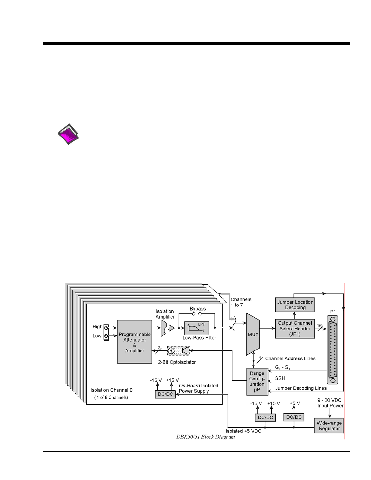
Except for their ranges, the DBK50 (high-voltage) and the DBK51 (low-voltage) are identical. Both have
eight channels isolated from themselves (750 V) and from the LogBook or Daq Device analog common
(1250 V). Each channel’s input impedance is over 10 M
measured. Voltages can be read from DC to more than 20 kHz. One of three voltage ranges can be chosen
via software:
• for DBK50: ±10 V, ±100 V, or ±300 V.
• for DBK51: ±100 mV, ±1 V, or ±10 V.
Ω to minimize loading of the circuit being
With standard plug-in attenuator assemblies, the voltage ranges are interch angeable. The gain or
attenuation factor depends on the range, but the full-scale output for any range is +5 V.
Note: A fourth “range” delivers a shorted input voltage reading to allow offset compensation in some
applications.
DBK Option Cards and Modules 989594 DBK50 and DBK51, pg. 1
Page 2
Input Attenuation/Gain Factors
Gain and attenuation may be calculated using the formula:
where: K is the attenuation or gain factor (the values of K for
available voltage ranges are given in the table).
Vin is the voltage applied to the module input channel.
Vout is the amplified or attenuated voltage from the module
output back to the main unit.
Hardware Setup
Signal-to-Module Connection
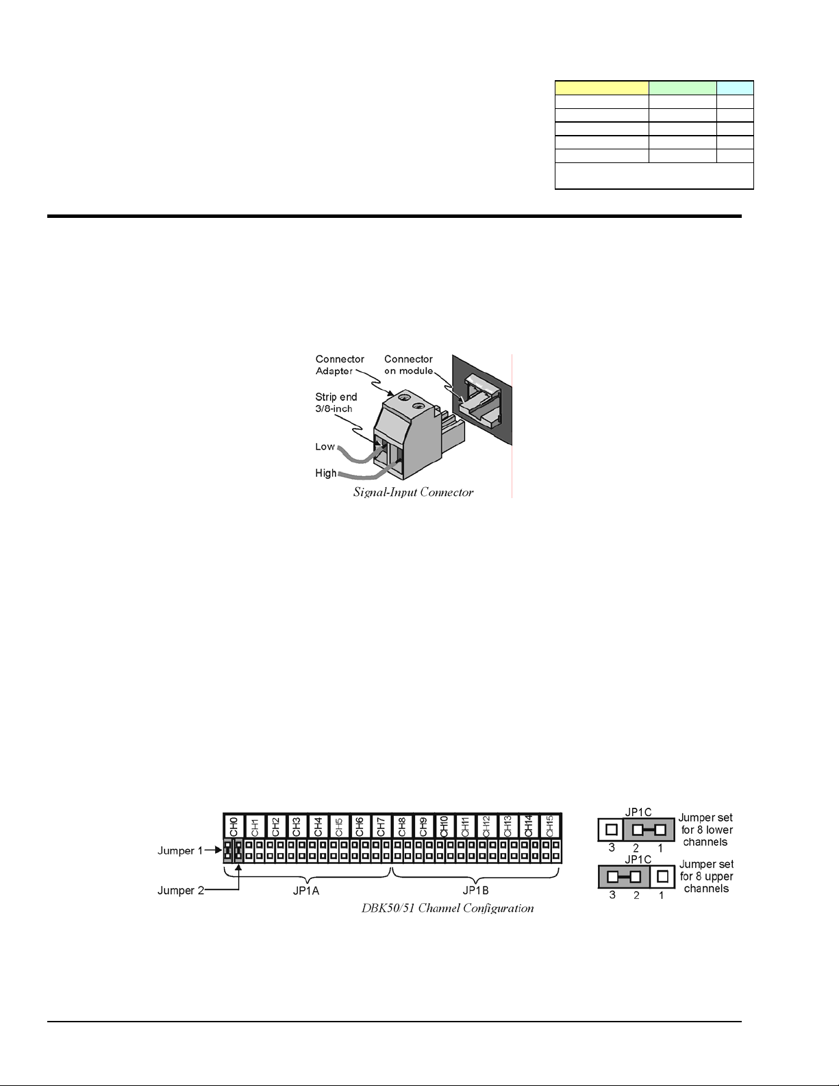
The DBK50/51 rear panel has 8 plug-in screw terminals for easy access to the 8 analog input channels.
There is a high (right side) and a low (left side) terminal in each pair to maintain consistent polarity (see
figure). For AC signals, the polarity is arbitrary unless multiple signals must maintain their phase
relationship.
K = Vin / Vout
Input Range Function K
300 V Range Attenuates 60
100 V Range Attenuates 20
10 V Range Attenuates 2
1 V Range Amplifies 0.2
100 mV Range Amplifies 0.02
Note: not all input ranges are
available on a single unit.
Module Configuration
Factory Default: Low-pass filter – Enabled
Several jumpers must be set on the DBK50 and DBK51 to match your application:
• 2 jumpers on JP1A or JP1B to select the main channel to use (see following figure).
• 1 jumper on JP1C for upper or lower sub channels
• 1 jumper on JPn02 to use or bypass the low-pass filter—one for each channel number (n)
The main output channel is one of the 16 primary data acquisition device [LogBook or Daq device]
channels. Each DBK50 [and DBK51] has 8 input channels and can be set to an upper or lower subchannel that allows 2 modules to share a single LogBook or Daq device channel. Thus, a fully-populated
system can have 256 input channels.
After determining a main channel number for the module, set two jumpers on JP1A or JP1B for the desired
channel. The two jumpers must be used side-by-side on the selected channel. This is illustrated for
channel 0 in the following figure. Next, set the JP1C jumper for the eight upper or eight lower subchannels. Note that two modules may share the same main channel if one is set to the upper sub channel
and the other set to the lower sub channel.
Each of the 8 input channels has a 3-pole low-pass filter that may be manually selected or bypassed by
positioning 2 shunt jumpers on 2×2 headers for each channel. Orient the jumpers parallel/horizontal
(enable) or perpendicular/vertical (bypass) to the header label (JP102 to JP802 for each of 8 channels).
The following figure can be used for orientation.
DBK50 and DBK51, pg. 2 989594 DBK Option Cards and Modules
Page 3

D
Channel Filter Jumper Settings for DBK50 and DBK51
The low-pass filters have a default corner frequency of 3.5 Hz when the jumpers are in the LPF-selected
positions. This frequency may be readily changed by installing a different value of SIP resistor network in
the 6-pin SIP socket of each filter section. Each channel has its own SIP located next to the channel filter
bypass jumper and labeled RN(1-8)01A. The table lists values of common networks and their corner
frequencies.
Corner Frequency R-SIP Bournes Part #
7500 Hz
3500 Hz
1750 Hz
750 Hz
350 Hz
175 Hz
75 Hz
35 Hz
17.5 Hz
7.5 Hz
3.5 Hz
47 Ω
100 Ω
200 Ω
470 Ω
1 k Ω
2 k Ω
4.7 k Ω
10 k Ω
20 k Ω
47 k Ω
100k Ω
4606M-102-470
4606M-102-101
4606M-102-201
4606M-102-471
4606M-102-102
4606M-102-208
4606M-102-208
4606M-102-103
4606M-102-203
4606M-102-473
4606M-102-104
DaqBook/100 Series & /200 Series and DaqBoard [ISA type] Configuration
Several setup steps in DaqBook/100 Series & /200 Series devices and DaqBoards [ISA type] are required
to use a DBK50 or DBK51 module in a system.
1. If not using auxiliary power, set the JP1 jumper [in the DaqBook/100 Series & /200 Series
devices or ISA-Type DaqBoard] to the Analog Option Card Use, also referred to as the
expanded analog mode.
JP1
-15 V
-OCTOUT
-OCLKIN
Analog Option
+15 V
Card Use
JP2
DAC 1 - EXT
DAC 1 - INT
SSH
DAC 0 - INT
DAC 0 - EXT
JP3 JP4
UNI-
BI-
Bipolar
aqBook/DaqB oard Jumpers f or DB K50 /51
Single-Ended
SE
16CH
DIFF
8CH
DBK Option Cards and Modules 989594 DBK50 and DBK51, pg. 3
Page 4

To power the interface circuitry of the DBK50 [or DBK51] via the internal ±15 VDC
power supply, JP1 must be set to “Analog Option Card Use.” However, if using
auxiliary power, e.g. the DBK32A or the DBK33, you must remove both JP1 jumpers.
Refer to Power Requirements in the DBK Basics section and to the DBK32A and DBK33
sections as applicable.
When using the SSH output, do not use an external voltage reference for DAC1.
CAUTION
Applying an external voltage reference for DAC1, when using the SSH output, will
result in equipment damage due to a conflict on P1, pin #26.
2. Place the JP2 jumper in the SSH position.
3. For DaqBook/100, DaqBook /112 and DaqBook /120 only, place the JP3 jumpers in
bipolar mode.
4. For DaqBook/100, DaqBook/112 and DaqBook/120 only, place the JP4 jumpers in
single-ended mode.
DaqBook/2000 Series and DaqBoard/2000 Series Configuration
No jumper configurations are required for these /2000 series devices.
Software Setup
Reference Notes:
o DaqView users - Refer to chapter 3, DBK Setup in DaqView.
o LogView users - Refer to chapter 4, DBK Setup in LogView.
DaqBooks/100 Series & /200 Series devices and DaqBoards [ISA type] must have the
Simultaneous Sample and Hold (SSH) jumper in place when using a DBK50 or DBK51.
DaqView will remind you of this when you exit Hardware Setup with a DBK50 or DBK51
selected.
DBK50 and DBK51 – Specifications
Name/Function: 8-Ch. Isolated Voltage Input Module
Connectors: Male DB37, mates with P1
Inputs: Removable screw terminals
Number of Channels: 8, individually isolated
Isolation:
Channel-to-Channel: 500 V
Channel-to-System: 500 V
Input Impedance:
DBK50: 1 MΩ
DBK51: >10 MΩ
Bipolar Input Ranges:
DBK50: ±10 V, ±100 V, ±300 V
DBK51: ±100 mV, ±1 V, ±10 V
Output Voltage Range: ±5 VDC
Accuracy:
Without Offset Correction: 1% of range
With Offset Correction: 0.2% of range
Offset: ±50 mV max
Noise:
With Low-Pass Filter: <5 mV peak to peak
Without Low-Pass Filter: <50 mV peak to peak
Temperature Coefficient: 0.2 mV/°C
Attenuation Ratios: V
DBK50:
10 V K = 2.0 gain = 0.5
100 V K = 20.0 gain = 0.05
300 V K = 60.0 gain = 0.0166
DBK51:
0.1 V K = 0.02 gain = 50
1 V K = 0.2 gain = 5
10 V K = 2.0 gain = 0.5
Bandwidth: 20 kHz (LPF bypassed)
Low-Pass Filter: Factory installed 3-pole, 3.5Hz
(bypass or user-set)
Operating Power Voltage Range: +9 to +20 VDC
Module Power Requirements: 7.5 W
AC Adapter Rating: 15 VDC @ 0.9 A
Dimensions: 285 mm W x 221 mm D x 36 mm H
(11” x 8.5” x 1.375”)
Weight: 1.7 kg (4 lbs)
= Vin / K
out
DBK50 and DBK51, pg. 4 989594 DBK Option Cards and Modules
 Loading...