

Page 1
DBK44 2-Channel 5B Signal-Conditioning Card
Overview ….. 1
Hardware Setup ….. 2
Power Considerations ….. 2
Card Configuration ….. 3
5B Module Connection ….. 3
Terminal Block Connection ….. 4
P1 Connection ….. 4
CE Compliance ….. 5
DaqBook/100 Series & /200 Series and DaqBoard [ISA type] Configuration …… 5
DaqBook/2000 Series and DaqBoard/2000 Series Configuration …… 6
Software Setup ….. 6
mx+b Values for 5B Modules ….. 7
DBK44 – Specifications ….. 7
Reference Notes:
o Chapter 2 includes pinouts for P1, P2, P3, and P4. Refer to pinouts applicable to your
system, as needed.
o In regard to calculating system power requirements, refer to DBK Basics located near
the front of this manual.
Reference Note:
Users of the DBK44 signal-conditioning card may be interested in the DBK207 and DBK207/CJC,
Carrier Boards for 5B Compatible Analog I/O Modules. Each DBK207 and DBK207/CJC board
includes a 100-pin P4 connector for DaqBoard/2000 Series and /2000c Series compatibility, two P1
connectors for analog expansion, a power connection terminal, and 16 signal terminal blocks. In
addition, the DBK207/CJC board includes CJC (Cold Junction Compensation) for thermocouple
applications. DBK207 and DBK207/CJC can be mounted in Nema-type panels.
Overview
The 2-channel DBK44 allows LogBook or Daq device systems to use any combination of 5B signalconditioning modules. 5B modules can accommodate a variety of signals (low-level thermocouple signals
to strain-gage signals, etc). Configuration options are flexible. You can select the type of signal attached
to each channel. One LogBook or Daq device can support up to 128 DBK44 cards, providing up to 256
isolated, analog input channels.
DBK Option Cards and Modules 877095 DBK44, pg. 1
Page 2
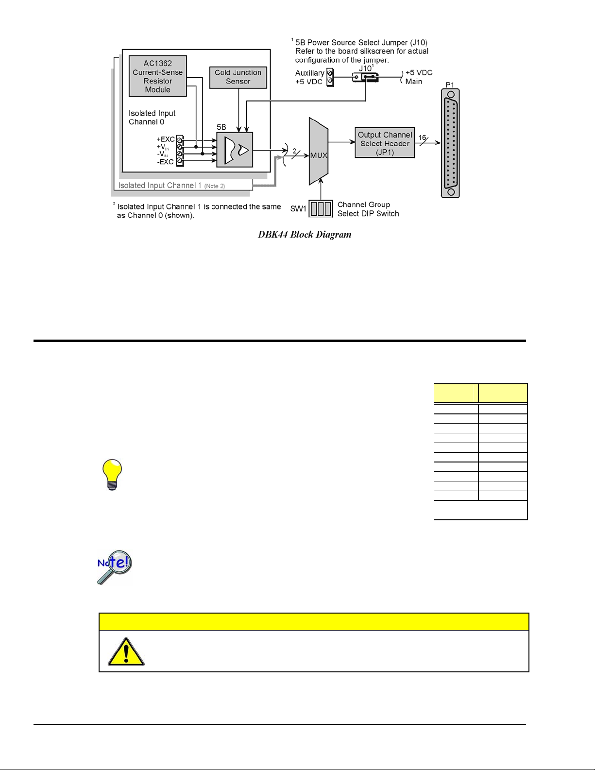
The LogBook or Daq device scans the DBK44’s channels at the same 10 µs/channel rate as other DBKs
(256 scans in 2.56 ms in a full system). Each user-installed 5B module offers 500 V isolation from the
system and between channels. The DBK44 has convenient screw-terminal blocks for signal inputs and
excitation outputs (for use with a strain gage or RTD). Cold junction compensators (CJC) are installed and
ready to use with thermocouple 5B modules. Sockets are provided for AC1362 current-sense resistor
modules.
Hardware Setup
Power Considerations
The DBK44 requires +5 and ±15 VDC from a LogBook, Daq device P1
connector, or auxiliary power supply. In some applications, the DBK44 can draw
enough power from the LogBook’s internal power supply via the P1 connector.
However, the 5B power requirements (+5 VDC only) may be greater than the
LogBook or DaqBook/DaqBoard can provide (see table).
For applications with more than 4 channels, it may be better to use
the DBK42 instead of the DBK44. The DBK42 is a 16-channel
module with a built-in power supply.
External power can be obtained from any regulated 5 V source or from a
TR-4 power supply. External power attaches to the DBK44 via onboard
screw-terminal connections (the Auxiliary Power Input J9 Combicon
terminal at the rear of the board).
5B
Model
5B30 30 mA
5B31 30 mA
5B32 30 mA
5B34 30 mA
5B37 30 mA
5B38 200 mA
5B39 *170 mA
5B40 30 mA
5B41 30 mA
5B47 30 mA
* Maximum output load
resistance is 750 Ω
Current
Required
The 5B38 series strain-gage modules with excitation output require an external power
source. Auxiliary power is also necessary in systems equipped with more than one DBK44.
Prior to using auxiliary power, you must select AUXL on the Power Source Select Jumper
(J10).
CAUTION
DBK44, pg. 2 877095 DBK Option Cards and Modules
Auxiliary power input must not exceed +5 VDC. DBK44 does not regulate auxiliary
power input.
Page 3
Card Configuration
Up to 128 DBK44s may connect to a LogBook or a Daq device system. Since this is a
daisy-chain interface, each module must appear unique and use a different analog input
channel. To configure the card’s channel, you must set the JP1 jumper and the
SW1 DIP switch to your chosen channel as follows.
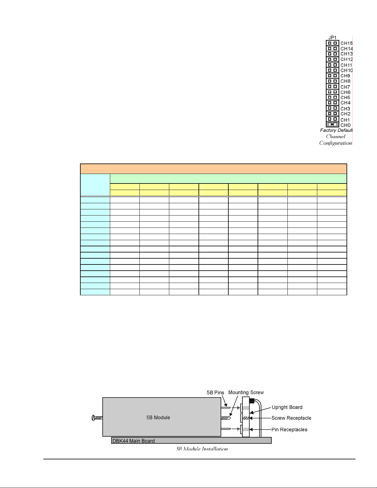
1. Locate the 16×2-pin header (labeled JP1) near the front of the card. Note the
16 jumper locations labeled CH0 through CH15 to match the main channel.
2. Place the JP1 jumper on the channel you wish to use. Only one jumper is
used per card, but up to 8 DBK44s can occupy one main channel and use the
same JP1 setting (but with different SW1 settings).
3. Locate the SW1 DIP switch that serves as a channel group select switch and
can distinguish up to 8 cards on a channel.
4. Place the 3 mini switches (CBA) in the position that corresponds to your
chosen channel as shown in the table below. For each JP1 setting, there
are 8 possible SW1 settings to allow two input channels per card).
Channel Pair Determined by JP1 and SW1
JP1
Jumper
CH0 16-17 18-19 20-21 22-23 24-25 26-27 28-29 30-31
CH1 32-33 34-35 36-37 38-39 40-41 42-43 44-45 46-47
CH2 48-49 50-51 52-53 54-55 56-57 58-59 60-61 62-63
CH3 64-65 66-67 68-69 70-71 72-73 74-75 76-77 78-79
CH4 80-81 82-83 84-85 86-87 88-89 90-91 92-93 94-95
CH5 96-97 98-99 100-101 102-103 104-105 106-107 108-109 110-111
CH6 112-113 114-115 116-117 118-119 120-121 122-123 124-125 126-127
CH7 128-129 130-131 132-133 134-135 136-137 138-139 140-141 142-143
CH8 144-145 146-147 148-149 150-151 152-153 154-155 156-157 158-159
CH9 160-161 162-163 164-165 166-167 168-169 170-171 172-173 174-175
CH10 176-177 178-179 180-181 182-183 184-185 186-187 188-189 190-191
CH11 192-193 194-195 196-197 198-199 200-201 202-203 204-205 206-207
CH12 208-209 210-211 212-213 214-215 216-217 218-219 220-221 222-223
CH13 224-225 226-227 228-229 230-231 232-233 234-235 236-237 238-239
CH14 240-241 242-243 244-245 246-247 248-249 250-251 252-253 254-255
CH15 256-257 258-259 260-261 262-263 264-265 266-267 268-269 270-271
CBA CBA CBA CBA CBA CBA CBA CBA
0 0 0 0 0 1 0 1 0 0 1 1 1 0 0 1 0 1 11 0 1 1 1
5B Module Connection
Each input of the DBK44 is processed through a user-installed 5B signal-conditioning module. Different
5B modules are used with different transducer and signal sources. To install the modules:
1. Remove all power from the DBK44.
SW1 DIP Switch Setting
2. Match the footprint of the module with the footprint on the circuit board (see figure).
3. Gently place the module into the footprint, and screw it down.
4. Record the channel the module was placed in.
DBK Option Cards and Modules 877095 DBK44, pg. 3
Page 4

When installing current input modules (SC-5B32 series), be sure to install the current-sense resistor
(SC-AC-1362 shipped with the SC-5B32) in the resistor socket (J4 for ch 0, J3 for ch 1) near the input
screw-terminal block (see figure).
Terminal Block Connection
Input signals (and excitation leads) must be wired to the DBK44 via the 4-contact terminal blocks at the
end of the card. These terminal blocks connect internally to their corresponding signal conditioning
module. The terminal blocks accept up to 14-gage wire into quick-connect screw terminals that are labeled
as to their function. Each type of input signal or transducer (such as a thermocouple or strain gage) should
be wired to its terminal block as shown in the figure. Wiring is shown for RTDs, thermocouples, 20 mA
circuits, mV/V connections, and for full- and half-bridge strain gages.
Shock Hazard! De-energize circuits connected to the DBK44 before changing the
wiring or configuration. The DBK44 is designed to sense signals that may carry
dangerous voltages.
WARNING
P1 Connection
Reference Notes:
Chapter 2 includes pinouts for P1, P2, P3, and P4. Refer to pinouts applicable to your
system, as needed.
The DBK44 attaches to the LogBook’s or Daq Device’s P1 analog I/O connector. Connect the CA-37-x
accessory ribbon cable (with x indicating the number of cards to be connected) from P1 to the DB37
connector at the end of the DBK44 card.
DBK44, pg. 4 877095 DBK Option Cards and Modules
Page 5

Note: A series of interface cables are available to connect up to 128 DBK44s. You can also use a DBK41
DBK44 can be connected to the P1 connector of DBK200, DBK201, DBK202, or DBK203. Connect the
CA-37-x accessory ribbon cable (with x indicating the number of cards to be connected) from P1 to the
DB37 connector at the end of the DBK44 card.
Note: Interface cables are available to connect up to 128 DBK44s.
CE Compliance
10-slot expansion chassis.
Reference Notes:
Should your data acquisition system need to comply with CE standards, refer to
the CE Compliance section of the chapter Signal Management.
DaqBook/100 Series & /200 Series and DaqBoard [ISA type] Configuration
The DBK44 requires two setup steps in DaqBooks/100 Series & /200 Series devices and
DaqBoards [ISA type]—jumpers JP1 and JP4.
1. If not using auxiliary power, ensure the JP1 jumper is configured for Analog Option Card Use
(expanded analog mode).
Note: This default position is necessary to power the interface circuitry of the DBK44 via the
internal ±15 VDC power supply. If using auxiliary power from a DBK32A or DBK33 card,
you must remove both JP1 jumpers. Refer to Power Requirements in the DBK Basics section.
Also refer to the DBK32A and DBK33 sections as applicable.
2. For DaqBook/100, /112, and /120 only, place the JP4 jumper in the DaqBook or DaqBoard [ISA
type] in single-ended mode. Note that analog expansion cards convert all input signals to single-
ended voltages referenced to analog common.
Note: The configuration of the JP3 jumper depends on the output range of the 5B module. For
example, a 5B31 volt input module has an output range of -5 to +5 V in bipolar mode. A
5B47 T/C module (output 0 to +5 V) could use bipolar mode, but unipolar mode is more
appropriate.
DBK Option Cards and Modules 877095 DBK44, pg. 5
Page 6

DaqBook/2000 Series and DaqBoard/2000 Series Configuration
No jumper configurations are required for these 2000 series devices.
Software Setup
Reference Notes:
o DaqView users - Refer to chapter 3, DBK Setup in DaqView.
o LogView users - Refer to chapter 4, DBK Setup in LogView.
DBK44, pg. 6 877095 DBK Option Cards and Modules
Page 7

mx+b Values for 5B Modules
The mx+b calculations for most 5B modules are included within LogView software. The table shows the
m and b values for various 5B modules.
5B Module m Value b Value Engineering
Isolated Voltage Input (5 V Current Requirement, 30 mA)
SC-5B31-01 1/5 0 mV, V
SC-5B31-02 1 0 mV, V
SC-5B31-03 2 0 mV, V
SC-5B31-04 2/5 -1 mV, V
SC-5B31-05 2 -5 mV, V
SC-5B31-06 4 -10 mV, V
Isolated Wideband Voltage (5 V Current Requirement, 30mA)
SC-5B41-01 1/5 0 V
SC-5B41-02 1 0 V
SC-5B41-03 2 0 V
SC-5B41-04 2/5 -1 V
SC-5B41-05 2 -5 V
SC-5B41-06 4 -10 V
Isolated Millivolt Input (5 V Current Requirement, 30 mA)
SC-5B30-01 2 0 mV
SC-5B30-02 10 0 mV
SC-5B30-03 20 0 mV
SC-5B30-04 4 -10 mV
SC-5B30-05 20 -50 mV
SC-5B30-06 40 -100 mV
Isolated Wideband Millivolt (5 V Current Requirement, 30 mA)
SC-5B40-01 2 0 mV
SC-5B40-02 10 0 mV
SC-5B40-03 20 0 mV
SC-5B40-04 4 -10 mV
SC-5B40-05 20 -50 mV
SC-5B40-06 40 -100 mV
Isolated Linearized T/C Input (5 V Current Requirement, 30 mA)
SC-5B47-J-01 152 0 °C
SC-5B47-J-02 80 -100 °C
SC-5B47-J-03 100 0 °C
SC-5B47-K-04 200 0 °C
SC-5B47-K-05 100 0 °C
SC-5B47-T-06 100 -100 °C
SC-5B47-T-07 40 0 °C
SC-5B47-E-08 200 0 °C
SC-5B47-R-09 250 +500 °C
SC-5B47-S-10 250 +500 °C
SC-5B47-S-11 260 +500 °C
Isolated RTD Input (5 V Current Requirement, 30 mA)
SC-5B34-01 40 -100 °C
SC-5B34-02 20 0 °C
SC-5B34-03 40 0 °C
SC-5B34-04 120 0 °C
SC-5B34-C-01 24 0 °C
SC-5B34-C-02 24 0 °C
SC-5B34-N-01 24 0 °C
Isolated Current Input (5 V Current Requirement, 30 mA)
SC-5B32-01 3.2 4 mA
SC-5B32-02 4 0 mA
Voltage Switch Input
SC-AC-1367 1 0 V
Unit(s)
DBK Option Cards and Modules 877095 DBK44, pg. 7
Page 8

DBK44 – Specifications
Name/Function: 2-Channel 5B Signal Conditioning Card
Module Capacity: 2 “input only” 5B modules
Weight: 0.25 kg (8 oz.) with no modules installed
Cable (optional): CA-37-x
DC Input Fuse: 4 A
Connections:
Male DB37 mates via CA-37-1 cable with P1 on the LogBook,
DaqBook, ISA-type DaqBoard*, or Daq PC-Card.
User connections include 8 screw-terminals (4 per channel).
Screw terminations, per channel, are: +EXC, +Vin, -Vin, -EXC
Isolation to Primary Acquisition Device (LogBook or Daq Device):
Input Power: 0 VDC
Signal Inputs: 1500 VDC
Input Channel-to-Channel: 500 VDC
Environmental:
Operating Temperature: 0 to 50°C
Humidity: 0 to 80% RH @ 30°C; de-rate 3%/°C
Altitude: 0 to 2000 m
*Note: For DaqBoard/2000 Series and /2000c Series boards, the use of a
DBK200 Series P4-to-P1 adapter is required.
DBK44, pg. 8 877095 DBK Option Cards and Modules
 Loading...