

Page 1
DBK42 16-Slot 5B Signal Conditioning Module
Overview …… 1
Hardware Setup …… 2
DBK42 Connection …… 2
DBK42 Configuration …… 2
5B Module Connection …… 2
Power Considerations …… 2
Terminal Block Connections …… 3
DaqBoard/2000 Series and cPCI DaqBoard/2000c Series Connections …… 5
DaqBook/100 Series & /200 Series and ISA-Type DaqBoard Configuration …… 5
DaqBook/2000 Series and DaqBoard/2000 Series Configuration …… 5
Software Setup …… 6
DBK42 – Specifications …… 8
Reference Notes:
o Chapter 2 includes pinouts for P1, P2, P3, and P4. Refer to pinouts applicable to your
Overview
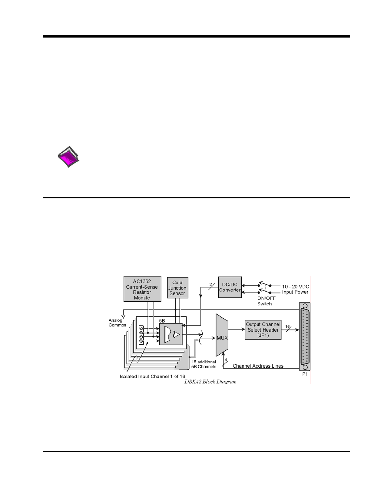
The DBK42 allows LogBook or Daq device systems to work with up to 16 5B signal conditioning
modules. Modules are available for various signal types (e.g., low-level thermocouple signals, strain-gage
signals, etc). The DBK42 offers 500 V isolation from the system and between channels. The DBK42 is
compatible with all 5B output modules, and the configuration is very flexible. You can select the type of
signal attached to each channel.
system, as needed.
o In regard to calculating system power requirements, refer to DBK Basics located near
the front of this manual.
An accessory cable connects the DBK42’s output to the P1 analog input connector. One LogBook or Daq
device can support up to 16 DBK42 units with a maximum of 256 isolated analog input channels. The
LogBook or Daq device scans the DBK42 channels at the same 10 µs/channel rate as other DBKs (256
scans in 2.56 ms in a full system).
The DBK42 can obtain power from an included AC adapter, an optional DBK30A rechargeable battery
module, or directly from a 12 VDC source (such as a car battery). The built-in power supply can serve a
fully-configured system using bridge excitation.
For DaqBoard/2000 Series applications, DBK42 is typically powered from an included AC adapter. The
unit’s built in power supply can serve a fully-configured system using bridge excitation.
DBK Option Cards and Module 967694 DBK42, pg. 1
Page 2
Each terminal block contains 4 terminals (per channel) for access to input and excitation features of 5B
modules.
The optional CN-71 and CN-72 signal connection blocks provide a convenient way of connecting analog
signals to the DBK42.
• The CN-71 is for non-thermocouple use.
• The CN-72 (with cold junction sensors) is for thermocouple use. The CN-72 has a clear
Hardware Setup
DBK42 Connection
The DBK42 has screw-terminal connectors for easy access to the analog inputs. 2-wire and 4-wire
hookups are shown later in this section.
Note: Analog channels are isolated from each other, and no analog ground is provided.
DBK42 Configuration
Up to 16 DBK42s can connect to a LogBook or a Daq device. As a daisy-chain interface,
each module must appear unique and use a different channel.
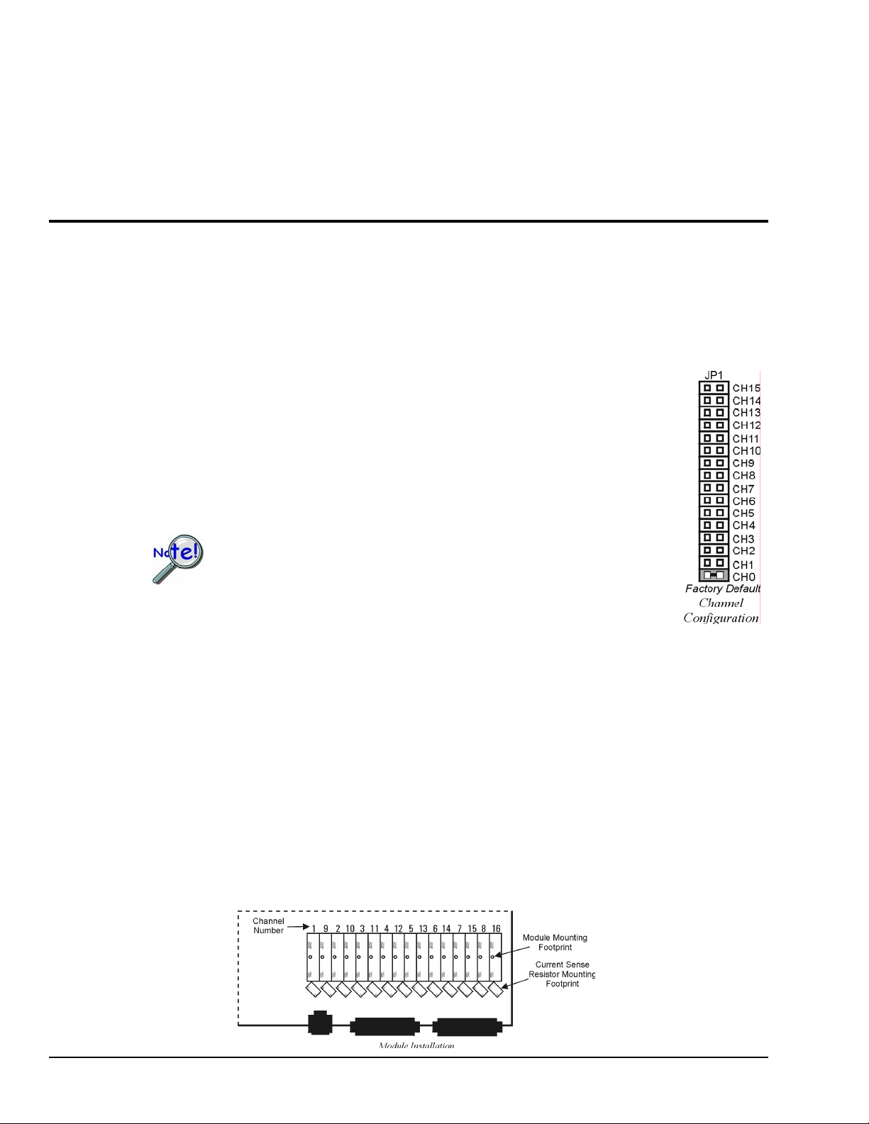
To configure the module, locate the 16×2-pin header (JP1) near the front of the DBK42
board. Note the 16 jumper locations labeled CH0 through CH15 representing the base
Analog Input Channels. Place the jumper on the channel you wish to use.
plastic shield over its screw terminals to protect you from high voltage on the input terminals.
Only one jumper is used on a single DBK42. No two cards in a system
can use the same JP1 setting.
5B Module Connection
Each input of the DBK42 is processed through a user-installed 5B signal-conditioning module. Different
5B modules are used with different transducer and signal sources. To install the modules:
1. Match the footprint of the module with the footprint on the circuit board (see figure).
2. Gently place the module into the footprint, and screw it down.
3. When installing current input modules (SC-5B32 series), install the supplied current-sense resistor
(SC-AC-1362) in the resistor footprint adjacent to the module mounting footprint.
4. Record the module’s channel number; label all units and connectors for identification.
Power Considerations
The DBK42 has an internal, isolated switching-type power supply that operates on 10-20 VDC at varying
input currents depending on the input voltage and 5B-module loading. The power drain at a given output
load is constant; input current will vary inversely with the input voltage.
DBK42, pg. 2 967694 DBK Option Cards and Modules
Page 3
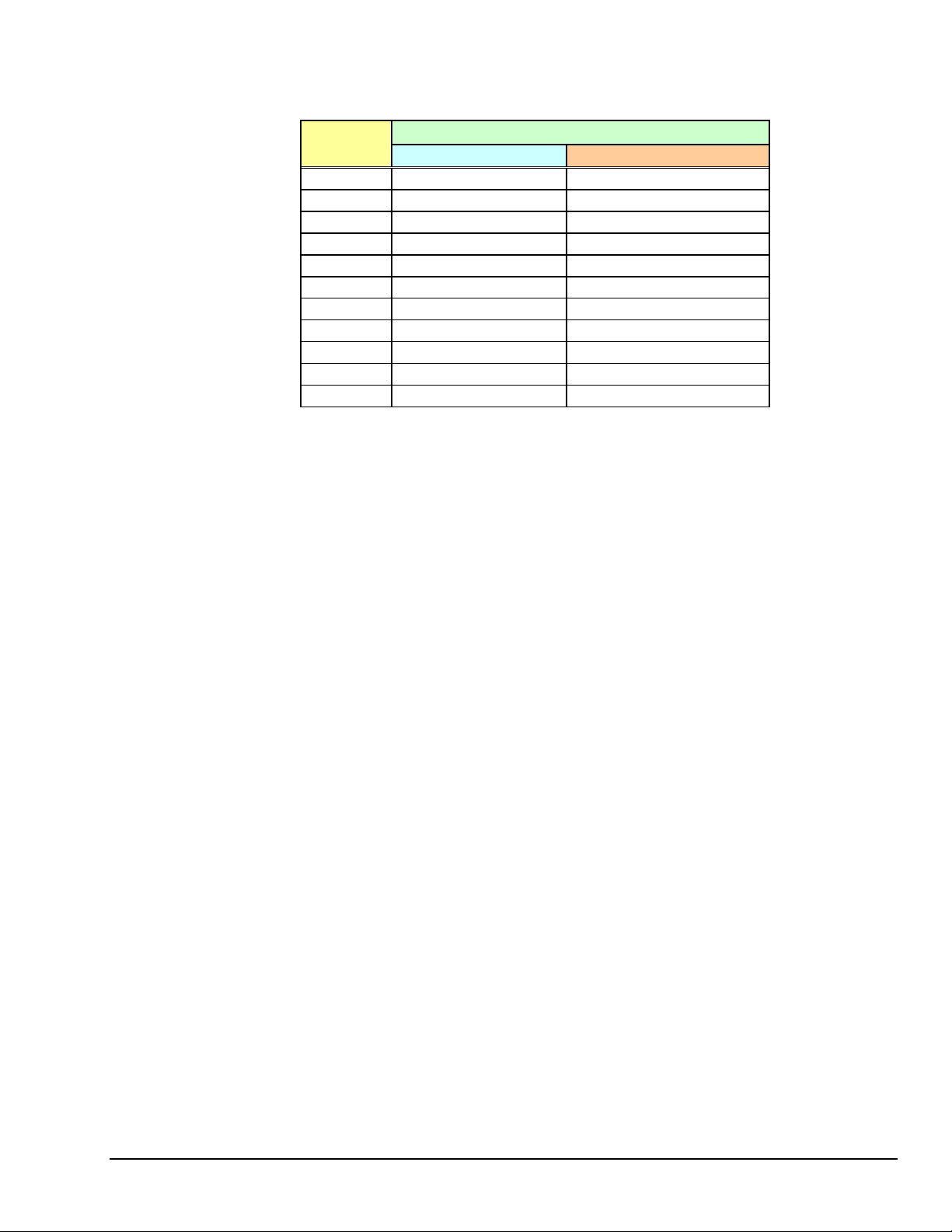
A DBK42 populated with strain-gage modules will draw more current than with other types of input
modules. The table shows the DC input requirements for the worst-case setup (with 16 strain-gage
modules or 16 thermocouple modules).
Input Volts
With Strain-Gage Modules With Thermocouple Modules
10 VDC 3.0 A 0.60 A
11 VDC 2.7 A 0.54 A
12 VDC 2.4 A 0.48 A
13 VDC 2.2 A 0.44 A
14 VDC 2.0 A 0.40 A
15 VDC 1.9 A 0.38 A
16 VDC 1.8 A 0.36 A
17 VDC 1.7 A 0.34 A
18 VDC 1.6 A 0.32 A
19 VDC 1.5 A 0.30 A
20 VDC 1.4 A 0.28 A
Input Amperes
Power sources include:
• The standard TR-25 AC plug-in power pack (provided with the DBK42) can supply 900 mA at
15 VDC. The optional TR-40U can supply 2700 mA at 15 VDC.
• The DBK30A battery pack can supply power for a typical DBK42 configuration; however, in a
fully-populated strain-gage configuration, the battery run-time will be limited to about 1½ hours.
• A 12 V lead-acid gel-cell type battery can easily power a fully-populated strain-gage
configuration. The battery drain will be about 2.4 A-hr; battery size should be considered for
systems with long run-times. (For example, a common-size 5.0 A-hr battery will operate for
about 2 hours). A typical automotive 12-V lead-acid battery (e.g., 60 A-hr) can easily power a
DBK42 for long run-times (about 24 hours).
The input fuse is a 4-A Slo-Blo 1-1/4" × 1/4" glass-type such as Littelfuse 313004 or Bussman MDL-4.
Terminal Block Connection
Input signals (and excitation leads) must be wired to the DBK42 signal termination panel. Sixteen
4-terminal blocks accept up to 16 inputs. These connectors are located on a removable PC board that plugs
into two DIN96 rectangular connectors on the rear panel.
Terminal blocks are connected internally to their corresponding signal conditioning module. The terminal
blocks accept up to 14-gage wire into quick-connect screw terminals. Terminals on each block are
numbered 1 through 4. Each type of input signal or transducer (such as a thermocouple or strain gage)
should be wired to its terminal block as shown in the figure. Wiring is shown for RTDs, thermocouples,
20 mA circuits, mV/V connections, and for full- and half-bridge strain gages.
DBK Option Cards and Module 967694 DBK42, pg. 3
Page 4

Shock Hazard! The DBK42 is designed to sense signals that may carry dangerous
voltages. De-energize circuits connected to the DBK42 before changing the wiring or
configuration.
WARNING
P1 Connection. The DBK42 attaches to the P1 analog I/O connector or to a DBK200 series P4-Adapter
P1 analog I/O connector. (Up to 16 units can be attached to one LogBook or Daq device.) Connect the
appropriate ribbon cable (with -x indicating the number of cards to be connected) from the LogBook,
Daq device, or adapter P1 port to the DB37 connector at the end of the option card.
Note: A series of interface cables are available for connecting up to sixteen DBK42s.
DBK42, pg. 4 967694 DBK Option Cards and Modules
Page 5

DaqBoard/2000 Series and cPCI DaqBoard/2000c Series Connections
DBK42 can be connected to the P1 connector of DaqBoard/2000 Series P4-adapters. Up to 16 units can be
attached to one DaqBoard/2000 Series board.
Connect the appropriate ribbon cable (with -x indicating the number of cards to be connected) from the
adapter’s P1 port to the DB37 connector at the end of the option card.
Note: A series of interface cables is available for connecting up to 16 DBK42s.
DaqBook/100 Series & /200 Series and ISA-Type DaqBoard Configuration
The DBK42 requires two setup steps in DaqBook/100 Series & /200 Series devices and DaqBoards
[ISA type]—jumpers JP1 and JP4.
1. If not using auxiliary power, place the JP1 jumper in the expanded analog mode.
Note: This default position is necessary to power the interface circuitry of the DBK42 via the internal
±15 VDC power supply. If using auxiliary power (DBK32A, or DBK33), you must remove
both JP1 jumpers. Refer to Power Requirements in the DBK Basics section of the manual.
Also, refer to the DBK32A and DBK33 sections as applicable.
2. For DaqBook/100, /112, and /120 only, place the JP4 jumper in the DaqBook/100 & /200
or ISA-type DaqBoard in single-ended mode. Analog expansion cards convert all input signals to
single-ended voltages referenced to analog common.
DaqBook/2000 Series and DaqBoard/2000 Series Configuration
No Jumper configurations are required for these /2000 series devices.
DBK Option Cards and Module 967694 DBK42, pg. 5
Page 6

Software Setup
You will need to set several parameters so DaqView can best meet your application requirements.
After the 5B module type is identified, DaqView figures out the m and b (of the mx+b equation) for proper
engineering units scaling. An example of the mx + b equation follows shortly.
The mx + b calculations for most 5B modules are included within LogView software.
PDF Note:
Reference Note:
o For DaqView information refer to chapter 3, DBK Setup in DaqView and to the DaqView
PDF included on your data acquisition CD.
o For LogView information refer to chapter 4, DBK Setup in LogView and to the LogView
section of the LogBook PDF included on your data acquisition CD.
o The API includes functions applicable to the DBK42. Refer to related material in the
Programmer’s Manual (p/n 1008-0901) as needed.
®
During software installation, Adobe
PDF versions of user manuals automatically install onto
your hard drive as a part of product support. The default location is in the Programs group,
which can be accessed from the Windows Desktop. Refer to the PDF documentation for
details regarding both hardware and software. Note that you can also access PDF documents
directly from the data acquisition CD via the <View PDFs> button on the CD’s opening
screen.
mX +b, an Example
The Customize Engineering Units dialog box can be
accessed via the DaqView Configuration main
window by activating the Units cell [for the desired
channel], then clicking to select mX+b.
From the Customize Engineering Units dialog box
(see figure at right), you can enter values for m and b
components of the equation that will be applied to
the data. There is also an entry field that allows you
to enter a label for the new units that may result from
the mX+b calculation.
An example of mX + b equation use follows.
DBK42, pg. 6 967694 DBK Option Cards and Modules
Page 7

Engineering Units Conversion Using mx + b
Most of our data acquisition products allow the user to convert a raw signal input (for example, one that is
in volts) to a value that is in engineering units (for example, pressure in psi). The products accomplish this
by allowing the user to enter scale and offset numbers for each input channel, using the software associated
with the product. Then the software uses these numbers to convert the raw signals into engineering units
using the following “mx + b” equation:
(1) Engineering Units = m(Raw Signal) + b
The user must, however, determine the proper values of scale (m) and offset (b) for the application in
question. To do the calculation, the user needs to identify two known values: (1) the raw signal values, and
(2) the engineering units that correspond to the raw signal values. After this, the scale and offset
parameters can be calculated by solving two equations for the two unknowns. This method is made clear
by the following example.
Example
An engineer has a pressure transducer that produces a voltage output of 10.5 volts when the measured
pressure is 3200 psi. The same transducer produces an output of 0.5 volt when the pressure is 0 psi.
Knowing these facts, m and b are calculated as follows.
A - Write a pair of equations, representing the two known points:
(2) 3200 = m(10.5) + b
(3) 0 = m(0.5) + b
B - Solve for m by first subtracting each element in equation (3) from equation (2):
(4) 3200 - 0 = m(10.5 – 0.5) + (b - b)
(5)
Simplifying gives you: 3200 = m(10)
(6)
This means: m = 320
C - Substitute the value for m into equation (3) to determine the value for b:
(7) 0 = 320 (0.5) + b
(8)
Therefore: b = - 160
Now it is possible to rewrite the general equation (1) using the specific values for m and b that we just
determined:
(9) Engineering Units = 320(Raw Signal) - 160
The user can then enter the values of m and b into the appr opriate location using the facilities provided by
compatible data acquisition software, for example: WaveView, DaqView, Personal DaqView, LogView, and
TempView. The software uses equation (9) to calculate signal values in engineering units from that point
on.
DBK Option Cards and Module 967694 DBK42, pg. 7
Page 8

DBK42 – Specifications
Name/Function: 16-Slot 5B Signal Conditioning Module
Module Capacity: 16 (input only) 5B modules
Size: 8.5" × 11" × 3.5" (11" × 11" × 3.5" with optional CN-71 or CN-72)
Weight: 4 lb (with no modules installed)
Cable (optional): CA-37-1
Power Requirements: 10-24 VDC @ 2.6 - 0.3 A
With 16 thermocouple-type modules:
12 VDC @ 0.50 A
15 VDC @ 0.40 A
18 VDC @ 0.35 A
With 16 strain-gage type modules:
12 VDC @ 1.9 A
15 VDC @ 1.5 A
18 VDC @ 1.3 A
DC Input Fuse: 3A
Power Indicator: LED powered by internal 5 VDC
Power Connection: DIN5 ×2 for daisy-chaining
AC Power Pack::
120 VAC to 15 VDC converter
120 VAC to 15 VDC @ 2.0 A (optional)
Input Connections: DIN96 rectangular, standard, screw terminal adapter (optional)
Connection: Male DB37 mates via CA-37-1 cable with P1
DC/DC Converter: 10-24 VDC to 5 VDC (isolated)
Isolation:
Input Power to System: 500 VDC
Signal Inputs to System: 1500 VDC
Input Channel-to-Channel: 500 VDC
DBK42, pg. 8 967694 DBK Option Cards and Modules
 Loading...