

Page 1
DBK41 10-Slot Expansion Module
Overview …… 1
Hardware Setup …… 2
Card Configuration …… 2
Power Configuration …… 2
Card Insertion …… 3
EMI Shield Plates for CE Compliance …… 4
System Connection …… 5
DBK41 – Specifications …… 5
Overview
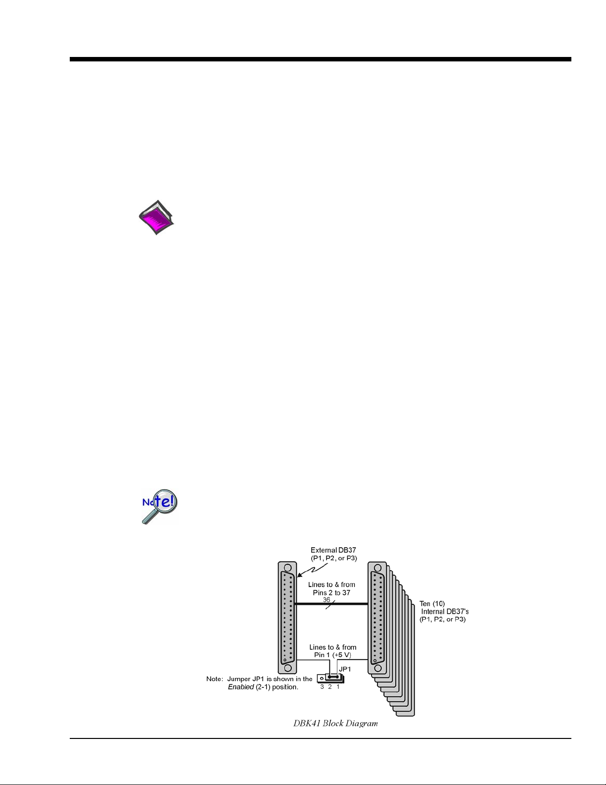
The DBK41 is a metal enclosure that holds up to 10 DBK cards. The exterior front panel has a male DB37
connector that leads to the LogBook or Daq device or further expansion via a CA-37-x cable. On the
inside of the front panel, a backplane printed circuit board (PCB) uses 10 female DB37s with their pins
connected in parallel to distribute the P1 interface (can also be used with P2 or P3). From the rear panel,
the DBKs’ signal input lines exit to their respective transducers.
Reference Notes:
o Chapter 2 includes pinouts for P1, P2, P3, and P4. Refer to pinouts applicable to your
system, as needed.
o In regard to calculating system power requirements, refer to DBK Basics located near
the front of this manual.
An optional EMI kit provides shield plates for the rear panel to make the DBK41 CE-compliant and
prevent EMI from DBKs entering the test environment (or vice-versa). The EMI kit also functions as an
electrical safety barrier.
Some DBK cards require a lot of power, in relation to other cards, and the use of power is an important
concern. DBK cards can obtain power externally from a LogBook, DaqBook, DaqBoard; or internally
from a DBK32A or DBK33 card. Refer to Power Requirements in the DBK Basics section, as well as the
sections for the DBK32A and/or DBK33, as applicable.
A power card in any slot (other than the slot leftmost from rear view) will power the
other cards via the backplane. A front panel LED will light whenever power from any
source is on the backplane. DBK41’s JP1 jumper can be positioned to disable the +5 V
power line from the external DB37. This prevents a DBK33 power supply from
interfering with other devices.
DBK Option Cards and Modules 877095 DBK41, pg. 1
Page 2
Hardware Setup
Setup concerns include card and power configuration, proper card insertion, the use of EMI shields for CE
compliance, and mounting [or stacking] of hardware components.
In regard to mounting: metal splice plates can be used to rigidly mount a LogBook or DaqBook on top of a
DBK41 or other device that shares the same footprint. For applications in which temporary mounting is
convenient: a LogBook, DaqBook or notebook PC can be temporarily mounted to a DBK41 with the use
of industrial-strength dual-lock pads or strips.
Card Configuration
Each DBK card should be checked for proper configuration, and re-configured if needed, before being
inserted into the DBK41. Refer to the individual DBK Document Modules that are applicable to your
system.
Power Configuration
Power must be configured to prevent multiple power supplies from interfering with each other via the P1
interface. DBK41, LogBook/360, DaqBook/100 Series & /200 Series, and ISA-type DaqBoard each have
JP1 jumpers that must be properly configured in regard to power. Details for each follow.
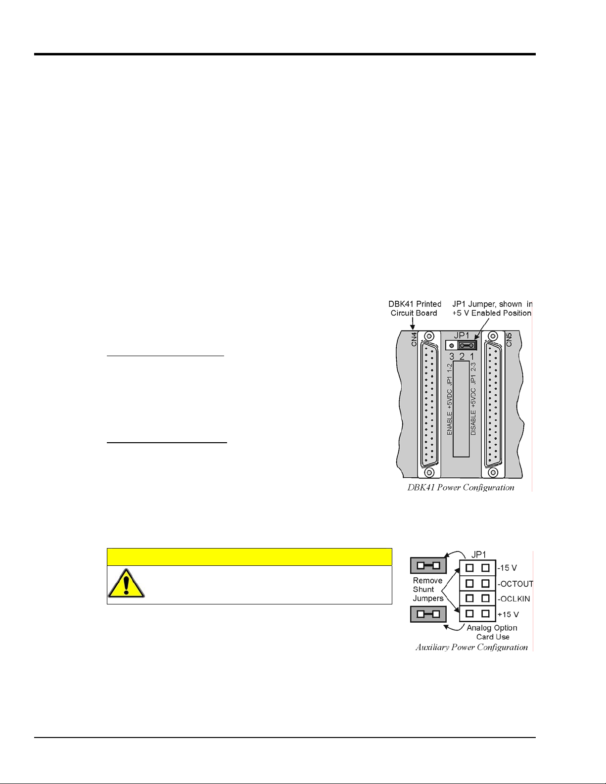
JP1 in the DBK41
On the DBK41 backplane, JP1 is a 3-pin jumper positioned between
DB37 connectors for card number 4 (CN4) and card number 5
(CN5). Two settings are possible, as follows:
ENABLE +5 VDC JP1 1-2
When JP1 pins 1 and 2 are jumpered, the +5 VDC line to the
external P1 connector is enabled. The 5 V (VCC) is externally
supplied to pin 1 for cards 1 through 10 (CN1 through CN10). The
+5 VDC power can come from a LogBook, DaqBook, or DaqBoard
through a CA-37-x cable on pin 1 of P1. If not using a DBK33, JP1
should be enabled.
DISABLE +5 VDC JP1 2-3
When JP1 pins 2 and 3 are jumpered, the +5 VDC line to the
external P1 connector is disabled. When using a DBK33 power
card in the DBK41, the JP1 jumper must be set on pin 2 and 3. The
JP1 2-3 setting prevents the DBK33’s +5 V from interfering with
external devices via the P1 interface.
JP1 in the DaqBook/100 Series & /200 Series and DaqBoard [ISA type]
CAUTION
DBK power cards must not be connected until JP1
jumpers have been removed. Otherwise, equipment
damage could result.
If a DBK32A or DBK33 is used, you must remove the shunt jumpers
from the JP1 header located inside the DaqBook/100 Series & /200 Series
device or DaqBoard [ISA type]. DaqBook/100 Series & /200 Series
devices and DaqBoards [ISA type] are shipped with these shunts
positioned to deliver ±15 V analog power to P1.
Note: The jumpers can be placed on the -OCTOUT and -OCLKIN pins but should be removed if there is
interference with card operation (counter-timer).
DBK41, pg. 2 877095 DBK Option Cards and Modules
Page 3

JP1 and JP2 in LogBook/360
Proper jumper configuration limits LogBook/360’s P1 bus to one power source. There should never be
more than one power source. The jumpers are located inside the chassis, on the unit’s P1 Interconnect
Board.
JP1. Only remove LogBook/360’s JP1 jumper if a DBK33 is used with the system.
JP2. Only remove the LogBook/360’s JP2 jumper if DBK cards are to be powered from LogBook/360’s
DaqBook/2000 Series & DaqBoard/2000 Series Configuration
No jumper configurations are required for these /2000 series devices.
Card Insertion
Each DBK card has a DB37 male connector which mates with the DB37 female connectors inside the
DBK41 chassis. To insert DBK cards into the DBK41 chassis, refer to the figure and perform the
following steps.
Note: Cards using screw-connectors for signal input lines must be wired before insertion.
1. Disconnect power from all units to be connected.
internal PCB.
Reference Note:
Refer to the LogBook User’s Manual, 461-0901 for information regarding LogBook systems.
2. Place the DBK41 on a flat surface; loosen the two thumbscrews on rear of the case; and remove the
top cover by sliding it off.
3. Align the DBK card with the DBK41 connector to be used (CN1 to CN10). The first slot must always
be occupied; however, a DBK32A or DBK33 power card may not occupy the first slot. Any of the
remaining 9 slots can be used or unused.
4. To clear the lip on the rear panel, tilt the rear of the card upward. Engage the P1 connectors of the
card and chassis, and press together gently to avoid damage to the pins.
5. Press down the rear of the card, aligning it within the metal dimples at the rear of the DBK41.
6. After cards are in place, reassemble the DBK41’s top cover and attach optional shield plates
(described next); then re-connect and power up the system.
DBK Option Cards and Modules 877095 DBK41, pg. 3
Page 4

EMI Shield Plates for CE Compliance
To reduce electro-magnetic interference (EMI) escaping from (or entering into) the enclosure, a CE kit
provides shield plates that attach to the rear of the DBK41. The kit also functions as an electrical safety
barrier. With shield plates attached (a combination of 3 types supplied), the system meets CE standards.
The kit includes:
• Full shield plates to cover empty (unused) slots
• Partial shield plates to surround DBKs in a slot (except a power card)
• Partial shield plates to surround a DBK32A or DBK33 power card
• Screws and star washers to secure the shields to the chassis
Note: The CE kit is included with the DBK41/CE and an optional accessory for a DBK41.
The shields have a support tab that slides over the edge of the bottom plate and a screw hole for
attachment to the top plate. When tightened, the screws cause the washers to pierce the surface
coating into the metal to make a good contact with chassis ground.
Reference Note:
The Signal Management chapter contains additional information pertaining to CE Compliance.
DBK41, pg. 4 877095 DBK Option Cards and Modules
Page 5

System Connection
A short ribbon cable (CA-37-x) attaches the DBK41 to the main unit. Connecting the DBK41 to any port
other than P1 may damage devices in the system. Likewise, only analog expansion cards may be installed
in the DBK41.
Note: For CE compliance, the CA-37-x cable must be replaced with a CA-143-7 or
CA-143-18. Multiple chassis require a “T” connector (part # CN-143) for branching.
Examples of DBK41 Connections [with DBK32A] and Cascading Power
DBK41 - Specifications
Name/Function: 10-Slot Analog Expansion Module
Card Capacity: 10 slots to hold standard DBK option cards
Weight: 4 lb (with no cards installed)
Cable (optional): 8" ribbon with DB37 female to DB37 female (CA-37-x)
Power Indicator: LED powered by external device’s 5 VDC
Connection: Male DB37, mates via CA-37-x cable with P1
DBK Option Cards and Modules 877095 DBK41, pg. 5
Page 6

DBK41, pg. 6 877095 DBK Option Cards and Modules
 Loading...