

Page 1
DBK40 18- Connector BNC Analog Interface
Overview …… 1
Hardware Setup …… 2
Using the DBK40 …… 2
DBK40 – Specifications …… 3
Overview
The DBK40 is a termination panel consisting of 18 BNC connectors. The unit provides an easy means of
attaching analog signals from BNC cables to a to a DB-37 connector, such as P1 on a LogBook, a Daq
device, or a DBK module.
The panel includes:
Reference Notes:
o Chapter 2 includes pinouts for P1, P2, P3, and P4. Refer to pinouts applicable to your
system, as needed.
o In regard to calculating system power requirements, refer to DBK Basics located near
the front of this manual.
• 16 analog input channels
• 2 analog output channels (DAC-0 and DAC-1)
• a slide switch (DAC1/TTL-TRIG Switch)
• a male DB37 connector
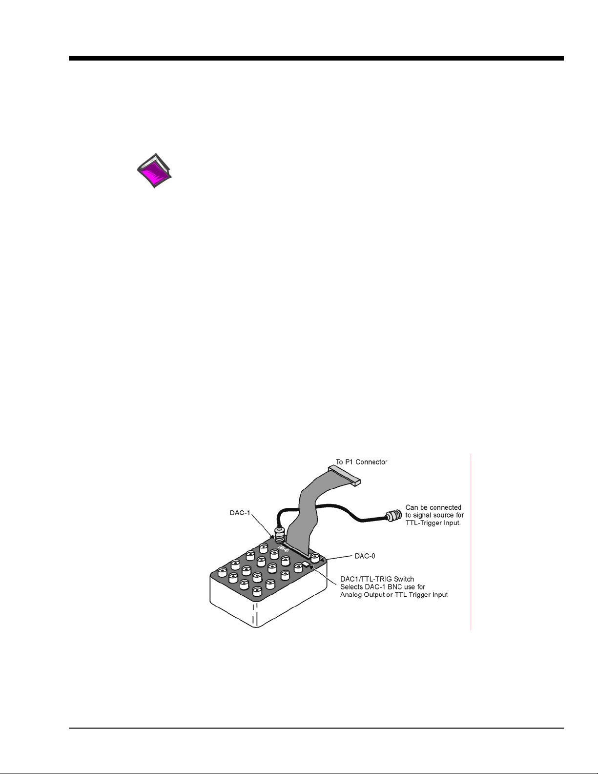
The DAC1/TTL-TRIG Switch is used to select the mode of the DAC-1 BNC connector. DAC-1 can be
used as an analog output channel, or as a TTL Trigger Input.
DBK40
DBK Option Cards and Modules 879795 DBK40, pg. 1
Page 2
Hardware Setup
The DBK40 has a male DB37 connector that is pin-compatible with the P1 port. Typically a 6-foot ribbon
cable is provided to attach the DBK40 to the P1 connector of the primary acquisition device, e.g., a
LogBook or DaqBook.
Connect one end of the ribbon cable to the DB37 connector of the DBK40 and the cable's other end to the
Analog I/O Port (P1) of the primary data acquisition device.
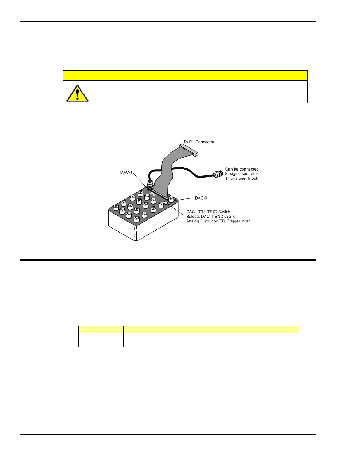
Connecting the DBK40 to a port other than P1 may result in damage to the system.
CAUTION
Using the DBK40
The DBK40 is equipped with BNC connectors for 16 single-ended or 8 differential inputs. Also provided
are BNC terminals for DAC0 and DAC1 analog outputs.
The DAC-1 connector may be used for access to the LogBook or Daq Device Analog I/O TTL trigger
input. The position of the DBK40 slide switch determines the use of DAC-1, as indicated in the following
table. Verify that this switch is in the correct position for your application.
Switch Setting Description
TTL/TRIG Allows the connector to be used for TTL trigger input.
DAC-1 Allows the connector to be used DAC-1 output.
The collars of all of the BNC connectors are common to each other and analog ground. When the TTL
trigger input is selected (via the slide switch), the isolated ground plane of the TTL-TRG/DAC1 connector
is referenced to digital or TTL ground. Most of the top area of the DBK40’s PC board is ground plane that
provides excellent low-impedance, low-noise signal interfacing.
DBK40, pg. 2 879795 DBK Option Cards and Modules
Page 3

Connect your analog signals to the unit as you would to any other BNC connector. The outer shell is
ground; the center pin is the signal.
The figure below shows connections for single-ended and differential inputs. In the differential mode,
channels 0 to 7 are high; 8 to 15 are low (0 & 8, 1 & 9, 2 &10, etc).
DBK40 - Specifications
Name/Function: BNC Analog Interface Module
Connection: Male DB37 mates with P1.
Analog Input Connection: One BNC connector for each of 16 analog input channels.
Single-Ended Mode: Center conductor carries signal, outer conductor carries signal ground.
Differential Mode: Center conductor of two adjacent BNC connectors carries high and low input signals; the
outer conductors of both are attached to system ground.
Analog Output Connection: One BNC connector for each of 2 analog output channels;
center conductor carries signal, outer conductor carries signal ground.
TTL Trigger Input Connection: One analog output BNC connector can be switched to provide a TTL trigger
input connection; in TTL mode, the second analog output channel is unavailable on the BNC
connector.
Size: 6.8" wide × 5.3" long × 2.3" high
Weight: 21 oz
Length of Supplied Cable: 6 ft
DBK Option Cards and Modules 879795 DBK40, pg. 3
Page 4

DBK40, pg. 4 879795 DBK Option Cards and Modules
 Loading...