

Page 1
DBK34A UPS / Battery Module
Hardware Setup for 12 Volt (Default) or 24 Volt Operation …… 3
Indicators …… 4
Runtime …… 4
Charging …… 4
Fuse Replacement …… 5
Environmental Concerns …… 6
DBK34A – Specifications …… 6
DBK34A is similar to DBK34 in appearance and operation; but there are differences.
Before proceeding with this document module, verify that your device is a DBK34A. If
your device does not have the “A” suffix, use the DBK34 Document Module instead of this
one.
Reference Notes:
o Chapter 2 includes pinouts for P1, P2, P3, and P4. Refer to pinouts applicable to your
system, as needed.
o In regard to calculating system power requirements, refer to DBK Basics located near
the front of this manual.
Overview
The DBK34A can power a data acquisition system in portable or in-vehicle UPS applications (both 12 V
and 24 V systems). Power storage capacity is 5 A-hr @ 12 VDC or 2.5 A-hr @ 24 VDC.
For reliable data acquisition in a vehicle, the DBK34A provides clean and consistent operating power:
• Prior to engine/generator start
• During engine start-up (battery sag due to the high-current demand of starter motor and
solenoid)
• After engine turn off.
• Before and after connection to the vehicle
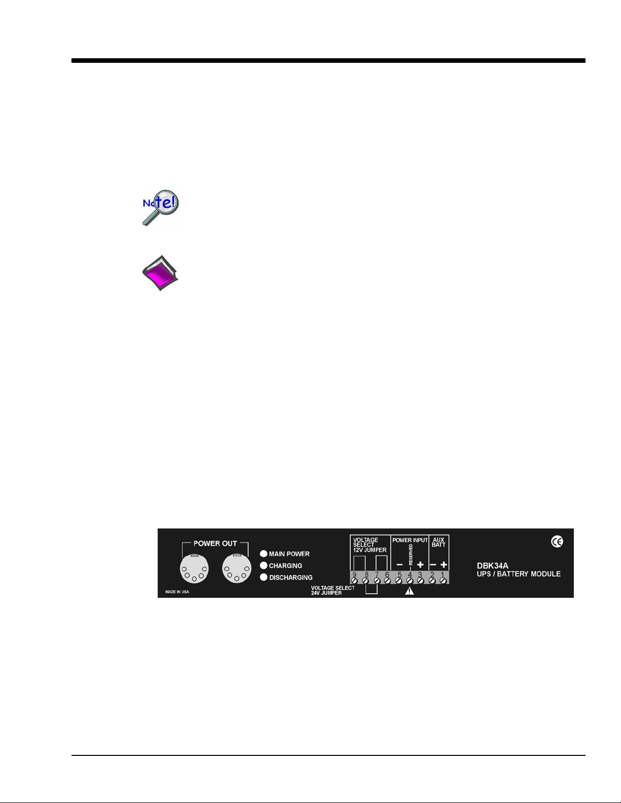
DBK34A Front Panel
The DBK34A contains two sealed-lead rechargeable batteries (Gel-Packs), associated charging circuits and
current indicators. Typically, these batteries can last more than 500 full cycles and up to 10 years standby
lifetime at room temperature. Recharging is fast, and extreme temperature performance is good. The
DBK34A can be used with the LogBook, DaqBook, WaveBook, and related DBKs and WBKs. The unit’s
rugged metal package has a compatible 8×11” footprint for convenient stacking with Velcro tabs and
optional splice plates and handles for carrying.
DBK Option Cards and Modules 879795 DBK34A, pg. 1
Page 2
Main and auxiliary power input comes from 12 or 24 VDC via a terminal block on the unit’s front panel
(12 or 24 V modes are set by front-panel jumpers). Automatic, temperature-compensated charging circuits
recharge the internal batteries quickly and safely. For trouble-free operation, you must fully charge the
batteries before use. The charged battery runtime will depend on the load and mode of o peration.
During use of the internal batteries, the Charging LED blinks and a beeper sounds when battery life is
almost exhausted. Within a few minutes, internal cutoff circuits disconnect the load from the batteries to
prevent the possibility of deep-cycle damage.
Note: Current protection is provided by four fuses: Two 7.5A fuses for the unit’s internal batteries,
one 7.5 A fuse for an auxiliary (external) battery, and a 15 A fuse for the power input.
You can use a CA-172 cable to connect a vehicle battery (via a cigarette lighter) to the DBK34A
terminal board. The cable is six feet long, contains a cigarette lighter adapter at one end, and
stripped leads (for terminal connection) at the other.
For trouble-free operation, fully charge the batteries before use.
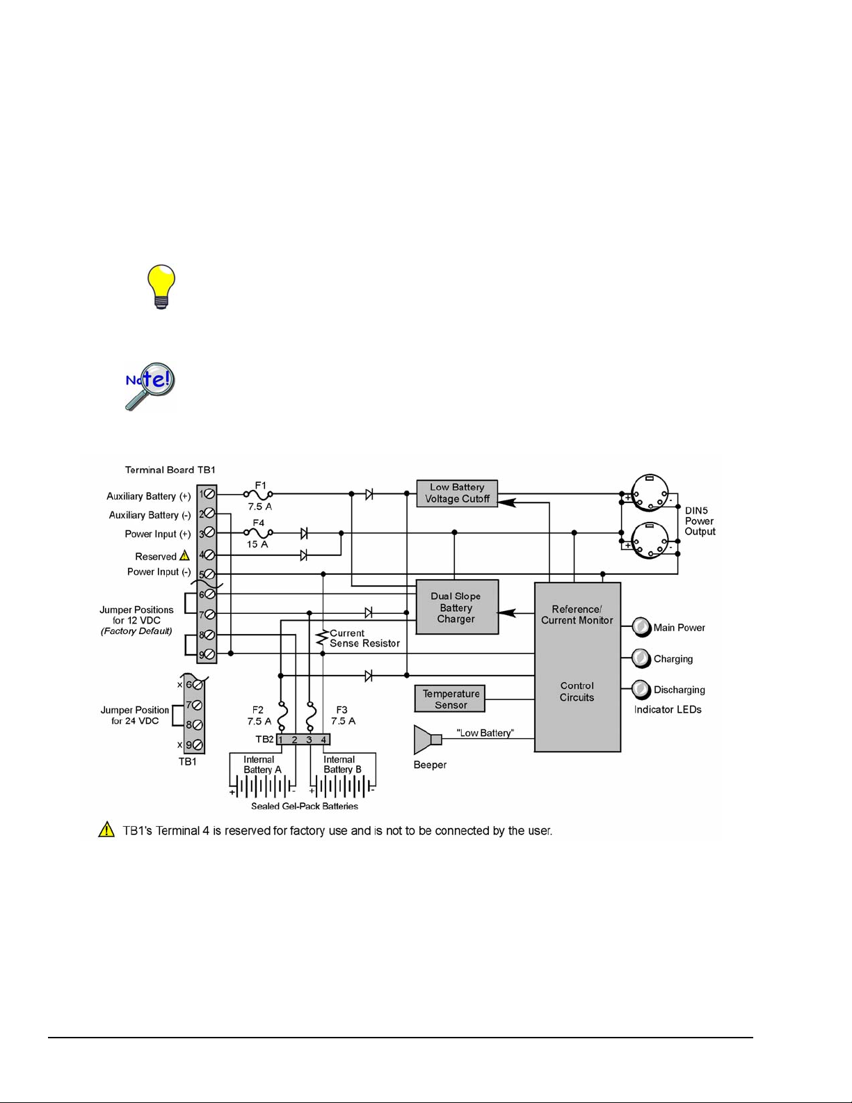
DBK34A Block Diagram
DBK34A, pg. 2 879795 DBK Option Cards and Modules
Page 3

Hardware Setup for 12 Volt (Default) or 24 Volt Operation
The DBK34A is configured for 12 volt or 24 volt operation via placement of jumpers on the front panel’s
screw-terminal block (TB1). DBK34A’s screw-terminal numbers read as follows, when read from left to
right: 9, 8, 7, 6, 5, 4, 3, 2, 1.
DBK34A’s Screw Terminal Board, TB1
For 12 Volt Operation:
1. Remove jumper from terminals 8 and 7, if present.
2. Use a jumper to short terminals 9 and 8.
3. Use a jumper to short terminals 7 and 6.
For 24 Volt Operation:
1. Remove jumpers from terminals 9 and 8, if present.
2. Remove jumpers from terminals 7 and 6, if present.
3. Use a jumper to short terminals 8 and 7.
Power In (12 or 24 VDC only).
1. Connect the MAIN POWER INPUT (+) positive to Terminal 3 of TB1.
2. Connect MAIN POW ER INPUT (-) negative to Terminal 5 of TB1.
TB1’s Terminal 4 is reserved for factory use and is not to be connected by the user.
The use of an optional auxiliary battery will extend run -time.
Auxiliary Batteries.
Auxiliary batteries for use with DBK34A, must be: (a) of lead-acid chemistry, (b) in the
2 to 3 A-Hr range, and (c) of the same voltage as that set by the Voltage Select Jumpers. Auxiliary
batteries charge and discharge in the same manner as the internal batteries.
If an auxiliary battery is to be used:
1. Connect AUX BATT (+) positive to Terminal 1 (of TB1).
2. Connect AUX BATT (-) negative to Terminal 2 (of TB1).
Power Out.
The pinout at the right applies to the two POWER
OUT DIN5 connectors.
DIN5 Power Output Connector (2 per DBK34A)
DBK Option Cards and Modules 879795 DBK34A, pg. 3
Page 4

Indicators
Runtime
Three front-panel LED indicators provide power and charging status information.
LED Indicators & Descriptions
MAIN POWER
CHARGING
DISCHARGING
Lights when the DBK34A power input is connected to a source of at least 12.25 VDC
Lights when the internal batteries are being fast-charged at a rate of 0.1 amp/cell or greater.
Lights when internal batteries (or auxiliary batteries) are discharging at a rate of 0.25A or greater.
For trouble-free operation, you must fully charge the batteries before use.
Charged battery runtime depends on the load and on the mode of operation.
Approximate runtime under various loads can be computed from the storage capacity (5 A-hr in 12 V
mode; 2.5 A-hr in 24 V mode) and the load (main unit and other DBKs). See Power Requirements in the
DBK Basics section.
The following Load Wattage vs. Hours graph is for a typical new battery that is fully charged.
Charging
In general, lead-acid batteries [and related Gel-Packs] require charging at 120% of drain energy (e.g.,
the 5 A-hr DBK34A requires a charge equal to or greater than 6 A-hr). Charging times vary; but
4 to 5 hours at 14 V is typical for a completely discharged battery; after which, charging may continue
indefinitely.
Note that 16 to 18 VDC at the power input is required for optimal charging.
Voltage applied to a DBK34A must not exceed 30 VDC.
DBK34A, pg. 4 879795 DBK Option Cards and Modules
CAUTION
Page 5

Fuse Replacement
DBK34A contains four MINI ATO fuses that can be replaced by the user. Note that you should always
check your unit for blown fuses prior to sending it back to the factory for repair. This could save you time
and money.
The following table indicates the probable reason that a particular fuse may have blown, and includes part
numbers and fuse rating.
Fuse Rating Probable Cause of Blowing Fuse Replacement Fuse
F1 7.5 A Auxiliary Battery overload. 7.5A MINI ATO, LITTLEFUSE# 297-07.5
F2 7.5 A Output overload. 7.5A MINI ATO, LITTLEFUSE# 297-07.5
F3 7.5 A Output overload. 7.5A MINI ATO, LITTLEFUSE# 297-07.5
F4 15 A Input overload. 15A MINI ATO, LITTLEFUSE# 297-015
To replace a fuse:
1. Disconnect the DBK34A from loads and from supply power.
2. Remove the DBK34A’s cover plate. This requires the removal of 4
screws (2 per side).
3. Examine the fuses (F1 through F4) to see which, if any, have blown.
Note that you can usually see the blown element through the fuse’s
transparent casing.
4. Replace the blown fuse with the appropriate replacement fuse (see
preceding table). Note that the fuse value is present on top of the fuse;
also, the fuses are color coded as an aid to identification.
5. Replace the DBK34A cover and secure with screws (removed in step 2).
DBK34A, Fuse Location Reference
DBK Option Cards and Modules 879795 DBK34A, pg. 5
Page 6

Environmental Concerns
DBK34A Gel-Pack batteries contain toxic materials (Pb and H2SO4). At the end of
the battery life cycle the Gel-Packs must be recycled or properly disposed of.
DBK34A – Specifications
Name/Function: UPS / Battery Module
Battery Type: sealed-lead gel-pack
Number of Battery Packs: 2
Battery Pack Configuration: 6 series-connected D cells
Output Voltage: 12 V or 24 V (set by jumpers on TB1)
Output Fuses: F2 and F3; one 7.5 A fuse for each internal gel-pack battery
Input Fuses: F1: 7.5 A for auxiliary battery, F4: 15 A for input overload
Battery Capacity (Amp-Hours):
5 A-hr in 12 V mode (parallel)
2.5 A-hr in 24 V mode (series)
Operating Temperature: -20°F to 122°F (-29°C to 50°C)
Size: 8½ × 11 × 1¾ in. ( 216 × 279 × 44 mm)
Weight: 7.2 lb (3.27 kg)
CAUTION
DBK34A, pg. 6 879795 DBK Option Cards and Modules
 Loading...