

Page 1
DBK32A Auxiliary Power Supply Card
Overview …… 1
Configuring the Primary Device for use with a DBK32A …… 2
Connecting the DBK32A …… 3
Specifications …… 4
Reference Notes:
o Chapter 2 includes pinouts for P1, P2, P3, and P4. Refer to pinouts applicable to
Overview
your
system, as needed.
o In regard to calculating system power requirements, refer to DBK Basics located near
the front of this manual.
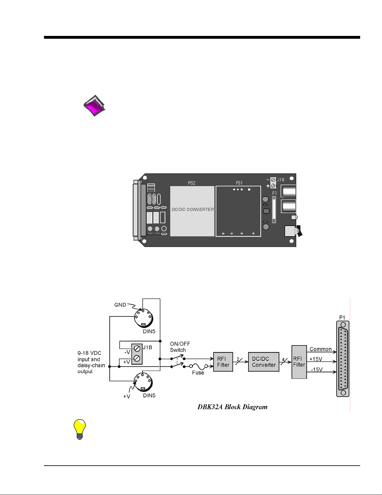
DBK32A Power Supply Card
The DBK32A provides added power in configurations where the number of expansion cards exceeds the
power available from a LogBook, DaqBook, or DaqBoard. For power, the DBK cards rely on voltages
supplied via the P1 connection. The DBK32A supplies ±15 V @ 500 mA via the P1 bus and is compatible
with all analog DBK cards.
The DBK32A does not provide +5 V. If +5 V is required by the DBKs in use, you should use the
DBK33 Triple-Output Power Supply. Refer to the DBK33 Document Module for additional
information.
DBK Option Cards and Modules 879795 DBK32A, pg. 1
Page 2
Configuring the Primary Device for use with a DBK32A
Configuration for:
DaqBook/100 Series
DaqBook/200 Series
DaqBoard/100 Series
DaqBoard/200 Series [ISA-type boards]
CAUTION
You must configure the DaqBook/100 Series & /200 Series devices or DaqBoard
[ISA type] before connecting the DBK32A. Do not connect the P1 cable without
first removing the shunt jumpers from JP1 inside the DaqBook/100 Series & /200
Series device or DaqBoard [ISA type]. Failure to remove these jumpers can result
in damage to the DBK32A and the DaqBook/100 Series, DaqBook/200 Series or
DaqBoard [ISA type].
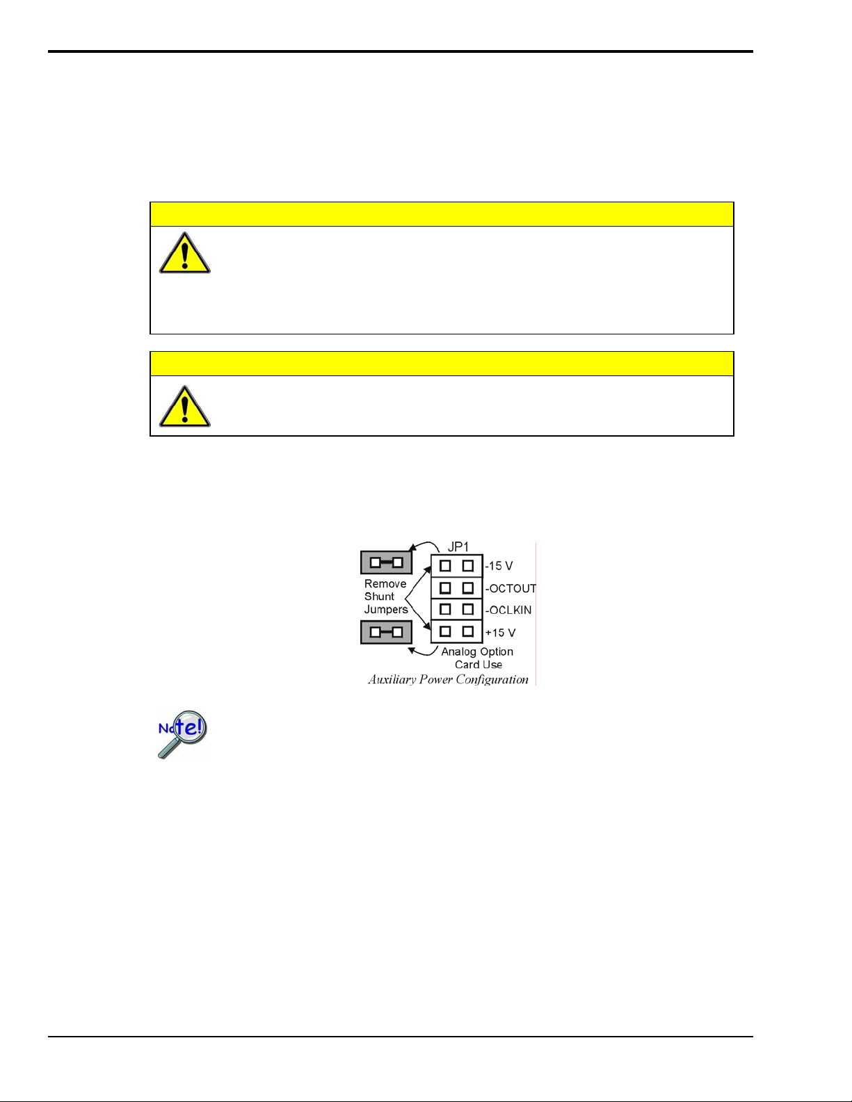
CAUTION
Using a DBK32A requires you to entirely remove the shunt jumpers from header JP1 inside the
DaqBook /100 Series & /200 Series or DaqBoard [ISA type], as shown in the figure. DaqBooks/100
Series & /200 Series and DaqBoards [ISA type] are shipped with these shunts positioned to deliver
analog power to P1.
Do not place jumpers on the -OCTOUT and -OCKLIN pins.
If configured such, damage to the 8254 timer chip will result.
JP1 default position will not work with a DBK32A. Shunt jumpers must be removed
before connecting DBK32A. See previous Cautions.
Configuration for:
DaqBook/260
DaqBook/2000 Series
No hardware configuration is performed in regard to using the
DBK32A with these devices.
DaqBoard/2000 Series
DBK60
LogBook/300
LogBook/360
Configuration for:
DBK41
When a DBK32A is installed in a DBK41, the DBK41 should have its JP1
jumper in the “ENABLE +5 VDC” position. Refer to the DBK41 section
of the manual for additional information.
DBK32A, pg. 2 879795 DBK Option Cards and Modules
Page 3

Connecting the DBK32A
The DBK32A can be installed into the internal expansion slot of a DaqBook/112, DaqBook/216,
DaqBook/2000X, a 3-Slot DBK10, a 3-slot DBK60, or a 10-Slot DBK41. It can also be used in a
LogBook/360 and DaqBook/260.
If you will be using a 3-port DaqBook, i.e., DaqBook/100, /120, /200, /260, or /2000 Series
with a DBK41, then the best location for the DBK32A is the right-hand end-slot of the
DBK41 when facing the DBK41’s rear panel. This will be the left-hand slot if facing the
DBK41 from the front-panel.
DBK32A’s P1 Connector
DBK32A’s DB37 P1 connector interfaces with the analog DBK in one of two ways:
a) Via a P1 interface backplane, such as in the case of installing the DBK32A in a DBK41.
b) Via a CA-37-x cable, which interfaces between the DBK32A’s P1 connector and the P1
connector(s) of the analog DBK(s) that it is to supply power to.
DBK32A’s DIN5 Connectors
The DBK32A can be powered from a 9 to 18 VDC source such as an AC/DC power adapter, a DBK30A
battery module, or a car battery.
The DBK32A has two DIN5 power connectors to allow for the cascading of multiple DBK32As
(via a CA-115 power cable). The lower right-hand section of the preceding figure portrays this scenario.
Note that a DBK32A can share a power source with an acquisition device. For example, you can connect
a CA-115 power cable to the DIN5 Power Out connector of a DaqBook, DaqBoard, or LogBook and then
connect the other end of the CA-115 cable to one of the DIN5 connectors on the DBK32A.
Examples of DBK32A Connections
DBK32A’s J1B Terminal Block
Terminal block J1B has one positive (+) and one negative (-) screw terminal. The terminal block power
connection is available as an alternative to a DIN5 connector. As indicated in the block diagram on page 1,
all three connectors are in parallel.
DBK Option Cards and Modules 879795 DBK32A, pg. 3
Page 4

DBK32A – Specifications
Name/Function: Auxiliary Power Supply Card
Isolation, Input to Output: 500 VDC
Output Voltages:
+15 VDC (nominal) @ 535 mA
-15 VDC (nominal) @ 535 mA
Line Regulation: 0.5% (maximum)
Load Regulation: 1.0% (maximum)
Total Output Power: 16 VA (full load)
Input Voltage Range: 9 to 18 VDC
Input Current Range:
1.05A @ 18 VDC
10A @ 9 VDC
Size: 209 mm x 19 mm x 82 mm (8-1/4 “ x 3/4" × 3-1/4")
Full Load Efficiency: 80% Typical
Input Connections: DIN-5 (×2 for daisy-chaining)
Output Connections: DB37 Male
Parallel Provision: OR-ing diodes in output lines
Controls: ON/OFF rocker arm switch
Indicators: LED driven by positive output
Over-Voltage Protection: Fuse followed by 19V zener clamp
Switching Frequency: 100 kHz min.
Operating Temperature Range: -20 to 70°C
Input Fuse Size: 3 A (Littelfuse)
Note: Specifications are subject to change without notice.
DBK32A, pg. 4 879795 DBK Option Cards and Modules
 Loading...