

Page 1
DBK208 Relay Carrier Board
For Opto-22 Compatible Solid-State-Relays
Overview …… 1
Warnings, Cautions, and Tips …… 3
Power …… 4
External Power Watchdog …… 5
Operation …… 5
Software Setup …… 7
DBK208 – Specifications …… 9
Note:
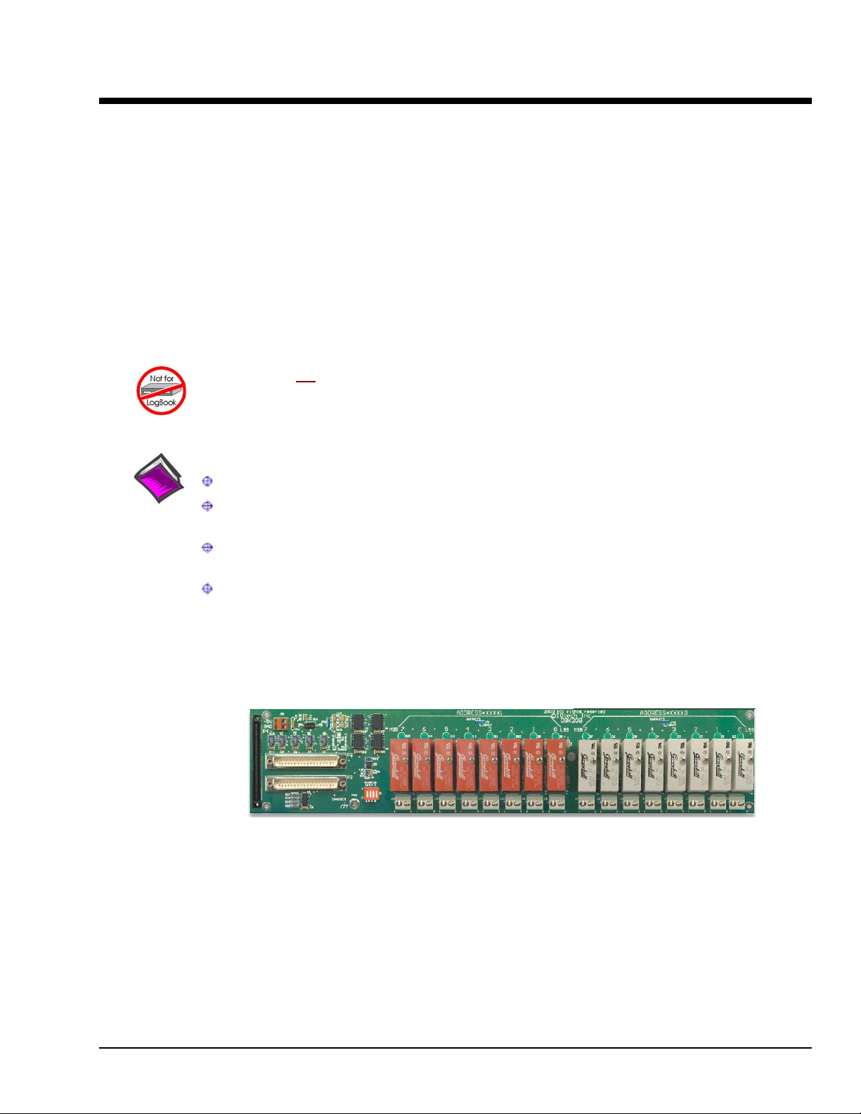
The DBK208 provides: (a) two P2 connectors, (b) footprints for sixteen optically-isolated SolidState-Relay (SSR) Modules, and (c) 16 dual-screw terminal blocks. DBK208 includes a 100-pin P4
connector for use with DaqBook/2000 Series Devices, DaqBoard/2000 Series Boards, and /2000c
Series Boards.
This product is not used with:
LogBook
DaqBook/100 Series devices
DaqBoard/100 (ISA-type) Series devices
Reference Notes:
In regard to calculating system power requirements refer to the DBK Basics section.
Chapter 2 includes pinouts for P1, P2, P3, and P4. Refer to pinouts applicable to your
system, as needed.
Overview
For a quick comparison of all DBK200 Series boards, refer to the DBK200 Series Matrix.
The matrix is located just before this DBK200 section.
Refer to the DaqBoard/2000 Series and cPCI DaqBoard/2000c Series User’s Manual
(p/n 1033-0901) or the DaqBook/2000 Series User’s Manual (p/n 1103-0901) for information
pertaining to those products, as needed.
DBK208 Carrier Board for Opto-22 Compatible Solid-State-Relays
DaqBoard/2000 Series and cPCI DaqBoard/2000c Series boards communicate [external from the host PC]
through a 100-pin P4 connector. The P1, P2, and P3 connectors discussed in association with these boards
are subset connectors of the 100-pin P4 connector. Chapter System Connections and Pinouts, includes
pinouts for P1, P2, P3, and P4.
The information included in this section, when combined with that found in the related DBK option cards
and modules subsections should enable you to set up your desired configuration.
DBK208 is a two-bank carrier board for optically-isolated Solid-State-Relay (SSR) modules. Each bank
supports up to eight digital I/O modules. The banks can be independently set as “input” or “output” via
jumpers (JP0 for Bank 0, and JP1 for Bank 1). The I/O modules are industry standard Opto-22 compatible,
5-volt logic level modules.
DBK Option Cards and Modules 987594 DBK208, pg. 1
Page 2
WARNING
Ensure that hard-wire emergency over-ride circuitry exists for all applications that
make use of dangerous switch-loads. Do not operate such switch-loads unless
emergency over-ride circuitry is present.
Note 1: DBK208 is not used with DaqBoard/2003.
Note 2: DBK208 can be used with DaqBook/200 and Daqboard/200 (ISA-type) series devices;
but should not be used with DaqBook/100 or DaqBoard/100 (ISA-type) series devices.
DBK208, pg. 2
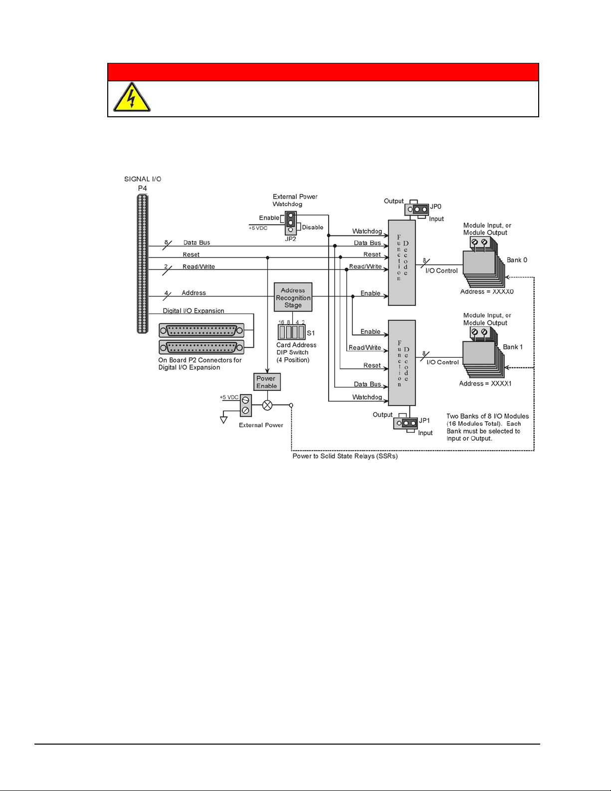
DBK208 Block Diagram
DBK208 boards are typically installed in NEMA-type panels; however, they may alternatively be installed
on DIN rails. Separate mounting instructions are included with Rack Mount Kit (part no. Rack-DBK-3)
and with DIN-rail Mount Kit (part no. DIN-DBK-1).
DBK208 is controlled digitally from the Daq device (DaqBook or DaqBoard) through one of two
connectors, as follows:
DaqBook/200 Series Devices – control is through the 37-pin P2 digital port of the DaqBook and one of two DBK208
P2 connectors.
DaqBoard/200 Series boards [ISA-type] - control is through the 37-pin P2 digital port of the DaqBoard and one of
the DBK208 P2 connectors.
DaqBook/2000 Series Devices, DaqBoard/2000 Series boards, and cPCI DaqBoard/2000c Series boards – control
originates in the board’s 100-pin P4 connector. Connection of these boards to DBK208 can be made directly or
indirectly as follows:
• Direct connection can be made from the 2000 series board’s 100-pin P4 connector to a DBK208’s P4
connector via a CA-195 cable.
Indirect connection can be made using one of the DBK200 Series P4-adapters that includes a 37-pin P2
•
connector (DBK201, DBK202, DBK203, DBK204, DBK206, DBK209, or another DBK208). CA-37
cables are used to connect from P2 to P2.
987594 DBK Option Cards and Modules
Page 3
Note that a single Daq-based data acquisition system can support up to 16 DBK208 boards, providing a
total of 256 channels. DBK208 boards contain two DB37 P2 connectors for the purpose of daisy-chaining
to other DBK208s or to other P2-supported devices.
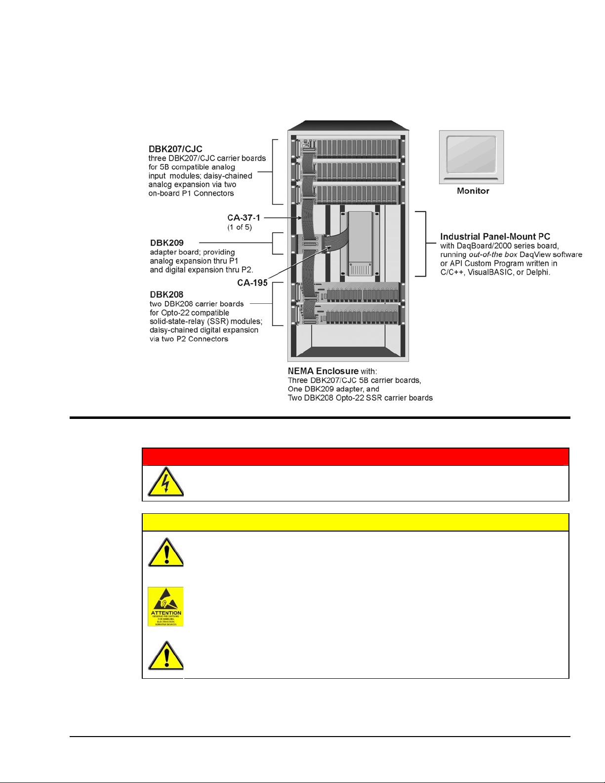
The following illustration is an example of a Data Acquisition System that includes two DBK208 boards
for digital I/O. The two DBK208 boards are daisy-chained to a DBK209 P2 connector. The DBK209 is
connected to a DaqBoard/2000 Series board via a CA-195 cable.
Warnings, Cautions, and Tips
Ensure that hard-wire emergency over-ride circuitry exists for all applications that
make use of dangerous switch-loads. Do not operate such switch-loads unless
emergency over-ride circuitry is present.
Turn off power to the host PC and externally connected equipment prior to connecting
cables or signal lines to the DBK. Electric shock or damage to equipment can result
even under low-voltage conditions.
Take ESD precautions (packaging, proper handling, grounded wrist strap, etc.)
Use care to avoid touching board surfaces and onboard components. Only handle
boards by their edges (or ORBs, if applicable). Ensure boards do not come into contact
with foreign elements such as oils, water, and industrial particulate.
Do not confuse connectors. Ensure that you only connect P1 I/Os to P1,
P2 I/Os to P2, and P3 I/Os to P3. Improper connection may result in equipment
damage.
WARNING
CAUTION
DBK Option Cards and Modules 987594 DBK208, pg. 3
Page 4

1. Provide raceways (protective wiring routes) for all external I/O wiring.
2. Keep external I/O wiring away from ribbon cables.
3. Keep external I/O wiring away from low-voltage signal wiring.
4. Provide approp riate strain-relief and physical restraint to ensure that the wiring is held securely in the
intended position, and without strain.
5. Ensure that all wiring with >5 0V potential is identified by the appropriate color cod es and that
warning labels are clearly visible.
6. Provide physical protection for the I/O interface board. The level of protection is dependent upon the
board’s operating environment.
Power
Partial DBK208
The DBK208 requires an external isolated 5 volt DC supply
with at least 0.25 amp current capacity. External power attaches
to the DBK208 via on-board screw terminal connections. The
board contains capacitors to filter input noise from the power
supply.
Over-current protection is provided by an on-board 0.5 amp
reset fuse in series with the 5 volt supply. Protection from
over-voltage and reverse polarity power conditions is provided
by a 6.8V zener diode.
DBK208, pg. 4
987594 DBK Option Cards and Modules
Page 5

External Power Watchdog
The External Power Watchdog is governed by the setting of the JP2 jumper. This jumper allows the user
to determine the behavior of the digital output latches in the event of a loss and recovery of the external
power supply.
With the jumper in the ENABLE position, the loss of external p ower will cause the output latches to be
reset into a high-impedance condition. Even with a recovery of the external power, all output modules will
be disabled until a write is done to the data bus. This setting is useful in an application that requires a
serial enabling of output loads.
With the jumper in the DISABLE position, the loss of external power will have no effect on the state or
continued control of the output latches. That is, data that is written to the output modules will continue to
be latches as normal. A recovery of the external power would then cause the output modules to reflect the
current state of the output latches. This setting is useful in the case where the operator halts the transfer of
data and turns off the external power on purpose and then wants the system to assume the same state upon
recovery of the external power.
The setting of the JP2 jumper has no effect on input modules with regards to external power. While a loss
of external power will result in corruption of the data b eing read, the data bus will be valid again
immediately upon the recovery of the external power. The default setting of the JP2 jumper is the
ENABLE position.
Operation
The DBK208 P2 expansion protocol makes use of a 4-bit dip switch (S1) to configure the board’s
addresses. Addresses are seen as XXXX + 0 for Bank 0’s set of eight modules and as XXXX + 1 for Bank
1’s set of eight modules, where the four Xs represent the DIP switch settings of 16 8 4 and 2. With all
four S1 micro-switches OFF (open), the first system board (designate as “0”) has Bank 0 registered as 0
and Bank 1 registered as 1. With S1’s micro-switch “2” closed, we would see Bank 0 registered as 2 and
Bank 1 registered as 3. The following table portrays the addressing scheme and includes DaqView
designations.
The following breakdown is provided to indicate the relationship of DaqView channels to DBK208 boards
and banks. More detailed information follows.
Simplified Channel-to-DBK208 Relationship
DBK Option Cards and Modules 987594 DBK208, pg. 5
Page 6

DBK208
Board #
0
1
2
3
4
5
6
7
8 ON
9 ON
10 ON
11 ON
12 ON ON
13 ON ON
14 ON ON ON
15 ON ON ON ON
Switch S1 Configurations
16 8 4 2 Bank 0 Bank 1 Expanded Digital I/O in
OFF OFF OFF OFF 0 1 P2 0-A P2 0-B
OFF OFF OFF
OFF OFF
OFF OFF
OFF
OFF
OFF
OFF
ON
ON ON
ON
ON
ON ON
ON ON ON
OFF OFF OFF 16 17 P2 4-A P2 4-B
OFF OFF
OFF
OFF
OFF OFF 8 9 P2 2-A P2 2-B
OFF
ON
ON ON
OFF OFF 24 25 P2 6-A P2 6-B
OFF
Address
ON
OFF 4 5 P2 1-A P2 1-B
ON
OFF 12 13 P2 3-A P2 3-B
ON
OFF 20 21 P2 5-A P2 5-B
ON
OFF 28 29 P2 7-A P2 7-B
2 3 P2 0-C P2 0-D
6 7 P2 1-C P2 1-D
10 11 P2 2-C P2 2-D
14 15 P2 3-C P2 3-D
18 19 P2 4-C P2 4-D
22 23 P2 5-C P2 5-D
26 27 P2 6-C P2 6-D
30 31 P2 7-C P2 7-D
Designation in DaqView
(see notes 2 & 3)
Async Digital I/O window
Channel
0
1
2
3
4
5
6
7
Notes: (1) Switch S1 settings are made physically on the DBK208 boards and are checked in DaqView (see the
following screen capture). The software aspect is detailed on the following page.
(2) The Digital Option Cards External Connection section of DaqView’s Configure System Hardware
window lists 8 channels (0 through 7) as shown in the following screen image.
(3) Each of the 8 channels can represent 2 DBK208 boards. For example, as seen in the table, System Board
0 and System Board 1 would both show up in DaqView’s channel 0.
(4) In the Async Digital I/O window, each active channel (representing 2 boards) has divisions of A, B, C,
and D. A represents Bank 0 of the first board. B represents Bank 1 of the first board.
C represents Bank 0 of the second board. D represents Bank 1 of the second board.
(5) Banks are selected to be “Input” or “Output” via jumpers. Jumper JP0 applies to Bank 0, JP1 applies to
Bank 1.
Logic outputs provide signals for clocking data to registers for the Opto-22 SSR type modules. On-board
jumpers (JP0 and JP1) are used to set the banks for “input” or “output.” The banks can be set
independently, however, all modules within a bank will have the same setting. For example, JP0 could be
set to “Input,” configuring all 8 modules of Bank 0 to Input; and JP1 could be set to “Output,” configuring
all Bank 1 modules to “Output.”
Each Opto-22 module has a 2-connector terminal block for signal connections.
DBK208, pg. 6
987594 DBK Option Cards and Modules
Page 7

Software Setup
Note: DBK208 is not applicable to LogBook or LogView.
To use DBK208 from within DaqView, you must first configure the DaqView software to match the
hardware setup.
1. From DaqView’s main window, select the Device pull-down menu.
2. Select Configure Hardware Settings.
The Digital Option Cards External Connection section of DaqView’s Configure System Hardware
window lists 8 channels (0 through 7) as shown in the following screen image.
3. Under Digital Option cards (on right side of screen), select DBK208. A DBK208 Configuration
Settings window will appear. The window includes a “Switch Settings” section (see following figure).
4. Select the S1 switch settings that apply to your configuration. In the above screen example
DaqView’s Digital Channel 0 consists of two boards. Note that no more than two DBK208 boards are
permitted per DaqView Channel. Both S1 check boxes are selected when two boards are used in a
channel.
5. Check (or uncheck) JP-0 and JP-1 to match your hardware. A checked jumper indicates that the
associated bank is digital Input. An unchecked jumper indicates Output. The first board in the
channel has its banks designated as P2 0-A and P2 0-B. The second board’s banks are designated as
P2 0-C and P2 0-D.
6. After S1, JP-0, and JP-1 settings are complete, click the OK button.
7. Select the Digital I/O icon from DaqView’s main window toolbar. The Async Digital I/O window will
appear.
With the P2 Digital I/O tab selected in the Async Digital I/O window, each active channel
(representing 2 boards) has divisions of A, B, C, and D.
• “A” represents the 8-bit Bank 0 of the first board.
• “B” represents the 8-bit Bank 1 of the first board.
• “C” represents the 8-bit Bank 0 of the second board.
• “D” represents the 8-bit Bank 1 of the second board.
DBK Option Cards and Modules 987594 DBK208, pg. 7
Page 8

Switch Settings
The switch settings must
agree with those on the
actual DBK208 board.
Refer to pages 5 and 6 of
this section for configuration details.
Configure System Hardware and DBK208 Configuration Settings Windows
For Digital Output
Ensure the JP0 and JP1
boxes are checked for each
port configured as Digital
Output.
For Digital Input
Ensure the JP0 and JP1
boxes are
each port configured as
Digital Input.
not checked for
DBK208, pg. 8
Async Digital I/O Window – P2 Digital I/O Tab Selected
In the above screen shot of the Digital I/O Window, channel 0 represents two DBK208 boards. The
first board consists of banks A and B, the second board consists of banks C and D. In this example all
four banks are seen as Input. The input determination was made by the physical positions of hardware
jumpers (JP0 and JP1) and software selections for JP-0 and JP-1, i.e., that for Digital Input they were
not checked.
Note: When Output is selected, hexadecimal values must be entered in the “O” block for the
applicable bank.
8. Upon completion of the configuration click the Execute button.
987594 DBK Option Cards and Modules
Page 9

DBK208 – Specifications
Name/Function: Carrier Board for Opto-22 Compatible Solid-State-Relays
Module Capacity: 16, Opto-22 Solid-State-Relays
Cable (optional): CA-37-×
DC Input Fuse: 0.5A, re-set type
Power Requirement: 5 VDC, regulated. 0.25 amp minimum.
Operating Environment:
Temperature: 0°C to 70°C
Relative Humidity: 95% RH, non-condensing
Connectors:
P4 – 100-pin connector provides for connection to a DaqBook/2000 Series device’s,
DaqBoard/2000 Series board’s or cPCI DaqBoard/2000c Series board’s
P4 connector via a CA-195 cable.
P2 – Two P2 (DB37) connectors provide for digital expansion via CA-37-x cable.
Screw Terminals – 16 sets of 2-connector blocks for I/O signals.
Isolation:
Channel-to-System: 500 V
Channel-to-Channel: 500 V
DBK Option Cards and Modules 987594 DBK208, pg. 9
Page 10

DBK208, pg. 10
987594 DBK Option Cards and Modules
 Loading...