

Page 1

DBK19 14-Channel Thermocouple Card
Overview …… 1
Hardware Setup …… 2
Card Connection …… 2
Card Configuration …… 3
DaqBook/100 Series & /200 Series and DaqBoard [ISA type] Configuration ……3
DaqBook/2000 Series and DaqBoard/2000 Series Configuration …… 3
Software Setup …… 3
DBK19 – Specifications …… 4
Reference Notes:
o Chapter 2 includes pinouts for P1, P2, P3, and P4. Refer to pinouts applicable to your
system, as needed.
o In regard to calculating system power requirements, refer to DBK Basics located near the
front of this manual.
o Refer to the Signal Management chapter for information regarding Two-Point
Calibration of a Temperature Measurement System.
Overview
DaqView Users: When a DBK19 is used with a /2000 Series Device, the Internal Clock Speed
should be set to 100 kHz as described in chapter 3, DBK Setup in DaqView.
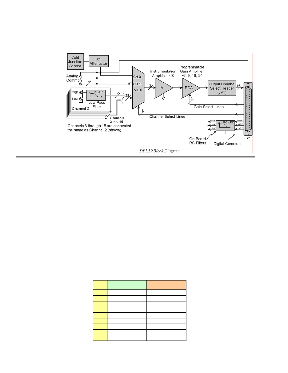
The DBK19 can attach to 14 thermocouples (T/C) for temperature measurements. The DBK19 features an
on-board cold junction sensor and a programmable-gain amplifier for measuring type J, K, T, E, N28, N14,
S, R, or B thermocouples. The table shows the temperature range for each thermocouple type.
T/C Type J K T E N28 N14 S R B
Temperature
Range °C
Temperature
Range °F
-200 to
760
-328 to
1400
-200 to
1260
-328 to
2300
-200 to
400
-328 to
752
-270 to
1000
-454 to
1832
-270 to
400
-454 to
752
0 to
1300
32 to
2372
0 to
1780
32 to
3236
0 to
1780
32 to
3236
0 to
1820
32 to
3308
True differential measurements of thermocouples require a bias current referenced to analog common;
therefore, resistors connect each input terminal to the analog common. Filter capacitors across each input
operate with input protection resistors to form single-pole RC low-pass filters.
Each DBK19 includes a cold-junction compensation circuit wired to channel 0. Channels 2 through 15
accept external thermocouples. The DBK19s can be used with other analog expansion cards and feature
screw terminals for direct connection. Up to 16 DBK19s can be attached to a single LogBook or a Daq
Device to measure up to 224 (16 × 14) temperatures.
DBK Option Cards and Modules 879795 DBK19, pg. 1
Page 2
Note: LogView and DaqView software includes functions for the conversion and linearization of
thermocouple readings into temperature data.
Programmers using Daq devices should refer to related sections in the Programmer’s Manual.
Hardware Setup
Card Connection
Connect the T/C input wires to the intended input terminals. The DBK19 uses screw terminals to connect
different types of thermocouples as well as several analog ground access points. Connections are provided
for 14 thermocouples.
Thermocouples have polarities that must be observed. Thermocouple types J, K, T, E, N28, N14, S, R and
B can be connected to DBK19 channels CH2 through CH15.
• CH0 is reserved for the cold-junction compensation sensor (factory installed).
• CH1 is permanently shorted to common to allow software-driven auto-zero to compensate for
Thermocouple wire is standardized and color-coded as shown in the table. T/Cs have a very small output.
Long T/C leads can pickup lots of noise. Use shielding as needed, and average several readings in
software to minimize noise effects.
After all connections are in place, secure wires to captive areas (pre-drilled holes) at the rear edge of the
board. Nylon tie wraps (not included) work well for this purpose.
temperature drift.
T/C
Type
J White Red
K Yellow Red
T Blue Red
E Violet Red
N28 Orange Red
N14 Orange Red
S Black Red
R Black Red
B Gray Red
(+) Lead to
Channel-Hi
(-) Lead to
Channel-Lo
DBK19, pg. 2 879795 DBK Option Cards and Modules
Page 3

Card Configuration
Assign a LogBook or Daq device channel number to the DBK19 card. Up to 16 DBK19s
can connect to a LogBook or a Daq device. (Optional DBK10 expansion card enclosure
may be used.) Since this is a daisy-chain interface, each card must have a unique channel
address.
To configure the card, locate the 16×2-pin header (labeled JP1) near the front of the
board. The 16 jumper locations on this header are labeled CH0 through CH15. Place the
jumper on the channel you wish to use. Only one jumper is used on a single card; each
card in the system must have a unique jumper setting.
DaqBook/100 Series & /200 Series and DaqBoard [ISA type] Configuration
Use of the DBK19 requires setting jumpers in DaqBooks/100 Series & /200 Series
devices
and DaqBoards [ISA type].
1. If not using auxiliary power, set the JP1 jumper for Analog Option Card Use,
also referred to as the expanded analog mode.
Note: The JP1 default position (above) is necessary to power the
interface circuitry of the DBK19 via the internal ±15
VDC power supply. If using auxiliary power (e.g., a
DBK32A or DBK33) you must remove both JP1 jumpers.
Refer to Power Requirements in the DBK Basics section
and to the DBK32A or DBK33 sections as applicable.
2. For DaqBook/100, DaqBook /112, and DaqBook /120 only,
place the JP4 jumper in the single-ended mode.
Note: Analog expansion cards convert all input signals to single-ended voltages referenced to analog
common.
DaqBook/2000 Series and DaqBoard/2000 Series Configuration
No jumper configurations are required for these /2000 series devices.
Software Setup
Reference Notes:
o DaqView users - Refer to chapter 3, DBK Setup in DaqView.
o LogView users - Refer to chapter 4, DBK Setup in LogView.
o DBK19 Calibration Disk – Each DBK19 card is shipped with a calibration disk with constants
used to correct gain and offset errors inherent in the hardware. This calibration is done
automatically by DaqView and LogView. Refer to the readme.txt file on the disk.
o Refer to the Signal Management chapter for information regarding Two-Point Calibration of a
Temperature Measurement System.
DaqView Users: When a DBK19 is used with a /2000 Series Device, the Internal Clock Speed should
be set to 100 kHz as described in chapter 3, DBK Setup in DaqView.
The DBK19 selection allows the user to define the thermocouple types by using the Type column of the
analog input spreadsheet.
Each DBK19 card is shipped with a calibration disk with constants used to correct gain and offset errors
inherent in the hardware. This gain and offset calibration is done automatically by DaqView and
LogView.
See the DBK19 readme.txt file on the disk shipped with the board for details on creating this file.
DBK Option Cards and Modules 879795 DBK19, pg. 3
Page 4

DBK19 - Specifications
Name/Function: High-Accuracy Thermocouple Card
Connector: DB37 male mates with P1 pinouts. Thermocouples attach to on-board screw terminals.
Thermocouple Types: J, K, S, T, E, B, R, N
Gain Ranges: ×60, ×90, ×180, ×240
7Inputs:
14 differential thermocouples
1 cold-junction compensation
1 auto zero
Cold Junction Sensor Output: 100mV/°C
Voltage Ranges Gains:
0 to 80 mV @ ×60
0 to 50 mV @ ×90
0 to 25 mV @ ×180
0 to 20 mV @ ×240
0 to ±10 mVDC
Input Impedance: 20 KΩ
Input RC Filter: -3 dB Frequency: 15.9 kHz
Gain Accuracy:
Uncalibrated: 0.15%
Calibrated: 0.02%
Maximum Input Voltage: 35 VDC
CMRR (Input Stage): 110 dB type DC to 60 Hz
Offset: Software compensated
Thermocouple Type/Range/Accuracy/Resolution: refer to the following table
Range Accuracy Resolution
Type Min Max (<0°C) (>0°C) 12-bit <0°C 12-bit >0°C 16-bit <0°C 16-bit >0°C
J -200°C 760°C 0.6°C 0.6°C 1.2°C 0.5°C 0.1°C 0.1°C
K -200°C 1260°C 1.6°C 1.0°C 1.1°C 0.8°C 0.1°C 0.1°C
T -200°C 400°C 1.4°C 0.8°C 0.8°C 0.3°C 0.1°C 0.1°C
E -270°C 1000°C 1.4°C 0.9°C 1.6°C 0.7°C 0.1°C 0.1°C
N28 -270°C 400°C 0.8°C 0.8°C 1.0°C 1.0°C 0.1°C 0.1°C
N14 0°C 1300°C — 1.0°C — 5.0°C — 5.0°C
S 0°C 1780°C — 1.6°C — 1.3°C — 0.1°C
R 0°C 1780°C — 1.6°C — 1.7°C — 0.1°C
B 0°C 1820°C — 1.8°C — 1.5°C — 0.1°C
Thermocouple Reference
DBK19, pg. 4 879795 DBK Option Cards and Modules
 Loading...