

Page 1

DBK12 and DBK13 16-Channel Analog Input Multiplexer Cards
DBK12 – Low Gain Programmable Card
DBK13 – High Gain Programmable Card
Overview …… 1
Hardware Setup …… 2
Card Connection …… 3
Card Configuration …… 3
DaqBook/100 Series & /200 Series and DaqBoard [ISA type] Configuration …… 4
DaqBook/2000 Series and DaqBoard/2000 Series Configuration …… 4
Software Setup …… 4
DBK12 – Specifications …… 5
DBK13 – Specifications …… 5
Reference Notes:
o Chapter 2 includes pinouts for P1, P2, P3, and P4. Refer to pinouts applicable to your
system, as needed.
o In regard to calculating system power requirements, refer to DBK Basics located near
the front of this manual.
Overview
DBK12
DBK13
Both the DBK12 and DBK13 provide 16 single-ended, or 16 differential, analog inputs.
The DBK12 ’s amplifier offers ×1, 2, 4, or 8 gain (programmable per channel). These gains can be
combined with:
LogBook: the standard LogBook gains of 1, 2, 4, 8, 16, 32, and 64 to yield gains of 1, 2, 4, 8, 16,
32, 64, 128, 256, and 512.
Daq devices: the standard Daq device gains of 1, 2, 4, or 8 to yield gains of 1, 2, 4, 8, 16, 32, and
64.
The DBK amplifier offers ×1, 10, 100, or 1000 gain (programmable per channel). These gains can be
combined with:
LogBook: the standard LogBook gains of 1, 2, 4, 8, 16, 32, and 64 to yield gains of 1, 2, 4, 8, 10,
16, 20, 32, 40, 64, 80, 100, 160, 200, 320, 400, 640, 800, and 1000.
Daq devices: the standard Daq device gains of 1, 2, 4, or 8 for net gains of 1, 2, 4, 8, 10, 20, 40, 80,
100, 200, 400, 800, 1000.
DBK Option Cards and Modules 879895 DBK12 and DBK13, pg. 1
Page 2
Up to 16 such cards can be attached to one of the 16 base channels for 256 single-ended or differential
inputs. The scan sequencer can directly program the expansion cards to scan external signals at the same
10 µs/channel rate as on-board channels.
Note: DBK12 and DBK13 use the same printed circuit board and look quite similar. If the label becomes
unreadable, you can distinguish them as follows: the U6 integrated circuit is a PGA203 in DBK12;
but a PGA202 in DBK13.
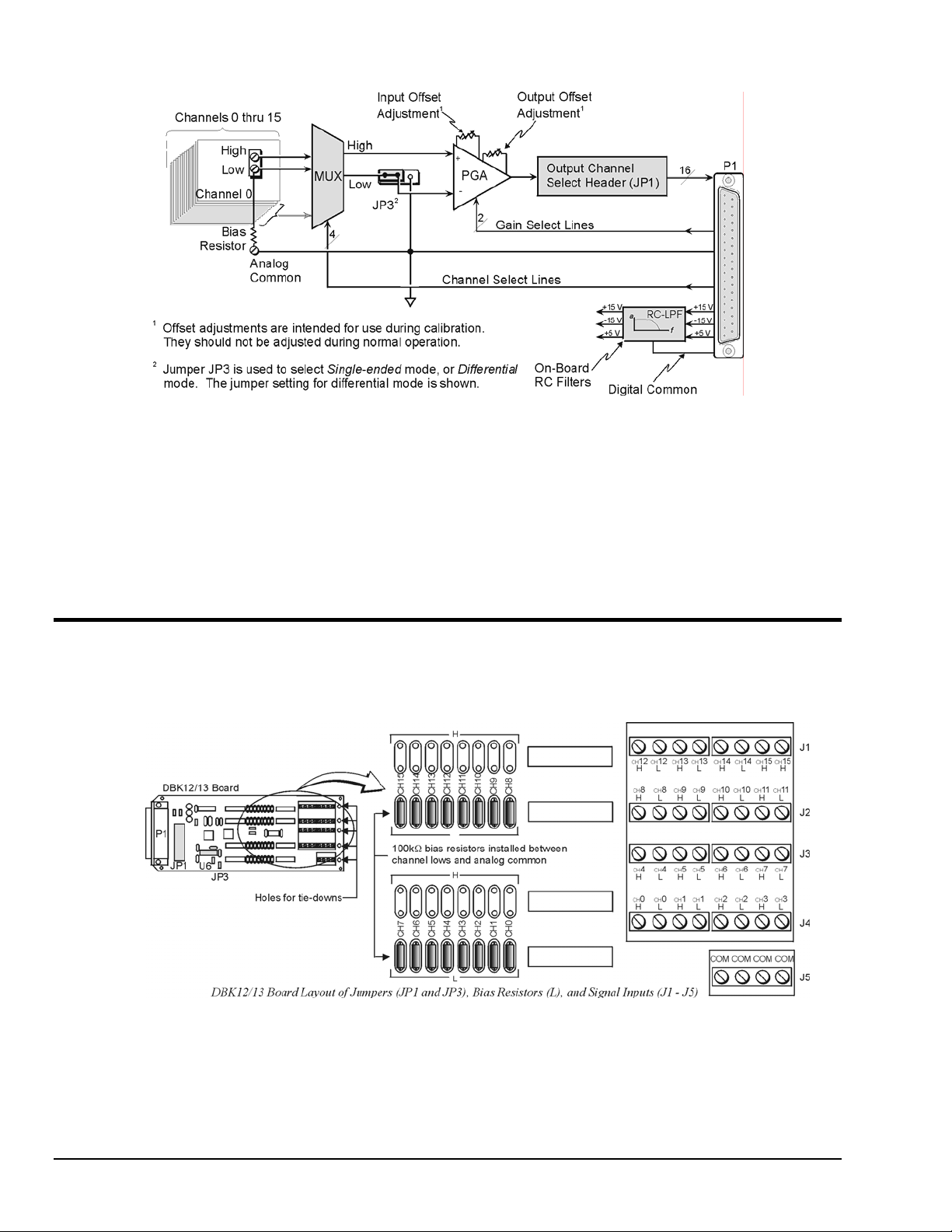
Hardware Setup
To set up the card, you may need to refer to the following board layout. The layout can be used for both
DBK12 and DBK13.
DBK12 and DBK13 Block Diagram
DBK12 and DBK13, pg. 2 879895 DBK Option Cards and Modules
Page 3

Card Connection
DBK12 and DBK13 are equipped with screw terminal connectors for easy access to all of the analog
inputs, as well as several analog ground access points. Connections are provided for 16 single-ended or
16 differential inputs. On board, there are factory-installed, 100 KΩ bias resistors in the L locations for
each channel; these resistors can be removed if desired. (The H locations have no factory-installed
resistors).
1. For single-ended operation, connect the signal’s high end to the high input of the desired channel
and the low end to analog common (J5).
2. For differential operation, connect the signal’s high end to the high input and the low end to the low
input of the desired channel. When using differential input, ground referencing to analog common is
important for accuracy. If necessary, use bias resistors. The two differential measurement
configurations (floating and referenced) are discussed in the Signal Management chapter.
3. After all connections are in place, secure wires to the card at the captive areas at the end of the card.
Nylon tie wraps work well for this purpose.
Card Configuration
Factory Default: Input mode – Single-ended
A path to analog common must exist, either by direct connection or through bias
resistors.
The two variables of card configuration are input mode to the card and channel output to the LogBook or
the Daq device.
1. Using the onboard jumper, JP3, set the signal input mode (see figure).
The jumper and its SE (Single-Ended) and DIFF (Differential) positions
are clearly identified on the board overlay.
• For single-ended inputs, place the jumper in the SE position.
• For differential inputs, place the jumper in the DIFF position.
2. To configure the channel, locate the 16×2-pin header (JP1) located near
the front of the board. JP1’s 16 jumper locations (CH0 through CH15)
match corresponding base channels. Place the jumper on the channel
you wish to use.
Only one channel can be selected on a single card; and all cards in a
daisy-chain must have unique jumper settings. Up to sixteen DBK12s
(or DBK13s) may be connected to your LogBook or to your Daq device.
An optional DBK10 enclosure may be used.
Bias resistors are now factory-installed between the channel lows and analog
common. If you have an early version board, you can still install the bias
resistors. The use of bias resistors is discussed in the Signal Management
chapter.
DBK12, DBK13
Configurations
DBK Option Cards and Modules 879895 DBK12 and DBK13, pg. 3
Page 4

DaqBook/100 Series & /200 Series and DaqBoard [ISA type] Configuration
Use of DBK12 or DBK13 requires the following setup steps for DaqBook/100 Series & /200 Series
devices and DaqBoard [ISA type] applications.
1. If not using auxiliary power, place the JP1 jumper in the expanded analog mode.
Default Configuration Settings for DBK12 and DBK13
Note: These jumpers are located in the DaqBook/100 Series & /200 Series devices and
DaqBoard [ISA-Type] units.
The JP1 default position, indicated in the above figure, is necessary to power the interface circuitry
of the DBK12 or DBK13 via the internal ±15 VDC power supply. If using auxiliary power (e.g. a
DBK32A or DBK33), you must remove both JP1 jumpers. Refer to Power Requirements in the
DBK Basics section and to the DBK32A and DBK33 sections as applicable.
2. For DaqBook/100, DaqBook /112, and DaqBook /120 only, place the JP3 jumper in either the
unipolar or bipolar mode as needed (bipolar shown).
3. For DaqBook/100, DaqBook /112, and DaqBook /120 only, place the JP4 jumper in the
DaqBook/DaqBoard in single-ended mode.
Note: Analog expansion cards convert all input signals to single-ended voltages referenced to
analog common.
DaqBook/2000 Series and DaqBoard/2000 Series Configuration
No jumper configurations are required for these 2000 series devices.
Software Setup
Reference Notes:
o DaqView users - Refer to chapter 3, DBK Setup in DaqView.
o LogView users - Refer to chapter 4, DBK Setup in LogView.
DBK12 and DBK13, pg. 4 879895 DBK Option Cards and Modules
Page 5

DBK12 – Specifications
Name/Function: Analog Multiplexing Card (Low Gain)
Output Connector: DB37 male, mates with P1
Input Connector: Screw terminals
Gain Ranges: ×1, ×2, ×4, ×8
Inputs: 16 differential or single-ended
Voltage Range: 0 to ±5 VDC bipolar; 0 to 10 V unipolar
Input Impedance: 100 MΩ (in parallel with switched 150 pF)
Gain Accuracy: ±0.05% typ, ±0.25% max
Maximum Input Voltage: ±35 VDC
Slew Rate: 20 V/µs typ, 10 V/µs min
Settling Time: 2 µs to 0.01%
CMRR: 80 dB min
Non-Linearity: 0.002% typ, 0.015% max
Bias Current: 150 pA, 0.2 µA max
Offset Voltage: ±(0.5 + 5/G) mV typ; ±(2.0 + 24/G) mV max
Offset Drift: ±(3 + 50/G) µV/°C typ; ±(2.0 + 24/G) µV/°C max
(switch selectable as a group)
DBK13 – Specifications
Name/Function: Analog Multiplexing Card (High Gain)
Output Connector: DB37 male, mates with P1
Input Connector: Screw terminals
Gain Ranges: ×1, ×10, ×100, ×1000
Inputs: 16 differential or single-ended (switch selectable as a group)
Voltage Range: 0 to ±5 VDC bipolar; 0 to 10 V unipolar
Input Impedance: 100 MΩ (in parallel with switched 150 pF)
Gain Accuracy: ±0.05% typ @ G < 1000
±0.25% max @ G < 1000
±0.10% typ @ G = 1000
±100% max @ G = 1000
Maximum Input Voltage: ±35 VDC
Slew Rate: 20V/µs typ, 10V/µs min
Settling Time: 2 µs to 0.01% @ G < 1000
10 µs to 0.01% @ G = 1000
CMRR: 80 dB @ G=1 min
86 dB @ G=10 min
92 dB @ G=100 min
94 dB @ G=1000 min
Non-Linearity: 0.002% typ @ G < 1000
0.015% max @ G < 1000
0.02% typ @ G = 1000
0.06% max @ G = 1000
Bias Current: 150 pA typ; 0.2 µA @ 25ºC max
Offset Voltage: ±(0.5 + 5/G) mV @ 25ºC typ;
±(2.0 + 24/G) mV @ 25ºC max
Offset Drift: ±(3 + 50/G) µV/ºC typ; ±(12 + 240/G) µV/ºC max
DBK Option Cards and Modules 879895 DBK12 and DBK13, pg. 5
 Loading...