

Page 1

DataShuttle and DynaRes
for Data Acquisition and Control
User’s Manual
the smart approach to instrumentation
™
IOtech, Inc.
25971 Cannon Road
Cleveland, OH 44146-1833
Phone: (440) 439-4091
Fax: (440) 439-4093
E-mail (sales): sales@iotech.com
E-mail (post-sales): productsupport@iotech.com
Internet: www.iotech.com
DataShuttle and DynaRes
Users Manual
for Data Acquisition and Control
p/n
1051-0901
Rev.
2.0
© 1998, 1999, 2000 by IOtech, Inc. November 2001 Printed in the United States of America
Page 2

Page 3
Warranty Information
Your IOtech warranty is as stated on the product warranty card. You may contact IOtech by phone,
fax machine, or e-mail in regard to warranty-related issues.
Phone: (440) 439-4091, fax: (440) 439-4093, e-mail: sales@iotech.com
Limitation of Liability
IOtech, Inc. cannot be held liable for any damages resulting from the use or misuse of this product.
Copyright, Trademark, and Licensing Notice
All IOtech documentation, software, and hardware are copyright with all rights reserved. No part of this product may be
copied, reproduced or transmitted by any mechanical, photographic, electronic, or other method without IOtech’s prior
written consent. IOtech product names are trademarked; other product names, as applicable, are trademarks of their
respective holders. All supplied IOtech software (including miscellaneous support files, drivers, and sample programs)
may only be used on one installation. You may make archival backup copies.
FCC Statement
IOtech devices emit radio frequency energy in levels compliant with Federal Communications Commission rules (Part 15)
for Class A devices. If necessary, refer to the FCC booklet How To Identify and Resolve Radio-TV Interference Problems
(stock # 004-000-00345-4) which is available from the U.S. Government Printing Office, Washington, D.C. 20402.
CE Notice
Many IOtech products carry the CE marker indicating they comply with the safety and emissions standards of the
European Community. As applicable, we ship these products with a Declaration of Conformity stating which
specifications and operating conditions apply.
Warnings, Cautions, Notes, and Tips
Refer all service to qualified personnel. This caution symbol warns of possible personal injury or equipment damage
under noted conditions. Follow all safety standards of professional practice and the recommendations in this manual.
Using this equipment in ways other than described in this manual can present serious safety hazards or cause equipment
damage.
This warning symbol is used in this manual or on the equipment to warn of possible injury or death from electrical
shock under noted conditions.
This ESD caution symbol urges proper handling of equipment or components sensitive to damage from electrostatic
discharge. Proper handling guidelines include the use of grounded anti-static mats and wrist straps, ESD-protective
bags and cartons, and related procedures.
This symbol indicates the message is important, but is not of a Warning or Caution category. These notes can be of
great benefit to the user, and should be read.
In this manual, the book symbol always precedes the words “Reference Note.” This type of note identifies the location
of additional information that may prove helpful. References may be made to other chapters or other documentation.
Tips provide advice that may save time during a procedure, or help to clarify an issue. Tips may include additional
reference.
Specifications and Calibration
Specifications are subject to change without notice. Significant changes will be addressed in an addendum or revision to
the manual. As applicable, IOtech calibrates its hardware to published specifications. Periodic hardware calibration is
not covered under the warranty and must be performed by qualified personnel as specified in this manual. Improper
calibration procedures may void the warranty.
Quality Notice
IOtech has maintained ISO 9001 certification since 1996. Prior to shipment, we thoroughly test our products and
review our documentation to assure the highest quality in all aspects. In a spirit of continuous improvement, IOtech
welcomes your suggestions.
Page 4

Page 5

Table of Contents
1 - Introduction & Installation of the
DataShuttle
Introduction …… 1-1
General Information …… 1-1
Development System …… 1-1
Expandability …… 1-1
Ranges/ Units of Measure …… 1-1
Data Presentation …… 1-2
Dynamic Resolution …… 1-2
Features and Configurations …… 1-3
For More Information …… 1-4
System Requirements …… 1-4
Hardware …… 1-4
Software Environment …… 1-4
Package Contents …… 1-4
DataShuttle Model Variations …… 1-4
DataShuttle-GP …… 1-4
DataShuttle-RTD …… 1-5
DataShuttle-TC …… 1-6
DataShuttle-5B …… 1-6
Installing Your DataShuttle …… 1-7
Physical Installation …… 1-8
To Install a DataShuttle …… 1-8
Single Unit Installation …… 1-8
Multiple Unit Installation …… 1-8
Printer Installation …… 1-9
Keyboard Adapter Installation …… 1-9
Next Steps …… 1-9
2 - DataShuttle - Technical Notes
Block Diagram …… 2-1
EDITCAL …… 2-2
Auxiliary Components …… 2-3
Starting EDITCAL …… 2-3
Analog Components …… 2-3
Instructions for Installing Components …… 2-3
Power Supplies …… 2-4
Examples …… 2-5
Example 1: Current Sense Resistor …… 2-5
Example 2: 3-Wire RTD Components …… 2-5
Example 3: Ground loops …… 2-6
Wiring Analog Outputs on the
DataShuttle …… 2-6
Current Outputs …… 2-7
Digital Components …… 2-8
Installing Digital Modules …… 2-8
Installing Pull-up Resistors …… 2-8
Installing Current Limiting Resistors …… 2-9
Counter/Timer …… 2-9
Counter/Timers lines available on the
DataShuttle …… 2-9
Troubleshooting: Installation …… 2-9
If You Need Customer Support …… 2-10
Troubleshooting: Operation …… 2-11
Hints …… 2-11
Operating Qs and As …… 2-11
Before Calling Customer Support …… 2-12
Product Specifications …… 2-13
Accuracy DataShuttle-16 Accuracy &
Resolution- …… 2-13
DataShuttle- 16 Thermocouple
Accuracy …… 2-13
Cold Junction Temperature Differential …… 2-14
DataShuttle-16 RTD Accuracy …… 2-14
Input Impedance …… 2-15
Noise Rejection …… 2-15
DataShuttle Noise Rejection …… 2-15
Common Mode Range …… 2-15
Input Protection …… 2-15
Resolution/Scan Rate …… 2-15
DataShuttle-16 Resolution And
Scan Rate …… 2-15
Analog Input …… 2-16
For the Analog Input Terminals on the
DataShuttle …… 2-16
Digital Input/Output …… 2-16
For the Digital Input/Output Termination on the
DataShuttle …… 2-16
Counter/Timer …… 2-16
Analog Output …… 2-16
DataShuttle-AO Resolution And
Accuracy …… 2-16
General Information …… 2-17
General Specifications of the
DataShuttle …… 2-17
General Specifications of the DS-5B
Models …… 2-17
3 - Introduction to the DynaRes
General Information …… 3-1
Development System …… 3-1
Expandability …… 3-1
Ranges/Units of Measure …… 3-1
Data Presentation …… 3-2
Dynamic Resolution …… 3-2
Features and Configurations …… 3-3
For More Information …… 3-3
DynaRes System Requirements …… 3-4
Hardware …… 3-4
Software Environment …… 3-4
Page 6

4 - Installing the DynaRes
6 - Introduction to Terminal Panels
Overview …… 4-1
Verifying DynaRes Switch Settings …… 4-1
Single Board …… 4-1
Multiple Boards …… 4-1
Previously in Use …… 4-2
Physical Board Installation …… 4-2
Terminal Panel Connections …… 4-2
Physical Installation …… 4-3
To Install the DynaRes Board …… 4-3
Next Steps …… 4-3
Measuring Current …… 4-4
Setting the Board Number Switch …… 4-4
Multiple Boards …… 4-4
Single Board …… 4-4
Disabling Boards …… 4-4
Setting the Switch …… 4-4
To Set the Board Number Switch …… 4-4
Setting the Base Address …… 4-5
Setting DynaRes Base Address …… 4-5
To Set the Base Address …… 4-5
DynaRes Base Address Switch Additive
Values …… 4-5
Base Address Settings …… 4-6
Possible DynaRes Base Address
Settings …… 4-6
Changing Hardware Interrupts …… 4-6
5 - DynaRes - Technical Notes
Overview …… 5-1
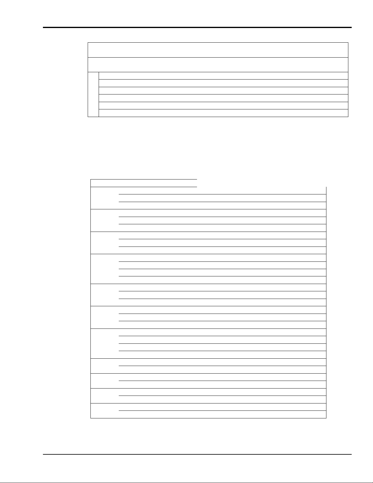
Pin Assignments …… 5-1
Block Diagram …… 5-2
Recalibration …… 5-3
Factory Methods …… 5-3
Recalibration …… 5-3
EDITCAL Utility …… 5-3
Starting Editcal …… 5-3
EDITCAL Selections …… 5-3
To Select a Function …… 5-3
Troubleshooting: Installation …… 5-4
If You Need Customer Support …… 5-4
Troubleshooting: Operation …… 5-5
Hints …… 5-5
Operating Qs And As …… 5-5
If You Need Customer Support …… 5-5
Product Specifications:
DynaRes 8/16 …… 5-6
Accuracy DynaRes 8/16 General
Conditions …… 5-6
DynaRes 8/16 Thermocouple Accuracy …… 5-7
DynaRes 8/16 RTD Accuracy …… 5-7
Stability …… 5-8
DynaRes 8/16 STABILITY …… 5-8
Input Impedance …… 5-8
Noise Rejection …… 5-8
DynaRes 8/16 Noise Rejection …… 5-8
Common Mode Range …… 5-8
Input Protection …… 5-8
Resolution/Scan Rate …… 5-9
DynaRes 8/16 Resolution And Scan Rate …… 5-9
Digital I/O Channels …… 5-9
Counter/Timer …… 5-9
DynaRes 8/16 Ultra Current
Consumption …… 5-10
General Information …… 6-1
Features …… 6-1
Package Contents …… 6-1
Types of Panels …… 6-1
Physical Installation …… 6-1
To Install a Terminal Panel …… 6-2
Terminal Panel Cross Reference …… 6-2
Types of Terminal Panels …… 6-2
T31 Terminal Panel …… 6-2
T71 Terminal Panel …… 6-3
Reference Tables …… 6-4
T31 Pin Connectors …… 6-4
Functions of the T31 Terminal Panels Pin
Connectors …… 6-4
T71 Pin Connectors …… 6-4
Functions of the T71 Terminal Panel Pin
Connectors …… 6-4
Auxiliary Analog and Digital
Components …… 6-5
Auxiliary Components …… 6-5
Examples …… 6-6
Example 1: Current sense resistor …… 6-6
Example 2: 3-Wire RTD components …… 6-7
Example 3: Ground loops …… 6-7
Digital Auxiliary Components …… 6-8
Installing Digital Modules …… 6-8
Installing Pull-up Resistors …… 6-9
Troubleshooting Q & A …… 6-9
Product Specifications …… 6-10
Accuracy …… 6-10
Cold Junction Compensation Error …… 6-10
Cold Junction Temperature Differential …… 6-10
Thermocouple Calibration Numbers …… 6-10
Digital Input/Output …… 6-10
For the Digital I/O Termination on All Terminal
Panel Types …… 6-10
On T31 Terminal Panels Only …… 6-10
On T71 Terminal Panels Only …… 6-11
General Conditions …… 6-11
Terminal Panel Power Supply
Consumption …… 6-11
7 - Introduction to the ACAO Board
General Information …… 7-1
Development System …… 7-1
Expandability …… 7-1
Ranges/Units of Output …… 7-1
Data Presentation …… 7-1
Features and Configurations …… 7-2
For More Information …… 7-2
System Requirements …… 7-2
Hardware …… 7-2
Software Environment …… 7-2
Page 7

8 - Installing the ACAO
Overview …… 8-1
Verifying ACAO Switch Settings …… 8-1
Single Board …… 8-1
Multiple Boards …… 8-1
Previously In Use …… 8-2
Physical Board Installation …… 8-2
Terminal Panel Connections …… 8-2
Physical Installation …… 8-3
To Install the ACAO Board …… 8-3
Setting the Voltage/Current Switches …… 8-3
Setting the Switches …… 8-3
To Set the Voltage/Current Switches …… 8-3
V/C Switch Settings for Analog Output
Channels …… 8-4
Next Steps …… 8-4
Setting the Board Number Switches …… 8-4
Multiple Boards …… 8-4
Single Board …… 8-5
Disabling Board …… 8-5
Setting the Switch …… 8-5
To Set the Board Number Switches …… 8-5
ACAO Board Number Switch Settings …… 8-6
Setting the Base Address …… 8-6
Setting ACAO Base Address …… 8-6
To Set the Base Address …… 8-6
ACAO Base Address Switch Additive
Values …… 8-7
Base Address Settings …… 8-7
Possible ACAO Base …… 8-7
9 - ACAO Analog Output & Control Board
Technical Notes
Overview …… 9-1
Recalibration …… 9-2
Factory Methods …… 9-2
Recalibration …… 9-2
Editing Calibration Files …… 9-3
CALOUT.DAT …… 9-3
Editcal Utility …… 9-3
Reconstructing Calibration Files …… 9-3
Multiple Boards/Panels …… 9-4
Calibration File Format …… 9-4
Analog Output Calibration File …… 9-4
Content of CALIB.DAT …… 9-4
CALOUT.DAT Notes …… 9-5
Reconstructing A Lost Calibration
File …… 9-5
Using EDITCAL …… 9-5
Starting EDITCAL …… 9-5
To Start Up EDITCAL.EXE …… 9-5
EDITCAL Selections …… 9-6
To Select a Function …… 9-6
Troubleshooting: Installation …… 9-6
Troubleshooting: Operation …… 9-7
Operating Qs And As …… 9-7
If you Need Customer Support …… 9-7
Product Specifications …… 9-8
Analog Outputs …… 9-8
Analog Output Ranges …… 9-8
Resolution …… 9-8
Speed …… 9-8
Maximum/Minimum Output …… 9-8
In Voltage Output Mode …… 9-8
In Current Output Mode …… 9-8
Accuracy ACAO General Conditions
Accuracy …… 9-8
Stability …… 9-8
In Voltage Output Mode …… 9-8
In Current Output Mode …… 9-9
Digital I/O Channels …… 9-9
Auxiliary Power Output …… 9-9
Auxiliary Power Output For The ACAO …… 9-9
10 Volt Reference …… 9-9
General Conditions …… 9-9
General Specifications of the ACAO …… 9-9
ACAO Power Consumption …… 9-9
10 - QuickLog Introduction
General Information …… 10-1
What You Need …… 10-1
System Requirements …… 10-1
Minimum Requirements …… 10-1
Setting Up QuickLog …… 10-2
Starting the Installation …… 10-2
For Computers Running Windows 3.x …… 10-2
For Computers Running Windows 95/98 ……10-2
Setup Summary …… 10-2
Completing Setup …… 10-2
Specifications …… 10-3
Meter Display Screens …… 10-3
Chart Display Screen …… 10-3
Logging …… 10-3
DDE …… 10-3
General Configuration …… 10-3
I/O Configuration By Channel …… 10-4
Chart Configuration …… 10-4
11 - Getting Started with QuickLog
General Information …… 11-1
File Menu …… 11-1
Edit Menu …… 11-1
Options Menu: General …… 11-2
Options Menu: Inputs …… 11-3
Options Menu: Output Meters …… 11-3
Options Menu: Chart …… 11-3
Chart Menu …… 11-4
Run Menu …… 11-4
Window Menu …… 11-4
Calibration Menu …… 11-4
Help Menu …… 11-4
Page 8

12 - Applications Primer
Applications Reference …… 12-1
Connection Types …… 12-1
Analog Input & Output Applications …… 12-1
Digital I/O Applications …… 12-1
Sensor Connections …… 12-2
Single-Ended vs. Differential
Connections …… 12-2
Auxiliary Power Output & Voltage
Reference …… 12-2
Auxiliary Components …… 12-2
Digital Connections …… 12-2
Special Note For Thermocouple
Applications …… 12-3
13 - Analog Input & Output
Analog Input & Output …… 13-1
Thermocouples …… 13-1
Thermocouple Types …… 13-3
Supported Product Thermocouple
Ranges …… 13-3
Strain Gages …… 13-4
Piezoelectric Sensors …… 13-5
Audio …… 13-6
RTDs …… 13-7
RTD Ranges & Resolution …… 13-8
RTD Accuracy …… 13-9
Current …… 13-10
High Voltage Divider …… 13-11
Voltage Output …… 13-11
Current Output …… 13-12
Glossary
14 - Digital I/O
Digital Input & Output …… 14-1
Common Applications …… 14-1
High Power Optically Isolated Digital
Output …… 14-1
High Power Optically Isolated Digital
Input …… 14-2
Pulse Counting …… 14-4
Cascaded Counter/Timers …… 14-4
Frequency/Rate Measurement …… 14-5
Appendix A - Thermocouple Application
Tips
Page 9

Introduction & Installation of the DataShuttle 1
Introduction
Thank you for selecting the DataShuttle for your project.
Our primary objective is to provide you with data acquisition systems that are easy to install, operate, and
maintain. We also strive to furnish the performance you need at the lowest overall cost. The benefits for you
are increased productivity, data you can count on, and, of course, meeting your budget.
We manufacture the DataShuttle as an enhancement product that readily plugs into the parallel port
of an IBM, or compatible, desktop or portable computer.
The product’s high noise rejection, input protection to withstand as much as 50 Volts, and guaranteed long
term stability make it ideal both for the laboratory and for harsh industrial environments. With its parallel
port interface, built-in terminal panel, and compact, light size, the DataShuttle is also completely portable,
providing for a quick and easy set-up in both in-house labs and remote test sites.
Using the DataShuttle together with our graphical interface application software (such as DASYLab
or QuickLog™), you can easily and very quickly implement a broad spectrum of research and commercial
tasks, in a variety of settings. You can, for example,
•
Display, and log data to disk for later analysis,
•
Measure temperature, pressure, flow and most other analog inputs from sensors and instruments,
•
Capture maximums, minimums, averages, or differences of measurements,
•
Monitor and control processes,
•
Set alarm limits on any input,
•
Control devices at preset levels (fans, pumps, heaters, etc.),
•
Control devices from digital input (from switches or TTL signals), and
•
Gather data unattended.
®
You can use the system interactively, operating controls or modifying your setup while the system is
running.
General Information
Development System
People who write their own software (rather than using an off-the-shelf application) can employ the
Analog Connection Windows Development System™ hardware driver. This can address all features
of the unit from within a program they design and code for their specific purpose.
Expandability
All DataShuttles have eight differential analog input channels and 8 digital input/output lines. You can add
one DataShuttle at a time to your computer, for as many as 15 units with a total of 120 analog input
channels and 120 digital I/Os.
Ranges/ Units of Measure
The six input ranges of the DataShuttle span from 50 milliVolts through 10 Volts DC, making it capable of
accepting data from almost any sensor. In addition, You can install a resistor, making the DataShuttle
capable of DC current measurements.
Its high accuracy makes the DataShuttle ideal for precise evaluations in the laboratory or field.
DataShuttle and DynaRes
11-13-01
Introduction & Installation of the DataShuttle 1-1
Page 10
The DataShuttle together with our software – such as DASYLab or QuickLog PC – make it easy to specify
engineering units (degrees, volts, milliAmperes, etc.) for measurements, as well as which ranges to use.
(You can measure temperature, for example, by selecting from among 11 different thermocouple types,
or from a variety of resistance temperature devices – RTDs. With the application software, the process
simply consists of selecting the type of sensing device from a menu – the driver itself automatically handles
cold junction compensation and linearization.)
Data Presentation
The combination of hardware and application software (DASYLab or QuickLog PC) enables both
the display of data on the screen, and the logging of data to disk for later analysis.
The system is capable of showing data on the monitor in a variety of formats. On-screen meters can provide
accurate readings of any parameter on any channel. Chart displays can indicate trends for comparison
of actual measurements on several channels, or for setting data points or alarms.
Dynamic Resolution
All DataShuttles incorporate “Dynamic Resolution,” which improves the unit’s accuracy.
With this feature, resolution is greater at the lower (negative) end of any range than at the higher end.
As your readings approach the low end of any given range, the resolution becomes finer
(that is, the increments of the signal you can distinguish become smaller).
Dynamic resolution improvement is most noticeable when the signal remains below a 10% of full-scale
threshold (approximately). Our products, consequently, are the best available for taking accurate
measurements of low-level signals, as you would using a thermocouple sensor.
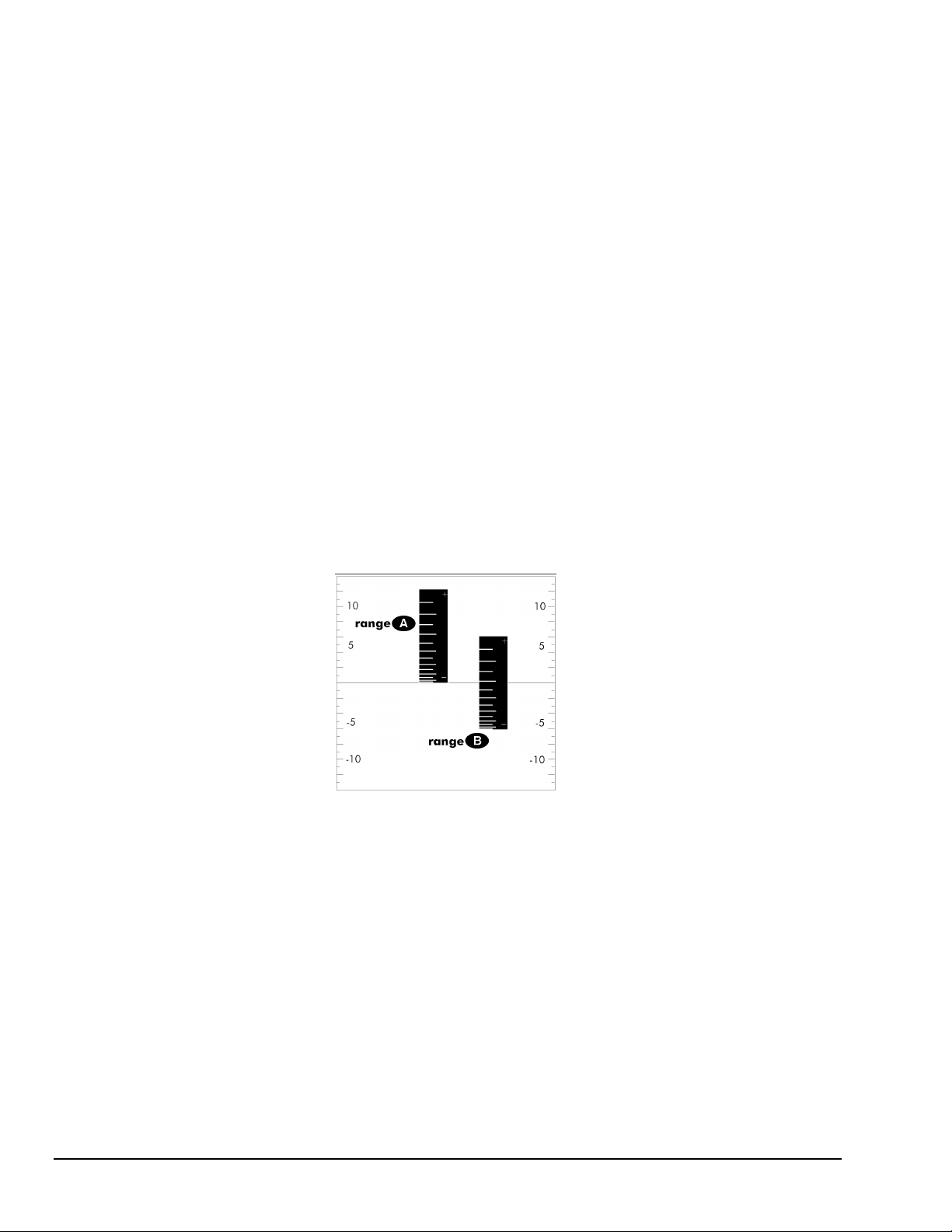
Dynamic resolution is always best toward the negative end of any range:
Dynamic Resolution for Dissimilar Ranges
Two vertical black “rulers” (range A and range B) portray the impact of Dynamic Resolution.
Their graduations – representing their ability to resolve – are always finer at the lower (more negative) ends
of their ranges, regardless of the spectrum of values the ranges are measuring.
1-2 Introduction & Installation of the Data Shuttle
11-13-01
DataShuttle and DynaRes
Page 11

Features and Configurations
Analog Input Channels DataShuttle-16 can achieve 16 bit resolution (.0015% of signal).
Resolution Selections
Data Acquisition Speed
Ranges
Noise Rejection
Sensors
Accuracy
Input Protection
Digital I/O
Counter/Timer
The DataShuttle-16 has eight differential analog input channels.
The resolution of the DataShuttle is selectable in software. With the
DataShuttle-16, it extends from 10 through 16 bits.
(These products also feature advanced “dynamic resolution.”
See page 1 – 2 for further explanation.)
The data acquisition rate for the DataShuttle reaches as high as 6 kHz at 9 bits,
in burst mode.
DataShuttle has six voltage ranges, all selectable individually for each analog
input channel.
The DataShuttle features a high noise rejection integrating converter
(in “low noise mode” it helps reject 50/60 Hz AC power line interference).
The DataShuttle supports accurate cold junction compensation and
linearization for thermocouple devices, and signal conditioning for resistance
temperature devices (RTDs).
Calibration constants are stored in non-volatile memory on each DataShuttle.
Built-in circuitry assures protection of analog input channels for ±50 Volts
continuous.
All DataShuttles feature eight digital input/output channels that the user can
configure individually to be input or output.
Every DataShuttle includes a counter/timer for precise timing (for counting
pulses or other events) which you can also use as a pulse output.
Counter/Timer controls analog pacing and is therefore, unavailable for use
with DASYLab software.
Isolation
Analog Output
Channels
The digital I/O lines on all models may be isolated with optional ODC
(opto 22) family modules.
The 5B models also accept optional –5B family isolation modules for analog
inputs and/or analog outputs.
All DataShuttle-AO models feature two optional 12-bit analog output channels
with one current (4-20mA) and six voltage ranges, software selectable
DataShuttle and DynaRes
11-13-01
Introduction & Installation of the DataShuttle 1-3
Page 12

For More Information
For more information about the capabilities of your DataShuttle, please see the “Product Specifications” in
Chapter 2.
For instructions on controlling the unit with our interface software (such as DASYLab or QuickLog), refer
to that particular software manual.
To learn more about data acquisition and process control in general, and how to use our systems together to
accomplish everyday tasks, consult our Applications manual.
If you’re creating your own program to address the unit for a custom purpose, please see the Analog
Connection Development System help section.
System Requirements
Before installing the DataShuttle, make sure the computer system fulfills these minimum requirements:
Hardware
•
IBM PC AT (or higher) or -compatible, with at least 640k system RAM,
•
Floppy disk drive, CD-ROM drive and a hard drive.
Software Environment
•
Windows 3.1/95/98/NT,
•
Application software (DASYLab, QuickLog PC, the Analog Connection Development System, or other
compatible proprietary software; please see your software manual for directions for using it with the
DataShuttle). QuickLog for Windows 3.1, 95/98 only.
Package Contents
Your DataShuttle package should include:
•
One DataShuttle
•
One 6V 1A AC Adapter; or 5VDC,~2.5A Adapter for
DS-5B models (for U.S. market; may differ for international markets)
(Polarity )
•
One parallel cable (DB-25 M-F) IEEE 1284 Compliant.
•
This manual, including DataShuttle, QuickLog PC, and Applications
•
One QuickLog for Windows Disk
•
One Quickstart card
DataShuttle Model Variations
The DataShuttle family line offers 4 basic models, plus versions with 2 optional analog outputs.
DataShuttle-GP
The DS-16-8-GP and DS-16-8-GP-AO are general purpose units designed for all types of inputs. The DSGP features terminals for 8 differential analog inputs and 8 digital I/O lines, with room for up to 8 highpower optically isolated models.
1-4 Introduction & Installation of the Data Shuttle
11-13-01
DataShuttle and DynaRes
Page 13
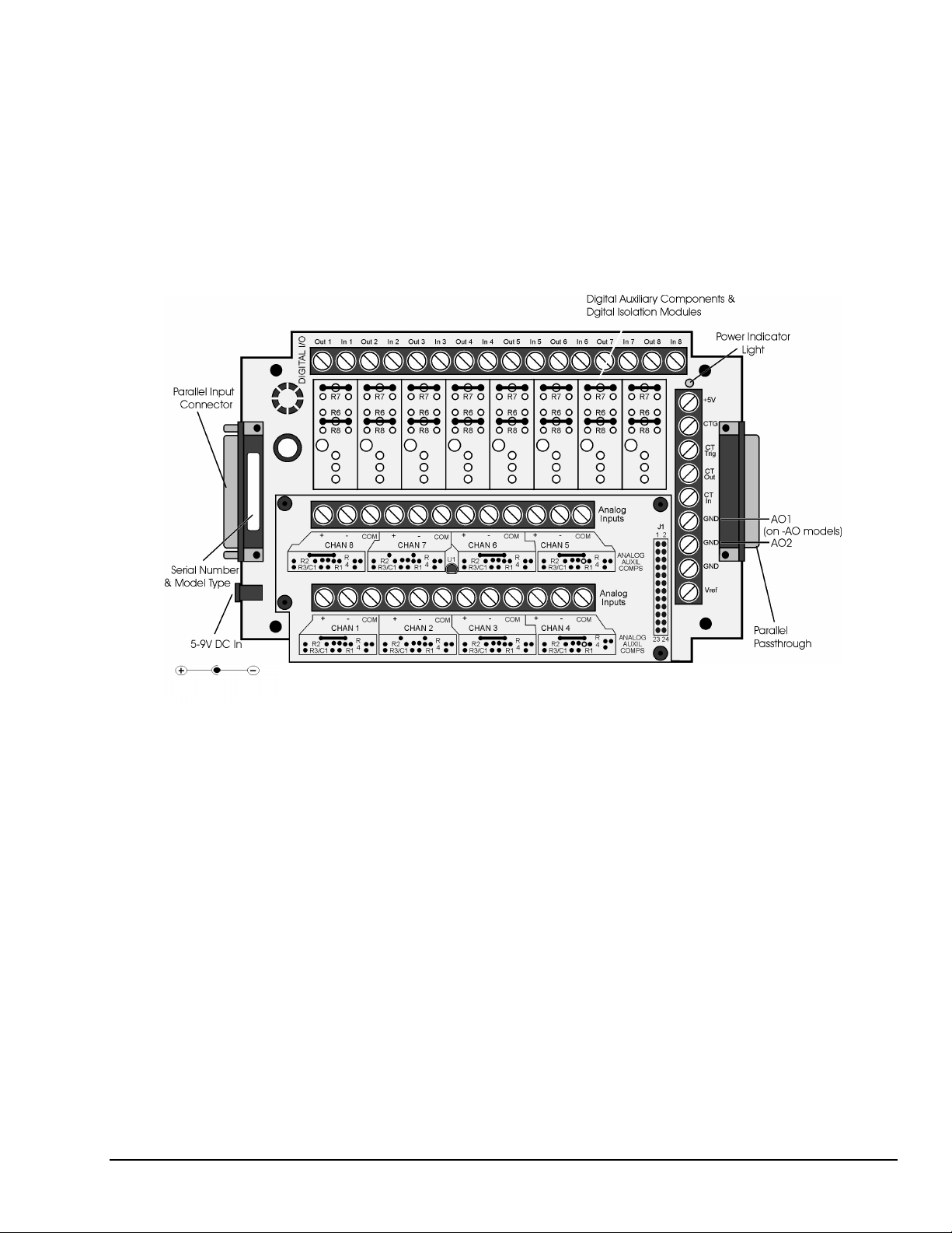
DataShuttle-RTD
The DataShuttle RTD models are specifically designed for high accuracy RTD measurements. The DS-168-RTD-115e version is suited for –200°C to 115°C measurements, and the DS-18-8-RTD-750C version is
suited for –200
factory for use with two or three wire RTDs. This model also features terminals for 8 digital I/O lines, with
room for up to 8 optically isolated modules. Two analog outputs are available on the –AO models: DS-168-RTD-115C-AO and DS-16-8-RTD-750C-AO.
The DataShuttle-RTD can also measure non-RTD inputs. For channels that are required to measure other
signals, remove the pre-installed resistors at R3 and R4. See example in the Analog Auxiliary Components
section of Chapter 2 for a more detailed illustration.
o
C to 750 °C measurements. Both have signal conditioning set resistors pre-installed at the
DataShuttle and DynaRes
Illustration of the DataShuttle-GP and DataShuttle-RTD
11-13-01
Introduction & Installation of the DataShuttle 1-5
Page 14

DataShuttle-TC
The DS-16-8-TC is the best model for thermocouple measurement. The DS-TC has a large aluminum
isothermal plate with screw terminals for 8 analog inputs. This isothermal plate improves accuracy by
attenuating temperature differences at the cold junction connector. Without this plate, the connectors can
vary in temperature by 5°C or more, causing a similar error in the reading reported by the DataShuttle .
The plate, however, does not prevent measurement of other signals, such as voltage or current. In addition,
the DataShuttle-TC features 8 digital I/O lines, with room for up to 8 optically isolated modules.
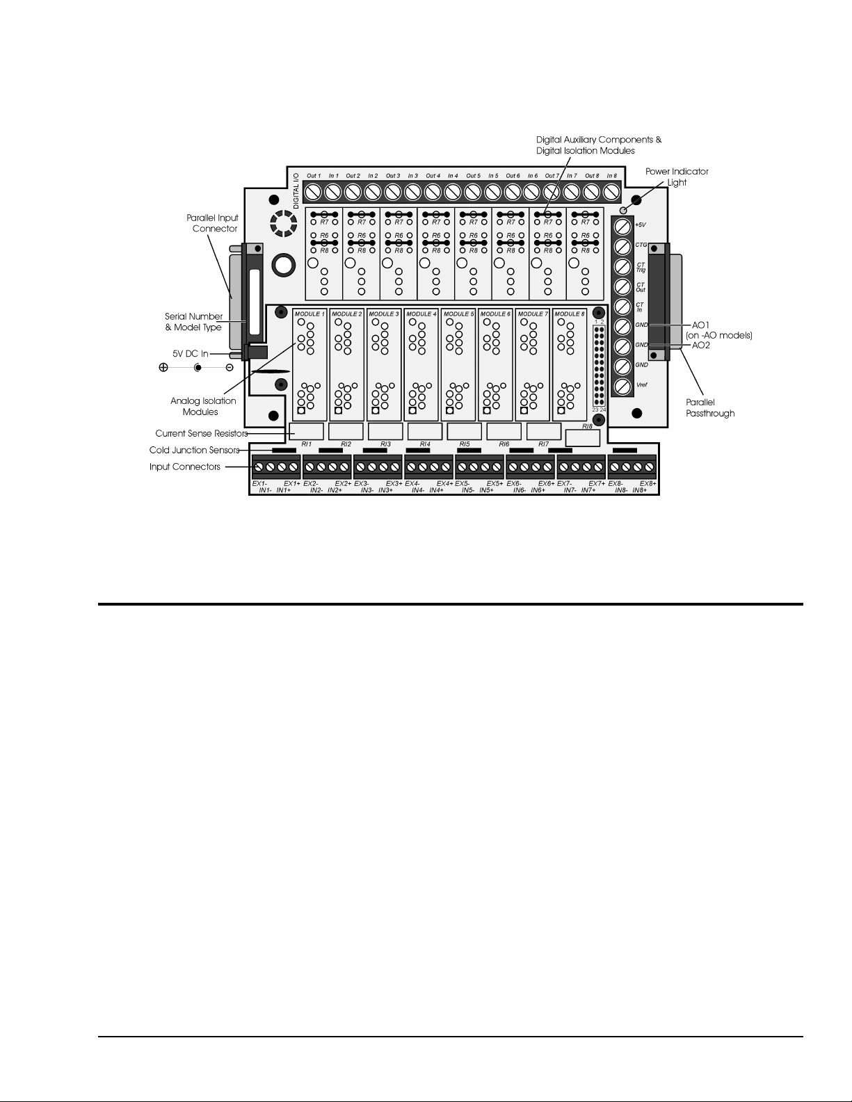
DataShuttle-5B
The DS-16-8-5B-AO offers the most compact solutions available for electrically isolating analog inputs,
analog outputs, and digital I/Os—all in one package. Up to 1500V isolation is available when installed with
the optional 5B modules for analog channels and/or opto22 modules for digital channels. The DS-5B’s
encasement is custom-designed to support the installation of these 5B modules.
The DS-5B features terminals for 8 differential analog inputs and 8 digital I/O lines; two analog outputs are
available on the –AO models. For maximum accuracy, each channel has a temperature sensor for
thermocouple cold junction compensation. Excitation terminals for driving strain gauges are also included
on each channel. In addition, each channel can accept current sense resistors for 4-20mA measurements.
Illustration of the DataShuttle-TC
1-6 Introduction & Installation of the Data Shuttle
11-13-01
DataShuttle and DynaRes
Page 15
Before installing 5B or opto22 isolation modules, it will be necessary to remove jumpers. Note also that if
two output isolation modules are installed, only six analog inputs are available for isolation. Odd-numbered
channels (1, 3, 5 or 7) should be used to track Analog Output 1 (AO1) and even-numbered channels for
Analog Output 2 (AO2).
Installing Your DataShuttle
Getting your DataShuttle up and running is a straightfoward process; you only need to:
•
Connect the DataShuttle to the parallel port of a computer, and
•
Connect power to the DataShuttle.
Guidelines for loading the software, and for starting up, depend on the application program you are going to
use (such as DASYLab
authorization).
The program you are going to use with the DataShuttle might even be unique and proprietary, a product of
your organization. (The Analog Connection Windows Development System is a powerful set of utilities
making it possible for software engineers to design and develop their own programs to exploit the
DataShuttle’s many features).
®
or QuickLog™, or a package by a third party developer who has our
Illustration of the DataShuttle-5B
DataShuttle and DynaRes
11-13-01
Introduction & Installation of the DataShuttle 1-7
Page 16
In any event, please refer to the software provider’s installation manual, or user guide, for specific
information on how to load and run the particular program.
Troubleshooting
section in Chapter 2.
Be sure to turn the power to the DataShuttle and computer off before making or
removing connections.
Always remove the AC adapter from the power line before disconnecting it from the
DataShuttle.
Physical Installation
Installation very simply consists of plugging the DataShuttle’s DB-25 cable into the parallel port outside
your computer. The DataShuttle may be used in combination with any of our data acquisition products.
To Install a DataShuttle
Single Unit Installation
1. TURN THE COMPUTER OFF. Never plug anything into the computer’s parallel port without first
turning its power switch to the “off” position.
2. Connect the parallel input connector, on the left side of the DataShuttle, to the parallel port on your
computer with the provided DB-25 cable. The parallel port on the PC has 25 pins and is often
labelled “Printer” or “LPT.” Computers may have up to four parallel ports; the DataShuttle may
be connected to any one of these.
–
If you have any difficulty getting your unit to work, refer to the “Troubleshooting”
:$51,1*
3. Connect the provided AC Adapter to the 6-9V DC input just to the side of the parallel port of the
DataShuttle. Plug the AC Adapter into an AC power line.
4. Connect the sensors needed for your application: Remove the top cover of the DataShuttle by
removing the four screws in the corners of the unit. Connect the sensors needed for your application
to the DataShuttle screw terminals. Replace the cover. You may wish to refer to the Applications
Reference Manual for examples of particular applications.
Multiple Unit Installation
To install more than one DataShuttle– Follow the steps above to install the first DataShuttle. Then for every
additional DataShuttle you wish to install, simply connect the parallel input port of that DataShuttle to the
passthrough port of the previously installed DataShuttle. You may use the additional DB-25 cables to do
this, or you can plug the next DataShuttle directly into the previous one. If you prefer to keep the units
separate, you may also connect additional DataShuttles directly to any or all of the other parallel ports on
your computer.
In any of these ways, you may connect up to 15 DataShuttles to one computer.
Please note, however, that only two DataShuttles, may be powered off the same 6V, 1 amp AC Adapter.
Therefore, you must connect a new AC Adapter (see Step 3 above) to every third DataShuttle in a series.
This number may vary outside the U.S.
&$87,21
The DS-16-8-5B models are shipped with a 5V DC, ~2.5A regulated adapter instead of
the standard 6V adapter. If you are using DS-16-8-5B model(s) in your installation,
note that each of those units will require its own adapter.
Polarity
1-8 Introduction & Installation of the Data Shuttle
11-13-01
DataShuttle and DynaRes
Page 17
A Note on Board Numbers– When you are using multiple units in your installation, each unit needs to have
an identity, or “board number,” for the software to recognize it as “individual.”
When the software is loaded, it will conduct a search for all installed hardware, scanning first for in-system
boards and then for any DataShuttles connected to the parallel ports. Any plug-in boards that you have
installed will be assigned a board number first. Then the DataShuttle connected at LPT1 nearest to the
computer will be assigned the next available board number. Additional DataShuttles on LPT1 will
be assigned sequentially higher board numbers following the connection order. This process will
be repeated on LPT2, LPT3, and LPT4 until all units have received a board number.
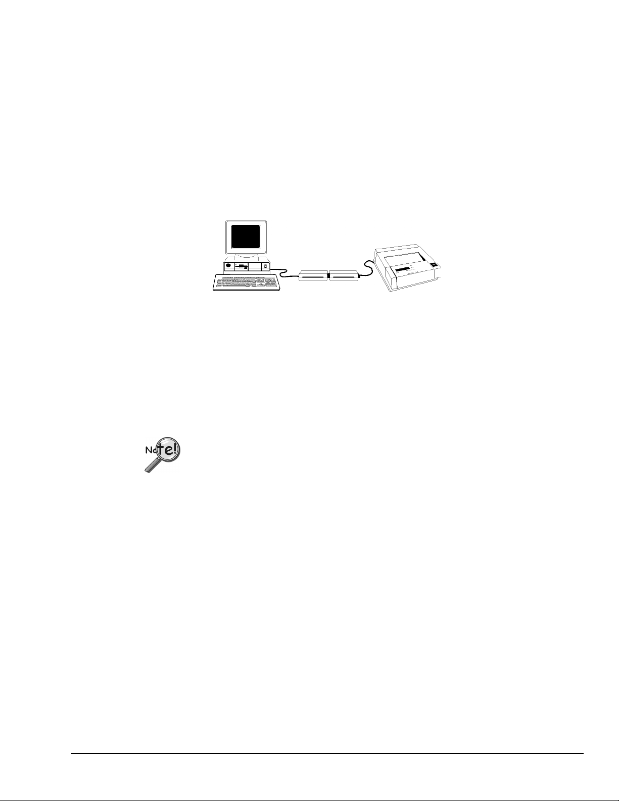
Printer Installation
If you wish to use a printer on the same parallel port as a DataShuttle– Connect the printer cable to the
passthrough port of the last DataShuttle in the series. Printing can only take place when the DataShuttle
is powered and the data shuttle is not collecting data.
Figure 4. Installation with multiple DataShuttles and printer
Keyboard Adapter Installation
For field applications where no AC power line is available– The Keyboard Adapter power cable (available
optionally) may be used instead of the AC Adapter. To install, simply connect one end of the cable to the
keyboard port on the computer. (This connector must be the six-pin mini DIN style found on IBM PS-2s
and most portable computers.) Plug the other end of the cable into the DataShuttle’s DC input jack.
Next Steps
We recommend that only one DataShuttle be powered off a keyboard adapter; this may vary depending on
the computer used. (See the “Multiple Unit Installation” section for instructions on installing multiple
DataShuttles.)
If you are using DS-5B model(s) in your installation, it is recommended that you use an
external power source. The keyboard adapter might not meet the power requirements of
some DS-5B experiment setups.
Installing the Software – For information on loading and configuring DASYLab, QuickLog PC, or other
software please refer to the user guide for that software package.
DataShuttle and DynaRes
11-13-01
Introduction & Installation of the DataShuttle 1-9
Page 18

1-10 Introduction & Installation of the Data Shuttle
11-13-01
DataShuttle and DynaRes
Page 19
DataShuttle - Technical Notes 2
Although the technical notes presented in the following pages should seldom be needed, you may find one
or more of them to be of use, on occasion. The technical notes are:
•
Block diagram (of the DataShuttle showing on-unit processing)
•
Editing calibration numbers to accommodate changes to your installation,
or to restore missing files
•
Auxiliary analog and digital components
•
Counter/Timer
•
Use with AC Development System software
•
Troubleshooting: possible problems and solutions after installing,
and during operation of your unit
•
DataShuttle Specifications
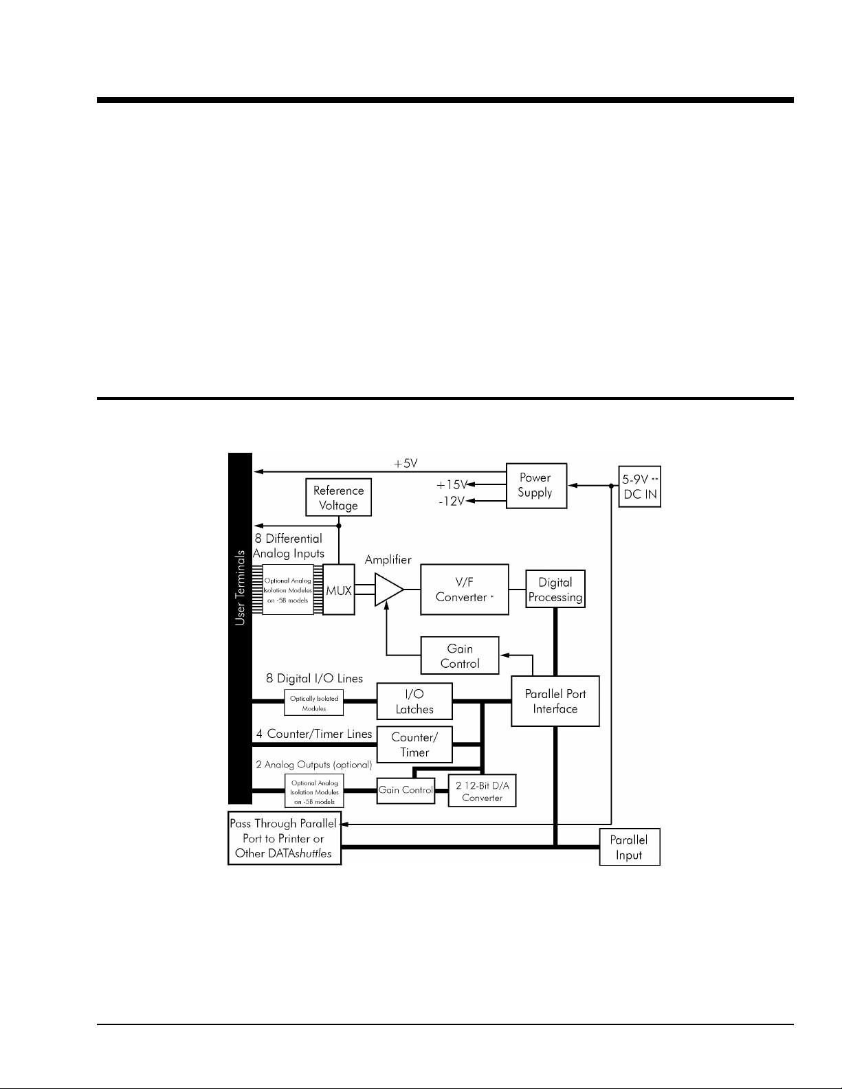
Block Diagram
DataShuttle and DynaRes
Block Diagram of DataShuttle-16
11-13-01
*V/F Converter: 16 bits
**5V DC in for DS-5B models
DataShuttle - Technical Notes 2-1
Page 20

EDITCAL
DataShuttles are calibrated at the factory prior to shipment, and should not need
re-calibration when you receive your order. The recommended calibration period is 2
years. Note that changing calibration numbers affects the accuracy of the analog
measurements.
EDITCAL.EXE (or EDITCAL, for short) is our utility program that allows the modification of calibration
numbers. Steps for starting and using EDITCAL follow.
1. Make sure the EDITCAL.EXE program file is located in the same sub-directory as the
application programs.
2. Load the EDITCAL.EXE program from the keyboard.
3. At the DOS prompt, enter EDITCAL, then press the [ENTER] key.
This invokes the utility.
Once EDITCAL is up and running you can use the arrow keys to navigate back and forth
among the following menu selections:
Data Files: To merge calibration files supplied from the factory into a single file for
systems that have multiple units, or to update existing calibration files.
AC EEPROM: To view or modify calibration data on Analog Connection units that
have non-volatile on-unit EEPROMS.
DS EEPROM: To view and/or modify the calibration numbers of DataShuttle
EEPROMs, or to perform an analog calibration
QUIT: Ends the EDITCAL session.
4. Move the arrow keys until DS EEPROM is flashing.
5. Press [ENTER].
6. Proceed according to the on-screen instructions that appear after making your selection.
At any time during your use of EDITCAL, you can press the [F1] key to display helptext regarding a highlighted field.
2-2 DataShuttle - Technical Notes
11-13-01
DataShuttle and DynaRes
Page 21
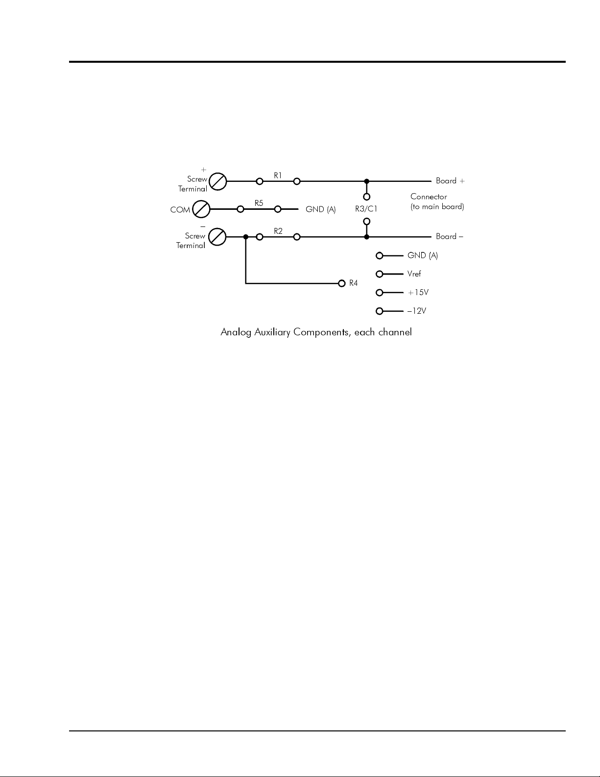
Auxiliary Components
Starting EDITCAL
Auxiliary Components are required by some sensors, are used to protect digital signals, or are used to pull
digital outputs to a set level. There are two areas (one digital and one analog) on the DataShuttle for
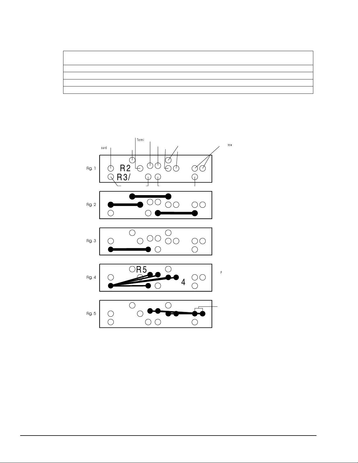
installing auxiliary components. Schematics of Analog auxiliary components are shown in detail on
page 2-3. Schematics of Digital auxiliary components are shown in detail on page 2-6.
Schematic for Analog Auxiliary Components
Each channel on the DataShuttle has room for its own separate set of auxiliary components. Examples of
their use can be found in the following pages and in the Applications Reference Section.
Analog Components
Instructions for Installing Components
Most common sensors can be connected without the use of auxiliary components. Some of the sensor
installations (bridges, RTD circuits, voltage dividers and current sensors), however, require auxiliary
components. These components can be installed on the DataShuttle for convenience. This requires soldering
and some familiarity with electronics. In the examples in the Applications Reference Manual, and the
following, the component locations are shown but not the component values; you must calculate the values
if they are not supplied with the sensor.
The first step is to remove the daughterboard from the unit, as you will need full access to it for soldering on
the auxiliary components. To do this, simply remove the four screws in the corners of the daughterboard
and lift it off of the DataShuttle.
When using analog auxiliary components R1, R2, and R5 you must cut the shorting metal trace that
connects the two ends of the line together before installing any of the components in these locations. Use a
sharp knife to carefully slice through the trace without cutting additional traces. In the case of R5 this is a
plastic covered metal wire. Diagrams of the auxiliary component area, hole functions, and connection
possibilities are shown on the following page.
Note: Analog auxiliary components are not available on DS-5B models.
DataShuttle and DynaRes
11-13-01
DataShuttle - Technical Notes 2-3
Page 22
Power Supplies
A Note on Power Supplies – The DataShuttle supplies the following voltages to power transducers, strain
gauges, etc. The currents available to the user are limited as follows:
Voltage Tolerance
Maximum Current
(mA)
Output Impedance
(ohms)
Vref(6.9V) ±5% 10 <1
+5V 4.5 to 5.0V 100 <50
+15V ±3% 10 100
-12V ±3% 10 100
Users of the open collector digital outputs and buffer amplifiers should be careful not to exceed these limits.
Any power used from these supplies will add to the specified supply current used by the DataShuttle.
−
Screw
Ter m inal
)LJ
)LJ
Board
−
GND (A)
R5
R2
R3/C1 R1
Board + Board
R5
R2
R3/C1 R1
−
Ground (A)
Vref
Board +
+15V
COM
−
12V
R
4
R
4
+ Sc rew Term ina l
Screw
−
Terminal
Placement of holes
in auxiliary component
area for a single channel
Placement of resistors
R1, R2 and R5.
)LJ
)LJ
)LJ
R5
R2
R3/C1 R1
R5
R2
R3/C1 R1
R5
R2
R3/C1 R1
R
4
R
4
R
4
Placement of capacitor
C1 o r R3 R es istor fo r
current measurement.
Placement of R3 may
be to one of five places
on the right side of the
resistor.
R4 may be in one of
two holes on the right
side to one of 4 holes
on the left.
*Except DS-5B models
Analog Auxiliary Component Area on the DataShuttle
2-4 DataShuttle - Technical Notes
11-13-01
DataShuttle and DynaRes
Page 23
Examples
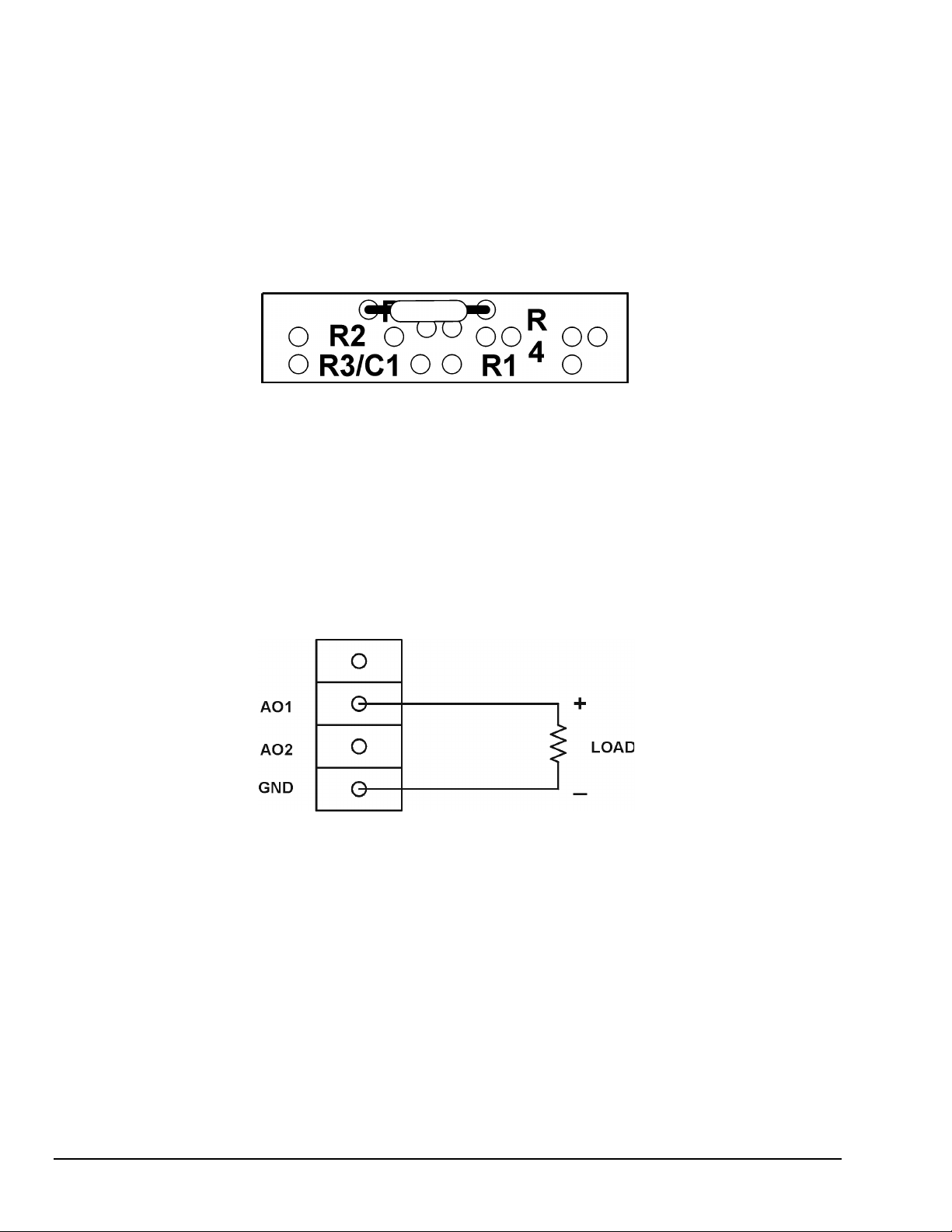
Example 1: Current Sense Resistor
The DataShuttle can measure currents up to 50 mA directly. A 24.9 Ohm precision resistor needs to
be installed in the auxiliary component area to do so. This connection for current measurement is shown
below. (To see how this connection adds to the circuit, refer to Figure on page 2-3.) R3 is used as a shunt
resistor across the positive and negative lines of the channel in use. To install this resistor, push the resistor
ends through the holes for R3 (from the terminal side) until the resistor lies flat with the panel surface.
On the backside, solder the wires to the holes, and then clip off the extra wire with pliers. This connection
does not require any additional traces to be cut. Be sure to select current measurement in the software
package that you are using. This installation allows the measurement of voltage across the resistor and the
conversion of this measurement to current using the equation V=IR. Observe the power rating of the resistor
you install at R3. Space is provided for a 1/4 Watt resistor.
Figure 6. Current Measurement Connection
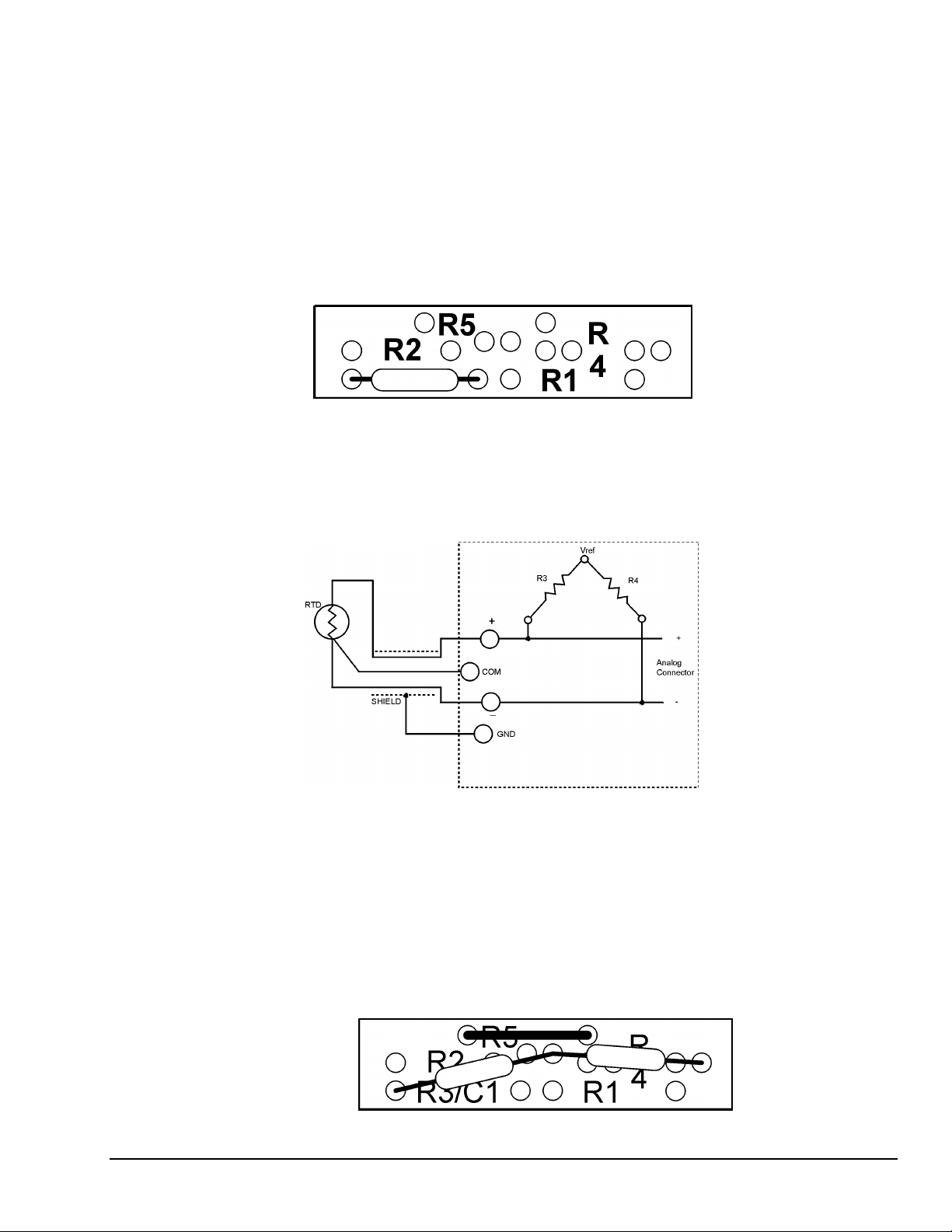
Example 2: 3-Wire RTD Components
The most popular connection for RTDs is the three-wire type. This sensor requires the installation of
resistors R3 and R4 except for these DataShuttle RTD model, where both resistors are already installed.
Consult Set Resistor Values on page 2-14 for R3 and R4 values.
However, if you need to install these resistors yourself then do the following: Figure 4 and Figure 5 show
the possible locations of R3 and R4. Figure 1 will show you that R3 and R4 need to be connected
as in Figure 14. R5 is already in place and should not be removed. To install these resistors push the
resistor ends through the holes for R3 and R4 as shown in Figure 4 (from the terminal side) until the resistor
lies flat with the panel surface. If two wires cannot fit into the Vref hole then one wire may be soldered
to another that is already inserted. On the back side solder the wires to the holes. Then clip off the extra
wire with pliers. The auxiliary component area in question will now look like Figure 8. This connection
does not require any additional traces to be cut.
DataShuttle and DynaRes
.
3- Wire RTD
Figure 7. 3-Wire RTD Components
Figure 8 . 3-Wire RTD Connection
11-13-01
DataShuttle - Technical Notes 2-5
Page 24
Example 3: Ground loops
Occasionally there is an installation where the ground connection is made at the sensor, but it is not reliable.
The solution to this “intermittent” ground is to replace the COM to GND(A) jumper wire at R5
(Figure on page 2-3) with a 10 Megohm, 5%, 1/4 Watt resistor. This provides a ground reference for the
analog inputs in question, but allows very little ground current to flow. In very noisy environments with
intermittent grounds, a smaller resistor may be used if the readings are erratic.
To install this resistor the wire at R5 must first be removed. After R5 has been removed push the resistor
ends through the holes for R5 (from the terminal side) until the resistor lies flat with the panel surface.
On the backside, solder the wires to the holes. Then clip off the extra wire with pliers. The auxiliary
component area in question will now look like Figure 9. This connection does not require any additional
traces to be cut.
Figure 9. Ground Loop Connection
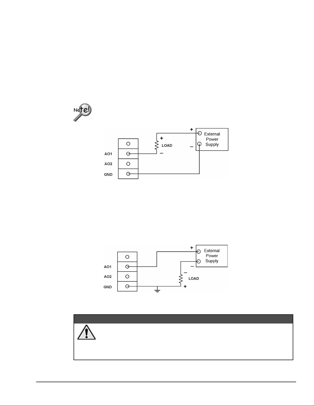
Wiring Analog Outputs on the DataShuttle
Voltage Outputs
Voltage outputs can drive a wide variety of controllers, amplifiers, and other devices. Figure 9a shows the
standard way in which the Data Shuttle analog output terminals are connected to a load when the “Voltage
Output” option has been selected in the software.
Note: The load resistance should be at least 1000 ohms to guarantee that the output will not have to source
more than 10 mA.
Figure 9a. Voltage Output
2-6 DataShuttle - Technical Notes
11-13-01
DataShuttle and DynaRes
Page 25
Current Outputs
Most current outputs connect to current loop devices, such as controllers. If you select the
“Current Output” option in the software then, the output current loop will be in the 4 to 20 mA range.
A 4 to 20 mA current device has the advantage of running the power and signal over the same pair of wires.
Also, current signals are much less susceptible to noise pickup than are voltage signals.
Note: The current loop connection on the Data Shuttle must be powered by a + 12V source. Since no such
source is available on the Data Shuttle itself, an external power supply must be used
Ungrounded Load
Several loads can be powered from a single supply, as long as the negative side of the supply is connected
to the Data Shuttle ground. The circuit in Figure 9b is the most common way to connect a current loop to
the Data Shuttle. In this case, the load is not grounded but is floating above ground level.
If there are multiple loads, then the negative terminal of each load must be connected to a
separate Analog Output (AO) terminal on the DataShuttle.
Figure 9b. Current Output, Ungrounded Load
For the current output option to work properly, the voltage from each AO terminal to ground must be at
least 2.6 volts. Therefore, since the voltage source may vary by +/- 1 V, the maximum load resistance that
can be used in this circuit is 420 ohms.
Grounded Load
If one side of the load must be grounded for some reason, use the circuit shown in Figure 9c. The
disadvantage of this circuit is that each load requires its own power supply. The same maximum load
resistance applies, i.e., 420 ohms.
Figure 9c. Current Output, Grounded Load
&$87,21
Inadvertent damage to the Data Shuttle’s Analog Output is possible! Some
situations can occur in which the software could start up in a default voltage
mode [instead of the selected current mode]. To avoid this possibility,
physically disconnect the current loops from the Data Shuttle prior to
shutting down or disabling the software, or prior to rebooting the PC.
DataShuttle and DynaRes
11-13-01
DataShuttle - Technical Notes 2-7
Page 26
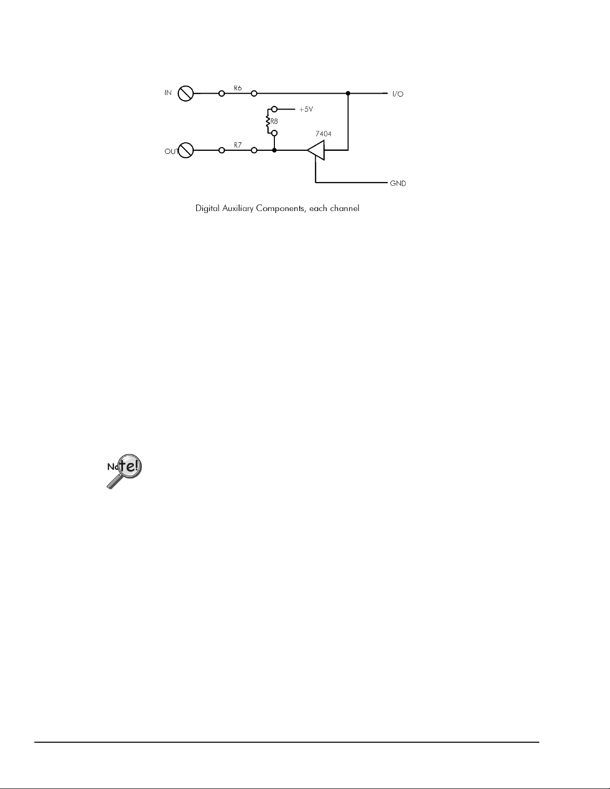
Digital Components
Installing Digital Modules
Opto22 modules are available to safely connect the digital I/O lines to high voltage AC and DC sources.
There are four basic types:
Schematic for Digital Auxiliary Components
•
AC output: to switch AC power (relay)
•
DC output: to switch DC power (relay)
•
AC input: to sense AC voltage
•
DC input: to sense DC voltage
The output types are used to switch loads on and off. The input types are used to sense the high/low status
of a signal. All of the modules provide optical isolation between the high voltage and terminations.
These modules may be installed on any DataShuttle. First, remove the jumpers labeled R6 and R7. This
disconnects the digital I/Os from the terminals. The module will not fit into the panel until these jumpers are
removed. Then, simply insert the module and fasten the retention screw.
The terminals for that I/O have now changed their function from low voltage I/O to high voltage isolated
I/O. The two terminals become one input channel (high and low lines), or one output channel (like relay
contacts), depending on the type of module you have installed.
When using these terminals as input lines, be sure to connect the positive line to the old
OUT terminal and the negative line to the old IN terminal. Failure to do this will result in
the module not switching.
Installing Pull-up Resistors
As noted in the Applications Reference Manual and previously in this manual, the digital outputs are open
collector and must have a power source connected in order to drive loads. Merely connecting the output
terminal through a load (such as a bulb) and then to digital ground will not work. In this case, a pull-up
resistor connecting the output terminal to a power supply will complete the circuit.
This pull-up resistor is installed in position R8, as shown in the figure on page 2-6, which connects the
output to the unit’s +5 volt power supply. Figures in Chapter 1 show the physical location of R8 on the
DataShuttle. Note that R8 must be installed manually between the +5 volt supply and the output terminal
in question. To install this resistor, push the resistor ends through the holes for R8 (from the terminal side)
until the resistor lies flat with the panel surface. On the backside, solder the wires to the holes. Clip off the
extra wire with pliers. This connection does not require any additional traces to be cut. Use a 4.7K resistor
to give 1mA current flow or a 2.3K resistor to give 2mA current flow.
2-8 DataShuttle - Technical Notes
11-13-01
DataShuttle and DynaRes
Page 27

Installing Current Limiting Resistors
To limit the current in the digital input line, install a resistor in the R6 position (remove the corresponding
jumper first).
Install a resistor in the R7 position (after removing the jumper) to limit the current in the digital output line.
Counter/Timer
The DataShuttle features one 16 bit counter/timer that may be used to count up to 216 (65,535) events. The
maximum rate of pulses it can measure is 3MHz. The counter/timer is connected to an internal 2MHz clock,
allowing it 0.5µS resolution.
There are four dedicated terminals for the counter/timer:
Counter/Timers lines available on the DataShuttle
Label Name Function
CTG Gate Input/output functions may operate when this line is high and stop
CT Trig Trigger Initiate input or output functions on rising edge
CT Out Output Output pulses or square waves
CT In Input Measure frequency of pulses, count pulses, or time events
All of these lines are TTL compatible. Please note that they may not be optically isolated with modules.
For more information and examples about the uses of the counter/timer please see the Applications
Reference or QuickLog chapters.
when it is low
Troubleshooting: Installation
If you experience difficulty in getting your DataShuttle up and running, please check to see that the
installation is according to the descriptions in Chapter 1.
If the software reports a unit failure, or that it cannot find a DataShuttle, then try these remedies:
1. Make sure the cable is securely connected from the DataShuttle input connector to the parallel port
on the computer.
2. Make sure the DataShuttle is connected to a power source, either an AC Adapter or Keyboard
Adapter. A red light on the board will indicate that power is present.
3. Verify that the software is up to date (a version compatible with the unit you are using). Contact us,
or your software provider.
DataShuttle and DynaRes
11-13-01
DataShuttle - Technical Notes 2-9
Page 28

4. Disconnect additional DataShuttles and printers in your setup.
5. Connect the DataShuttle to another parallel port.
6. Remove any additional data acquisition cards from the computer.
7. If possible, install the DataShuttle with another computer to verify its correct operation.
8. Remove other terminate and stay resident (TSR) programs from your system’s AUTOEXEC.BAT
file, temporarily. Also REM out any AUTOEXEC.BAT and CONFIG.SYS lines that relate to a
PCMCIA port, such as device drivers, as these have been known to cause conflicts.
9. Make sure that you plug the DataShuttle in and that power is connected before starting your
computer. Many laptops will deactivate the parallel port at the start-up if nothing is attached to it.
10. Make sure that the Print Manager is not active in the Windows environment when attempting to start
the DataShuttle. Some computers automatically load the Print Manager at startup, and it can interfere
with DASYLab’s ability to communicate with the hardware. Printing is possible while using the
DataShuttle but not during the initial loading of the DASYLab software. Likewise check for lack of
interrupt assignment on parallel port in device manager.
11. Erratic behavior can occur when a parallel port is in ECP modes under early Windows 95 versions.
Change parallel port protocol in BIOS.
12. QuickLog checks for [386Enh]
DEVICE=C:\QLFW\STIDATAQ.386
in System.ini file
13. Increase Minimum Interrupt Timing setting. (consult software manual)
If You Need Customer Support
To help us serve you better, please have the following information ready:
1. Have the part number of your DataShuttle ready.
2. Have the type and version number of the software you’re using.
3. Have your computer’s type, model, and the version of the operating system.
2-10 DataShuttle - Technical Notes
11-13-01
DataShuttle and DynaRes
Page 29

Troubleshooting: Operation
Hints
It’s essential to have exactly one ground reference per channel. This single connection to ground makes sure
you don’t exceed the common mode range of input.
(More than one connection per channel can lead to ground loops, causing errors or erratic readings.
Connecting the – to the Com terminal provides a single ground. Your sensor might also provide another
ground. If you’re not sure that your sensor is grounded, try connecting the – to Com, and not, and see which
works best.)
Remember that if speed is not critical, selecting the “low noise mode” in software always provides the best
accuracy and resolution with your data acquisition unit.
Operating Qs and As
1. Problem: My unit reads analog inputs wrong.
Action: Make sure the calibration numbers in the non-volatile memory are non-zero
(run EDITCAL to check this). If the figures are correct, try shorting + to – to Com: the unit should
return a reading around 0V.
2. Problem: My unit reads the thermocouple as a very negative temperature.
Action: Verify the connections are secure. Opens read as negative temperature. Make sure use
lowest channel numbers first and scan only connected channels.
3. Problem: My board reads thermocouple input wrong.
Action: Confirm that the CCAL number in the EEPROM matches the number on the terminal panel’s
calibration label.
(If you need to use a general purpose terminal panel – one that doesn’t have a factory CCAL
number – with a thermocouple, you can achieve approximate results by entering a CCAL of 22000.
Then change the figure by about 75 points for each degree C. that you want to raise the temperature.)
4. Problem: My readings are noisy.
Action: Try using the low noise mode (see your software manual for more information).
5. Problem: My digital inputs are “high” with nothing connected to them.
Action: This is normal. The digital inputs are pulled up to about 1.5 volts by leakage from the
LS7407 chips. This is enough to read logic high. You can pull them low with a 470 ohm resistor to
ground.
6. Problem: Can I get any output signal from the digital input terminals?
Action: Yes, you can use an input terminal to drive light loads such as a TTL input.
7. Problem: What should I do with the jumpers connecting the analog input to COM?
Action: In general, it is best to leave them connected as shipped.
8. Problem: My 5V terminal reads only 4.6V.
Action: This is normal. Tolerance is 4.5 to 5V.
9. Problem: There is significant crosstalk
Action: High impedence, greater than 1K, inputs, such as accelerometers require signal conditioning.
10. Problem: My analog output accuracy is poor.
Action: From the DOS command line, or in GO.BAT, run GFIND -C. This calibrates analog outputs.
Note, however, that calibration sends full scale outputs, so it may be necessary to remove any
instruments connected to the outputs.
11. Problem: Errors in Thermocouples on multiple units.
DataShuttle and DynaRes
Action: If thermocouples are connected to metal, object, remove − to common strap on terminals.
11-13-01
DataShuttle - Technical Notes 2-11
Page 30

Before Calling Customer Support
Check the following key areas to validate whether or not the DataShuttle is operational:
1.
Make sure the AC Adapter is not damaged. To do this, detach the adapter from the DataShuttle,
while leaving it plugged in to the wall outlet. Then measure the voltage between the inside and
outside surfaces of the cylindrical connector. In this no-load condition, the voltage should measure
approximately 9V. If this is not the case, it is likely that the AC Adapter will need to be replaced.
(Polarity )
2.
Check the power section of the DataShuttle. After plugging the AC Adapter back into the
DataShuttle, check to make sure the LED is functioning. If the LED is not lighting up, then there is
likely a problem with the power section of the unit. Contact technical support for further
assistance.
3.
Check the DataShuttle’s internal power supply. To do this, it is necessary to measure four voltage
terminals on the unit itself: the +5V and Vref(6.9V) terminals, found at opposite ends of the
terminal strip next to the passthrough connector, and the +15V and the -12V terminals, which can
be found on the raised section of the DataShuttle called the terminal board. (Please consult the
diagrams on pages 1–5 through 1–7 if you are unable to locate these terminals.)
If you have been installing resistors or capacitors on the analog input auxiliary section,
then it is necessary to remove the terminal board and re-check the +5V and Vref voltages. If, after
removal, these voltages return to normal, it is likely that there is a short-to-ground on the terminal
board. Check the resistor/capacitor installations for such a short and reinstall the board.
If removal does not fix the +5 and -12 voltages, then there is a problem with the DataShuttle’s
internal power supply. Contact technical support for further assistance.
If You Need Customer Support
To help us serve you better, please have the following information ready:
1.
Have the part number of your DataShuttle ready.
2.
Have the type and version number of the software you’re using.
3.
Have your computer’s type, model, and the version of the operating system.
2-12 DataShuttle - Technical Notes
11-13-01
DataShuttle and DynaRes
Page 31
Product Specifications
Accuracy DataShuttle-16 Accuracy & Resolution-
Typical Resolution
Range
-5 to +50 mV .8µV 0.04% -
-25 to +25 mV .8µ V 0.08% -
-50 to +500 mV 8µV 0.01% 0.05%
-250 to +250 mV 8µV 0.01% 0.05%
VOLTAGE
General Conditions – From 15 to 35 degrees C, ambient at the interface unit, source resistance less than
1k Ohms. Includes linearity, drift, offset, resolution, and calibration error.
If you are using a DataShuttle-5B, be sure to add the uncertainty of the isolation modules being used
to these specifications.
DataShuttle- 16 Thermocouple Accuracy
-1 to +10 mV 150µV 0.01% 0.05%
-5 to +5 mV 150µV 0.01% 0.10%
Type Range (°C.) Resolution (°C.) Accuracy (°C.)
J
K
E
T
S
R
B
G
D
C
N
-210 to –100 0.1 – 0.3 ± 2.3
-100 to 0 0.05 ± 1.2
0 to 880 0.05 – 0.2 ± 1
-250 to –75 0.15 – 1.0 ± 8
-75 to 1260 0.07 – 0.3 ± 1.4
0 to 900 0.06 – 0.2 ± 1.2
-250 to –70 0.1 – 0.5 ± 4
-70 to 100 0.04 ± 1
100 to 680 0.04 – 0.15 ± 0.8
-250 to –50 0.15 – 0.8 ± 6
-50 to 10 0.02 – 0.8 ± 1.4
10 to 150 0.06 ± 1.2
150 to 400 0.06 – 0.1 ± 1
-50 to 120 0.4 ± 10
120 to 380 0.3 ± 5
380 to 1770 0.2 – 0.6 ± 4
-50 to 250 0.2 – 0.4 ± 10
250 to 800 0.2 ± 4
800 to 1770 0.2 – 0.4 ± 3
200 to 300 0.7 – 1± 20
300 to 500 0.4 – 0.7 ± 13
500 to 1000 0.2 – 0.4 ± 8
1000 to 1820 0.2 – 0.4 ± 4
25 to 200 0.2 – 1± 15
200 to 2315 0.15 – 0.8 ± 4
-20 to 2315 0.2 – 1± 4
150 to 2000 0.15 – 0.6 ± 3
-20 to 2315 0.15 – 1± 4
100 to 1500 0.15 – 0.4 ± 3
-200 to –100 0.7 – 1.4 ± 5
-100 to 1300 0.4 – 0.7 ± 3
at Full Scale
Absolute Accuracy, the larger of
% of Range: % of Reading:
DataShuttle and DynaRes
11-13-01
DataShuttle - Technical Notes 2-13
Page 32

Thermocouple Conditions – Same as General Conditions. Does not include the accuracy of the
thermocouple itself (cold junction error must be added in; cold junction compensation with
DataShuttle-TCs only). Resolution assumes 12 bit resolution in use for DataShuttle-12, 16 bit resolution for
DataShuttle-16; it is approximate as resolution varies with temperature measured.
Thermocouples use the 50 mV range. For inputs below -5 mV (below approximately -100 degrees C),
use the +/-25 mV range.
Cold Junction Compensation Error – For the best resolution while using the DataShuttle-TCs, use the
50 mV range above -5 mV. Cold Junction Compensation Error (degrees C) at terminal temperature of:
Cold Junction Compensation Error
Type 25oC15
J
K
E
T
S
R
B
G
C
D
N
0 < 0.25 < 0.6
0 < 0.3 < 0.7
0 < 0.3 < 0.8
0 < 0.4 < 1.2
0 < 0.6 < 1.3
0 < 0.4 < 1.6
0 < 1.0 < 2.0
0 < 0.7 < 1.7
0 < 0.5 < 1.2
0 < 0.6 < 1.8
0 < 0.6 < 1.2
Cold junction compensation error is in reference to the temperature of the terminals. For types B and G the
above error applies for measured temperatures above 200 degrees C only. The cold junction sensor can
be re-calibrated at any temperature from 0°C to 50°C to improve the accuracy if it will not be used at 25°C.
Cold Junction Temperature Differential
For the DataShuttle-TC only, the temperature gradient in the air adjacent to the cold junction plate
is attenuated 15 times when AWG #22 gage or smaller thermocouple wire is used. The wires are bundled
together for at least one foot from the cold junction terminals. The error is usually less than 0.1 degree C.
For the DataShuttle-GPs there is no isothermal plate. The cold junction compensation error consists of the
above table plus the difference between the terminal temperature and the cold junction sensor.
This difference can be several degrees. The above table applies only after user calibration of the cold
junction.
o
& 35oC5
o
& 45oC
DataShuttle-16 RTD Accuracy
Set Resistor
Ω
10 k 50 -200 to 115 0.005 0.8
20 k 50 -200 to 525 0.01 0.9
20 k 100 -200 to 115 0.005 0.8
50 k 50 -200 to >850 0.03 1.4
50 k 100 -200 to 750 0.01 1.0
50 k 200 -200 to 115 0.005 0.8
100 k 100 -200 to >850 0.03 1.4
100 k 200 -200 to 750 0.01 1.0
100 k 500 -200 to 115 0.005 0.8
200 k 200 -200 to >850 0.03 1.4
200 k 500 -200 to 525 0.01 0.9
200 k 1000 -200 to 115 0.005 0.8
500 k 500 -200 to >850 0.03 1.4
500 k 1000 -200 to 750 0.01 1.0
1000 k 1000 -200 to >850 0.03 1.4
2-14 DataShuttle - Technical Notes
RTD
Range
Ω
°C
11-13-01
Resolution
°C
Accuracy
°C
DataShuttle and DynaRes
Page 33

RTD Conditions – Same as General Conditions. Does not include the accuracy of the RTD sensor itself.
Includes linearization and signal conditioning errors.
Assumes 16-bit resolution is in use for the DataShuttle-16.
RTD measurements are on the 0-50 mV range.
Input Impedance
All analog inputs have an impedance rating of >20M
Noise Rejection
Important: All noise measurements are in low noise mode, with inputs shorted to COM.
CMRR – Common Mode Rejection Ratio (CMRR) is >80dB under these conditions: DC to 100 Hz,
common mode input ± 7.0 Volts channel to ground. This specification applies even when one or more
nonmeasured channels exceeds the operating common mode range.
DataShuttle Noise Rejection
Range Typical Internal Noise (RMS)
50 mV 0.5 µV
± 25 mV 0.5 µV
500 mV 4 µV
± 250 mV 4 µV
10 V 50 µV
± 5 V 50 µV
Ω
Common Mode Range
Operating, channel-to-ground – ±7 Volts
Nonoperating – ±50 Volts continuous.
Input Protection
On analog input channels: 50 Volts continuous; 150 Volts momentary.
Resolution/Scan Rate
Both resolution and scan rate are selectable in software
DataShuttle-16 Resolution And Scan Rate*
Resolution Scan Rate
low noise mode: 0.0015 % 45 / 55 Hz
16 bits: 0.0015 % 200 Hz
15 bits: 0.003 % 330 Hz
14 bits: 0.006 % 500 Hz
13 bits: 0.0012 % 700 Hz
12 bits: 0.024 % 900 Hz
10 bits: 0.1 % 1400 Hz
* Rates describe an IBM PC 486DX2 running at 66 MHz under Windows 3.1;
tolerate error = 1 in DASYLab. Rates are somewhat faster in faster computers.
Also see the discussion of “Dynamic Resolution,” on page 1-2.
DataShuttle and DynaRes
11-13-01
DataShuttle - Technical Notes 2-15
Page 34

Analog Input
Scan Rate – Scan rate is the rate in Hertz (or, samples per second) to read data into memory, including the
time it takes to switch channels and ranges. To calculate the total scan time for all channels, divide the rate
by the number of channels.
For the Analog Input Terminals on the DataShuttle
•
Maximum voltage on any terminal: 150 volts.
•
Maximum voltage on DS-5B models: 1500 volts.
•
Maximum current on any terminal: 1 Amp.
Digital Input/Output
For the Digital Input/Output Termination on the DataShuttle
•
Each line is individually selected to be an input or output.
•
Inputs are TTL and MOS compatible
•
Outputs are high voltage open collector:
•
Low Level: 50 mA max, < 0.7 volts at 40 mA (sink)
•
High Level: 30 volts max, <250 µA (source)
•
TTL outputs are available at the input terminals when an I/O is set to an output:
•
Maximum voltage on any terminal with digital isolation modules installed: up to 300 VAC, depending
on module.
Low Level: < 0.4 volts at 2 mA (sink)
High Level: > 2.4 volts at 100 µA (source)
Counter/Timer
The DataShuttle has one on-unit 16-bit counter/timer with 2 MHz internal clock. It can count pulses as fast
as 3 MHz.
•
•
Analog Output
For the analog output terminals on the DataShuttle-AO –
•
•
•
Low Level: <0.4 volts at 2mA (sink)
High Level: >2.4 volts at 100 µA (source)
Voltage compliance: will drive up to 1K load positive or negative
Current compliance: 3 to 30V, sinking current only
Maximum output speed: 2KHz (preliminary)
DataShuttle-AO Resolution And Accuracy
Output
Range
0 to 10V 2.4mV ±10mV
0 to 5V 1.2mV ±5mV
0 to 2V 0.48mV ±3mV
±5V 2.4mV ±10mV
±2.5V 1.2mV ±5mV
±1V 0.48mV ±3mV
4 to 20mA 3.9µA ±50µ A
Nominal Resolution Accuracy
2-16 DataShuttle - Technical Notes
11-13-01
DataShuttle and DynaRes
Page 35

General Information
General Specifications of the DataShuttle
•
Analog input operating ambient temperature: 0 to 50 degrees C, 5 to 90% RH, noncondensing
•
Input power voltage range: 5.0 to 9.0 VDC
•
Maximum input voltage before damage: 10.0VDC
•
Supply current consumed with no external loads: <450mA
•
Polarity of DC input connector: Outer surface +, inner surface –
General Specifications of the DS-5B Models
•
Analog input operating ambient temperature: 0 to 50 degrees C, 5 to 90% RH, noncondensing
•
Input power voltage range: 5.0 VDC, ±5%
•
Maximum input voltage before damage: 7.0 V
•
Supply current consumed:<450mA with no modules installed, <2.5A with worst case modules installed
•
Polarity of DC input connector: Outer surface +, inner surface –
DataShuttle and DynaRes
11-13-01
DataShuttle - Technical Notes 2-17
Page 36

2-18 DataShuttle - Technical Notes
11-13-01
DataShuttle and DynaRes
Page 37

Introduction to the DynaRes 3
Thank you for selecting the DynaRes board for your project.
Our primary objective is to provide you with data acquisition systems that are easy to install, operate, and
maintain. We also strive to furnish the performance you need at the lowest overall cost. The benefits for
you are increased productivity, data you can count on, and, of course, meeting your budget.
We manufacture the DynaRes as an enhancement board that readily mounts in an expansion slot in an IBM
PC, or compatible, computer.
This product’s high noise rejection, its input protection to withstand as much as 150 Volts, and its
guaranteed long term stability make it ideal both for the laboratory and for harsh industrial environments.
Using the DynaRes board together with our graphical interface application software (such as DASYLab
QuickLog PC), you can easily and very quickly implement a broad spectrum of research and commercial
tasks, in a variety of settings. You can, for example,
•
Display and log data to disk for later analysis,
•
Measure temperature, pressure, flow and most other analog inputs from sensors and instruments,
•
Perform scale, offset, or complex calculations on a measurement,
•
Monitor and control processes,
•
Set alarm limits on any input,
•
Control devices at preset levels (fans, pumps, heaters, etc.),
•
Control devices from digital input (e. g., from switches or TTL signals), and
•
Gather data unattended.
®
, or
You can use the system interactively, operating controls or modifying your setup while the system is
running.
General Information
Development System
People who decide, to write their own software (rather than using an off-the-shelf application) can employ
the Analog Connection Windows Development System hardware driver. This addresses all features of the
DynaRes board from within a program they design and code for their specific purpose.
Expandability
A DynaRes product, depending on the model, has either eight or 16 differential analog input channels.
You can add one board at a time to your computer, up to as many as 15 boards, up to 240 analog input
channels and 240 digital input/output lines.
Ranges/Units of Measure
The six input ranges of the DynaRes span from 25 milliVolts through 10 Volts, capable of accepting data
from almost any sensor. Its high accuracy also makes the DynaRes ideal for precise measurement in the
laboratory.
The DynaRes together with our software – such as DASYLab® and QuickLog PC – make it easy to specify
engineering units (degrees, Volts, milliAmperes, etc.) for measurements, as well as which ranges to use.
DataShuttle and DynaRes
11-09-01
Introduction to the DynaRes 3-1
Page 38

You can measure temperature, for example, by selecting from among 11 different thermocouple types, or
from a variety of resistance temperature detectors – RTDs. With our application software, the process
simply consists of selecting the type of sensing device from a menu – the driver automatically handles cold
junction compensation and linearization.
Data Presentation
The combination of our hardware and application software (DASYLab® or QuickLog PC) enables both the
display of data on the screen, and the logging of data to disk for later analysis.
The system is capable of showing data on the monitor in a variety of formats, including graphical meters.
Charts can indicate trends for comparison of actual measurements on several channels, or for setting data
points or alarms.
Dynamic Resolution
Your DynaRes incorporates “Dynamic Resolution,” improving the board’s accuracy.
With this feature, resolution is greater at the lower (negative) end of any range than at the higher end. As
your readings approach the low end of any given range, the resolution becomes finer (that is, the increments
of the signal you can distinguish become smaller).
This feature allows you to obtain the same advantages of an integrating converter, with the speed of a
sample and hold converter, but without its susceptibility to noise.
Dynamic resolution gives a resolution that is a fixed percentage of the input voltage (not full-scale voltage)
down to about 10% of full scale. Our products, consequently, are the best available for taking accurate
measurements of low-level signals, as you would using a thermocouple sensor.
Dynamic resolution is always best toward the negative end of any range:
Dynamic Resolution for Dissimilar Ranges
Two vertical black “rulers” (range A and range B) portray the impact of Dynamic Resolution. Their
graduations – representing their ability to resolve – are always finer at the lower (more negative) ends of
their ranges, regardless of the spectrum of values the ranges are measuring.
3-2 Introduction to the DynaRes
11-09-01
DataShuttle and DynaRes
Page 39

Features and Configurations
The DynaRes line consists of two models: the DynaRes 8 and the DynaRes 16.
Analog Input Channels
Resolution Selections
Data Acquisition Speed
Ranges
Noise Rejection
Sensors
Accuracy
Input Protection
Digital I/O
Counter/Timer
Terminal Panels
A DynaRes board can have two possible analog input
configurations, also depending on the model of the product:
The DynaRes 8 features eight differential analog inputs, and
the DynaRes 16 model offer 16 differential analog inputs.
The resolution of your DynaRes is selectable in software,
ranging from 10 through 16 bits, or 0.0015% of full scale.
(The DynaRes also features advanced “dynamic resolution.”
See page 1 – 2 for further explanation.)
Maximum acquisition rates for the DynaRes 8/16 range up to
1700 Hz.
DynaRes products have six voltage ranges, all selectable
individually for each analog input channel
All DynaRes models feature a high noise rejection integrating
converter (in “low noise mode” it helps reject 50/60 Hz AC
power line interference).
Each DynaRes provides accurate cold junction compensation
and linearization for thermocouple devices, and signal
conditioning for resistance temperature detectors (RTDs).
We guarantee the factory calibration of the DynaRes. See the
Warranty Card for the exact guarantee. (If it is ever
necessary, the user can recalibrate the board with precision
through the use of software utilities we provide with every
product.)
Built-in circuitry assures protection of analog input channels
for 50 Volts, continuous , or 150 Volts, momentary.
There are 8 digital input/output channels on the DynaRes 8
models; 16 digital I/Os are available on the DynaRes 16.
Every DynaRes board includes a counter/timer for precise
timing (for counting pulses or other events) which you can
also use as a pulse output. (NOTE: If you are using
DASYLab, the counter/timer of the first board installed will
not be available for use.)
Available accessories for the DynaRes include your choice of
screw terminal panels for connecting sensors. They include
general purpose, thermocouple, and resistance temperature
detector (RTD) device terminal panels, all of which accept
digital opto-isolators.
For More Information
For more information about the capabilities of your DynaRes, please see “Product Specifications” in
Chapter 3.
For instructions on controlling the board with our interface software (such as DASYLab or QuickLog PC),
refer to the appropriate software manual.
DataShuttle and DynaRes
11-09-01
Introduction to the DynaRes 3-3
Page 40

Consult our Applications manual to learn more about data acquisition, process control in general, and how
to use our products together to accomplish everyday tasks.
If you’re creating your own program to address the DynaRes for a custom purpose, please see the Analog
Connection Development System Manual.
DynaRes System Requirements
Before installing the DynaRes, make sure the computer system fulfills these minimum requirements:
Hardware
•
IBM PC AT (or higher) or -compatible, with at least 640k system RAM,
•
Floppy disk drive, CD-ROM drive and a hard drive.
Software Environment
•
Windows 3.1/95/98/NT,
•
Application software (DASYLab, QuickLog PC, the Analog Connection Windows Development
System, or other compatible proprietary software; please see your software manual for directions for
using it with the DataShuttle). QuickLog for Windows 3.1, 95/98 only.
3-4 Introduction to the DynaRes
11-09-01
DataShuttle and DynaRes
Page 41

Installing the DynaRes 4
Overview
Getting your DynaRes data acquisition and process control board up and running is a straightforward
process; you only need to:
•
Verify the board’s switch settings that control board identity and system addressing (see page 4 – 1),
•
Physically insert the board into a slot of the personal computer (page 4 – 2; and illustration on 4 – 2),
•
Connect a terminal panel to the board (to attach sensing devices and for digital outputs from the
DynaRes; see page 4 – 2), and
•
Load and start up the software to be used for the project.
As the scope of this manual focuses on the DynaRes board, this chapter discusses board’s switch settings,
and the physical insertion of the board.
Please see your terminal panel manual for full instructions regarding its attachment to the DynaRes, as well
as for how to connect sensors to the panel.
Guidelines for loading the software, and for starting up, depend on the application program you are going to
use (such as DASYLab
authorization).
The program you are going to use with the DynaRes might even be unique and proprietary, a product of
your organization. (The Analog Connection Development System is a powerful set of utilities making it
possible for software engineers to design and develop their own programs to exploit the DynaRes’ many
features.)
In any event, please refer to the software provider’s installation manual, or user guide, for specific
information on how to load and run the particular program.
Troubleshooting
section in Chapter 5.
®
or QuickLog PC, or a package by a third party developer who has our
–
If you have any difficulty getting your board to work, refer to the “Troubleshooting”
Verifying DynaRes Switch Settings
Single Board
When you purchase a data acquisition board new from our company, the product’s switch settings already
are correct to operate a single board with our software (DASYLab, QuickLog PC, the Analog Connection
Development System, and all others).
This means the factory switch settings are right for the purpose of using only one board, and you can skip
the task of confirming them. You can go directly to the “Physical Board Installation” section on page 4 – 2
in this chapter, and begin to follow the steps there.
Multiple Boards
If you are using more than one board at a time, set the individual boards’ Board Number Switch first (refer
to “Setting the Board Number Switch” on page 4 – 4), then go on to perform the physical installation.
Otherwise, there’s no reason to be concerned about the board’s switch settings, except in the unlikely event
you encounter a problem in getting your product to operate. (If you experience a problem, refer to
“Troubleshooting” in Chapter 5).
DataShuttle and DynaRes
11-09-01
Installing the DynaRes 4-1
Page 42

Previously in Use
If, on the other hand, your board has been in use previously in another computer, or if your company uses
its own proprietary software, the present switch positions might differ from the factory settings.
If your company uses such a program, making changes to factory switch settings might be necessary to
accommodate it. Please consult the administrator of your internal system, or the provider of third party
software, to determine their recommendations for any unusual switch setting.
To check and restore the factory values, please read “Board Number Switch Settings” on 4 – 4 in this
chapter.
Illustration of DynaRes Data Acquisition Board, Showing Physical Installation
Physical Board Installation
Installation consists of inserting the board into an open peripheral (expansion) slot inside your computer.
(There are, for example, five available slots in the IBM PC, and eight in the IBM XT or AT. IBM and other
companies sell expansion chassis that can accept even more analog cards. Our software supports as many as
15 boards at one time.)
Terminal Panel Connections
When using a terminal panel with the DynaRes (to connect external devices: sensors and digital
input/output) you are going to use the provided Centronics cable.
Each cable can conduct eight analog input channels and eight digital I/O lines from your DynaRes to a
single terminal panel.
One Terminal Panel, One Cable – A DynaRes 8, using eight analog input channels, requires one
Centronics cable for connection to one terminal panel (this also allows the use of eight digital I/O lines).
Two Terminal Panels, Two Cables – A DynaRes 16, using 16 analog input channels, requires two
Centronics cables for connection to two terminal panels (to handle two “banks” of eight analog inputs:
Analog Input Channels 1- 8, and Analog Input Channels 9-16).
(Refer to “Pinouts,” in Chapter 5 of this manual, for a description of the signals at the connectors.)
4-2 Installing the DynaRes
11-09-01
DataShuttle and DynaRes
Page 43
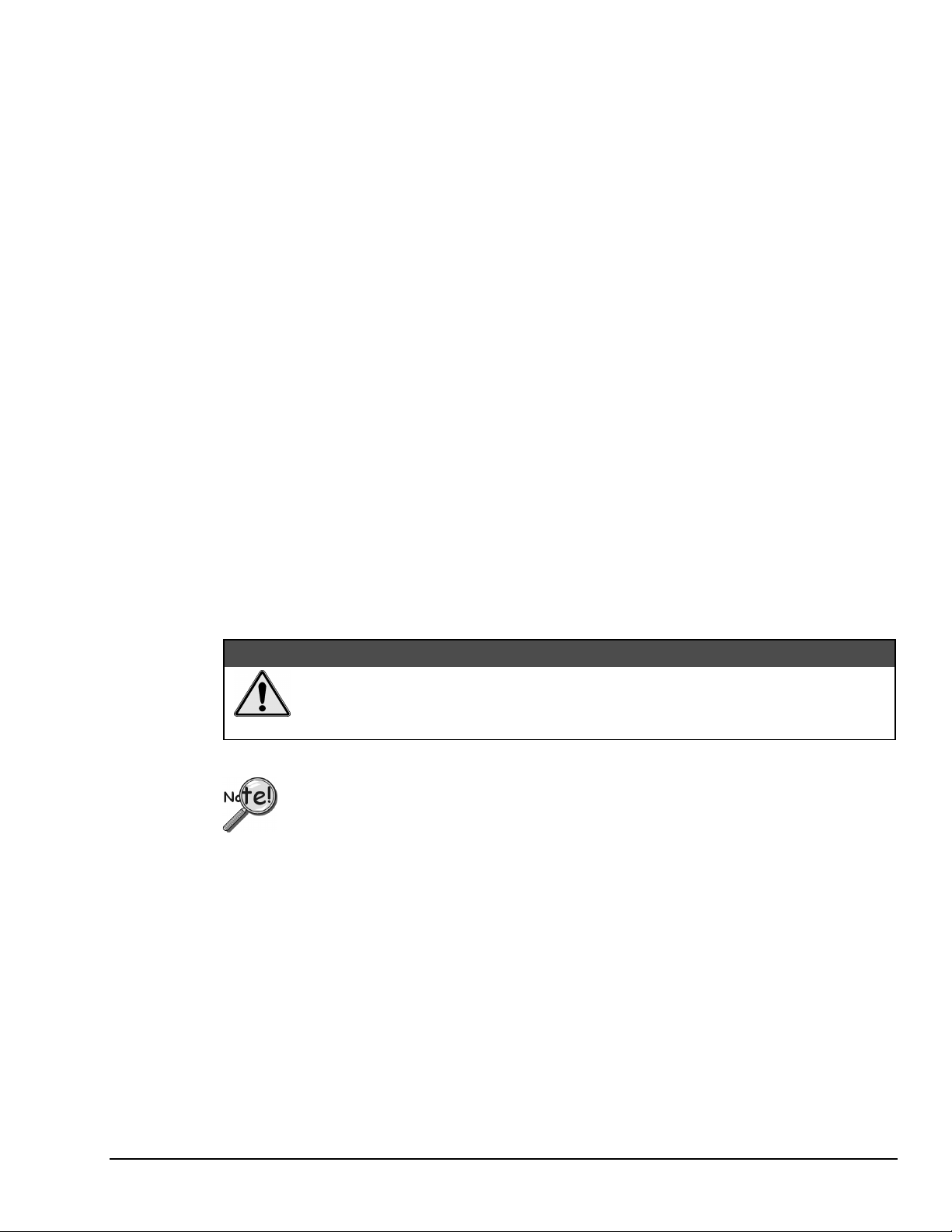
Physical Installation
To Install the DynaRes Board
1. TURN THE COMPUTER OFF. Never remove the cover of the computer without first turning the
power switch off.
2. Open the Computer Remove the cover of the computer. (If appropriate, refer to the computer’s
owner’s manual for more information about removing the cover and installing enhancement boards.)
3. Ground Yourself While holding the board, before installing it, touch the metal chassis of the
computer to discharge any static electricity that might be on the surface of your body.
This is important, as static electricity can damage electronic parts. (Likewise, if you ever remove the
board from the computer, always store it in its protective shipping bag.)
4. Remove Plate At the back panel of the computer, unscrew and remove the narrow dust cover plate
that is directly behind the expansion slot you want to use. (Keep this screw handy.)
5. Insert the Board Push the edge of the DynaRes board having “gold fingers” down and into the
expansion slot (socket) on the chassis, making sure that the contacts align with the socket and the
spring latches are through the socket. Then plug it in by pushing the board straight down. (NOTE: If
you are using a DynaRes 16, a second expansion slot is required for the second cable connector.)
6. Fasten the Board to the Chassis Install the “left over” screw from step 4. Place it in the original hole,
through the DynaRes board’s bracket, so that it fastens the top of the bracket to the computer’s back
panel.
Next Steps
7. Connect the Cable to the Terminal Panel Plug the cable’s connector into the socket on the terminal
panel (please refer to your terminal panel’s manual, if you are unsure about the correct position).
&$87,21
Incorrect installation of these cables can damage the data acquisition board or the
terminal panel. If you are uncertain about proper placement,
please see “Terminal Panel Connections” at the beginning of this discussion, and
inspect the diagram on page 4 – 2 .)
If you are going to measure current, please see “Measuring Current” on the next page.
Single Board Usage – If you intend to run with a single data acquisition board in your system, you are now
ready to install your application software and to connect sensors to your terminal panel.
Multiple Board Usage – If you are going to use more than one data acquisition board, now it’s time to set
each Board Number Switch to an unique number. Follow the steps in the “Setting the Board Number
Switch” section in this chapter on page 4 – 4.
Installing the Software – For information on loading and configuring our DASYLab or QuickLog PC please
refer to the user guide for that application package.
Installing the Terminal Panels – To learn how to connect experiments to the terminal panel see your
terminal panel owner’s manual, or our Applications manual (which discusses data acquisition and control in
general and provides examples of uses for the products).
DataShuttle and DynaRes
11-09-01
Installing the DynaRes 4-3
Page 44

Measuring Current
If you are going to connect a current, rather than a voltage, to one or more of the analog input channels,
then make certain to set the “Current/Volt” switch for that channel on the terminal panel. These switches are
located under the daughterboard on the T71 terminal panel (see Terminal Panels manual for illustration).
Moving a switch to the “Current” position selects current, placing a precision 24.9Ω, 0.1% resistor in the
circuit for that channel.
Two kinds of misuse can burn out the board’s input sense resistors:
Do not apply a voltage to a channel whose setting is for current.
Also, do not apply more than 50 mA to a channel set for current.
Setting the Board Number Switch
Multiple Boards
When you are using multiple boards in your installation, each board needs to have an identity for the
software to recognize it as an “individual.”
The Board Number switch on a board accomplishes this, as it enables you to set an identifying number for
the board (see the illustration on page 4 – 2).
This number determines, among other things, the sequence in which the software reads multiple boards
(application programs can address as many as 15 boards).
&$87,21
When using more than one DynaRes product in your installation, every board’s Board Number switch needs
to have a different number setting, and all switches are to be in number sequence, starting with 1. For
example, if you are using three boards, the board number sequence would be 1, 2, 3. Set the address and
interrupt on all boards to the same settings.
Single Board
If your system includes just a single data acquisition board, then you don’t need to have much concern
about the Board Number switch.
When your DynaRes leaves our manufacturing facility, we set the Board Number switch to 1, and this is the
setting we recommend for most purposes when you are using only one board in your installation.
Disabling Boards
If you want to disable the board, for any reason, set its Board Number switch to 0. This is handy if you want
to use fewer boards: that way you don’t have to remove them from the computer. Remember, however, that
all remaining boards must have their board numbers in a continuous sequence.
Setting the Switch
To Set the Board Number Switch
1. Locate the Switch With the cover of your computer removed, examine the illustration on page 4 – 2 in
this chapter and find the “Board Number Switch” on the DynaRes.
On the printed circuit board, this is a rotary switch with the label “BRD SEL.”
2. Make the Setting Note that the switch has 16 possible positions: numbers on the detents are 0 through 9
and A through F.
4-4 Installing the DynaRes
11-09-01
DataShuttle and DynaRes
Page 45

Determine which is to be the First Board. (This is easy, if it is the sole board.) Then turn its dial to 1.
Determine which is to be the Second Board, then set its switch to 2.
Continue to set the switches for all boards in your installation to unique numerical values in an unbroken
sequence.
(As various models of our boards use different kinds of switches, please see their owner’s manuals for an
explanation of how to set switches on other boards.)
Setting the Base Address
The Base Address determines the logical system address where the personal computer expects to find all
data acquisition boards. Base Addresses must be the same on all boards.
The factory setting for all of our data acquisition products is 300H (in hexadecimal format).
It is rarely necessary, but if you have difficulty getting the board to work, you can change these switches to
values different from the factory settings. (Another device in your PC, for example, might be trying to use
the same Base Address.)
Indications of this are: if the program reports it cannot find your board, or if it reports fewer boards than
you really have, or if another board starts to work improperly after you install the DynaRes.
These problems indicate interference with another board using the same base address as the DynaRes
product.
Remedy the problem by changing the switches of all data acquisition boards to an address that has no
conflict. (If you have boards other than DynaRes in your system, please refer to their owner’ s manuals for
instructions on how to change their settings.)
Setting DynaRes Base Address
To Set the Base Address
1. Locate the Address Switches Remove the cover of your computer over the data acquisition board, and
find the location of the Base Address switches. Refer to the board illustration on page 4 – 2 in this chapter
and find “Base Address Switches” on the DynaRes diagram.
On the printed circuit board itself, this is a block of four DIP switches.
Note: Depending on the space available in your installation, it might be necessary to remove the board to
reach the Base Address Switches. If so, please follow the same precautions as in “Physical
Installation” on page 4 – 3.)
2. Change the Setting 300H is the normal base address. It consists of all four DIP switches’ being in the
“up” position (when the board is sitting in the computer’s expansion slot).
The DIP switches have the labels “1” through “4.” Sliding a switch to the “down” position adds a value to
300H:
DynaRes Base Address Switch Additive Values*
Switch Position To 300H Add
1 Down 10H
2 Down 20H
3 Down 40H
4 Down 80H
* As the switches are additive, your sliding Switches 1 and 4 down, for example, is going to add 10H and
80H to the 300H, equalling 390H.
DataShuttle and DynaRes
11-09-01
Installing the DynaRes 4-5
Page 46

Base Address Settings
Value Switch Positions*
300H U U U U Factory setting
310H D U U U 320H U D U U May interfere with hard disk drive
330H D D U U 340H U U D U Recommended alternative
350H D U D U 360H U D D U 370H D D D U May interfere with parallel printer
380H U U U D -
390H D U U D 3A0H U D U D 3B0H D D U D 3C0H U U D D 3D0H D U D D May interfere with graphics adaptor
3E0H U D D D -
3F0H D D D D May interfere with floppy disk drive
* U = Up D = Down
Possible DynaRes Base Address Settings
Comments
1 2 3 4
Changing Hardware Interrupts
For users of Windows programs that employ hardware interrupts, the DynaRes board provides for changing
the interrupt number, if necessary.
Refer to page 4 – 2 to locate the interrupt jumper block on the DynaRes board. By repositioning the jumper,
which is a plug, to another socket on the block, you can select another of these interrupts: IRQ2, IRQ5,
IRQ7, IRQ11, IRQ12, or IRQ15. (Remember that on AT computers the IRQ2 selection is actually the IRQ9
line.)
4-6 Installing the DynaRes
11-09-01
DataShuttle and DynaRes
Page 47

DynaRes - Technical Notes 5
Overview
Although operations in this chapter are seldom necessary during everyday data acquisition, you might want
to refer to them at certain times during operation of the DynaRes. They are
•
Pinouts (at the board’s connectors in the event you want to connect analog or digital signals directly,
without using a terminal panel; refer to pages 5 – 1);
•
Block diagram of the DynaRes showing on-board processing (see page 5 –2);
•
Recalibration of all DynaRes on-board references to bring the accuracy of the product to factory
specifications (see page 5 – 3);
•
Using EDITCAL to edit calibration files on EEPROM to accommodate changes to your installation,
or to restore missing files (on page 5 –3);
•
Note for DOS users with respect to the Analog Connection Development System
(see page 5 – 4);
•
Troubleshooting: some possible problems and solutions after installing, and during operation of the
DynaRes (starting on page 5 – 4).
Pin Assignments
DataShuttle and DynaRes
Pinouts of the DynaRes 8 and Channels 1-8 on the DynaRes 16
(at Back Panel Connector)
11-13-01
DynaRes - Technical Notes 5-1
Page 48
Block Diagram
Pinouts of Channels 9-16 on the DynaRes 16
(at Back Panel Connector)
5-2 DynaRes - Technical Notes
Block Diagram of the DynaRes (All Models)
11-13-01
DataShuttle and DynaRes
Page 49

Recalibration
Your DynaRes uses an exclusive calibration technology to achieve great stability, typically requiring
no adjustment for years. Please see the Warranty Card for your exact guarantee of calibration.
Factory Methods
Instead of employing adjustment potentiometers to calibrate the board, our technicians test and calibrate
each DynaRes after assembly. They then enter that board’s unique calibration number values into
EEPROMs on the board; we also print the same numbers on a label on the board itself.
Whenever you use our software with the board thereafter, the programs read the factory’s calibration
numbers from the EEPROM, and automatically make minor compensations for real-world conditions
(for instance, for cold junction properties of a thermocouple).
Recalibration
Under normal conditions, no full recalibration of the DynaRes is necessary.
(If you ever suspect that your DynaRes is out of tolerance, please call Technical Support for advice.
If it requires recalibration, we can perform the work for you at our facility using the same high accuracy test
equipment we use during the manufacturing quality assurance process.)
Only if your organization is proficient in such techniques, and only if you have the necessary equipment,
do we encourage you to proceed with recalibration (and please contact our Technical Support Department
for guidelines).
For most customers, we recommend returning the board to our Technical Services Department, instead.
EDITCAL Utility
EDITCAL.EXE (or EDITCAL, for short) is the utility program that simplifies the modification of values in
the EEPROM.
Starting Editcal
Make sure the EDITCAL.EXE program file is in the same sub-directory as the application programs.
At the DOS prompt, enter EDITCAL, then press the [ENTER] key. (This invokes the utility.)
EDITCAL Selections
To Select a Function
1. Use the arrow keys to navigate back and forth among these menu selections:
2. Move the arrow keys until the selection you want is flashing.
DATA FILES - To merge calibration files supplied from the factory into a single file for systems
that have multiple boards, or to update existing calibration file (not for use with DynaRes boards).
AC EEPROM - To view or modify calibration data on Analog Connection boards (including
DynaRes boards) that have non-volatile on-board EEPROMS.
QUIT - Ends this EDITCAL session.
3. Press [ENTER].
DataShuttle and DynaRes
11-13-01
DynaRes - Technical Notes 5-3
Page 50

Troubleshooting: Installation
If you experience difficulty in getting your data acquisition board up and running, please check to see that
the installation is according to the descriptions in Chapter 4.
If the software reports a board failure, or that it cannot find a board, then try these remedies:
1. Confirm that the board is seated properly in the PC expansion slot (reseat it, if necessary; see the
illustration on page 4 – 2).
2. Verify the Board Number switch is not set to “0.” (See page 4 – 4).
3. Use a different Base Address. It is possible that another device in your installation is trying to use the
same Base Address (see the explanation on page 4 – 5). You may optionally specify this new number
in the STI_DRV.INI.
4. If there is more than one data acquisition board in your installation, make sure they all have the same
Base Address and interrupt, but sequential Board Numbers, starting with 1.
5. Install the board in another open slot in the PC (follow the instructions on page 4 – 2).
6. Remove other devices from expansion slots in your PC to check whether they are conflicting with
your DynaRes board.
7. Verify that the software is up to date (a version compatible with the board you are using. Contact
your software provider or us).
8. Try different IRQ levels. If you are operating under our Windows software, change the IRQ level on
the jumpers on your data acquisition board (see illustration on page 4 – 2 to locate these jumpers).
You may want to specify this new number in your STI_DRV.INI file. Alternatively, you may change
the IRQ levels of other hardware in your computer. If using QuickLog, check for
[386Enh]
DEVICE=C:\QLFW\STIDATAQ.386
in System.ini file
9. Remove other software drivers that may conflict with ours.
10. If possible, install the board in another computer to verify its correct operation.
11. Try alternate bus timing jumpers. On some models of computers, the Address Latch Enable (ALE)
timing is not compatible with our data acquisition boards.
To try the alternate (falling edge) timing, locate jumpers JP5 through JP8 on the data acquisition board. The
normal (rising edge) timing position is JP6 and JP8. To change this, you need to cut these traces with a
sharp knife, then solder a wire across JP5 and JP7.
(NOTE: This alternate connection may not work in all models of computers.)
If You Need Customer Support
What to do before calling technical support, to help us serve you better:
1. Have the part numbers of your boards and terminal panels ready.
2. Have the type and version number of the software you’re using.
3. Have your computer’s type, model, and the version of the operating system.
5-4 DynaRes - Technical Notes
11-13-01
DataShuttle and DynaRes
Page 51

Troubleshooting: Operation
Hints
During operation, it’s good practice to short all analog input channels you’re not using; to do this,
connect + to – to Com.
It’s essential to have exactly one ground reference per channel. This single connection to ground makes sure
you don’t exceed the common mode range of input.
(More than one connection per channel can lead to ground loops, causing errors or erratic readings.
Connecting the – to the Com terminal provides a single ground. Your sensor might also provide another
ground. If you’re not sure that your sensor is grounded, try connecting the – to Com, and not, and see which
works best.)
Remember that if speed is not critical, selecting the “low noise mode” in software always provides the best
accuracy and resolution with your data acquisition board.
Operating Qs And As
1. Problem: My board reads analog inputs wrong.
Action: Make sure the calibration numbers in the EEPROM are correct (see the discussion beginning
on page 5 – 6 in this chapter). If the figures are correct, try shorting + to – to Com: the board should
return a reading around 0V.
2. Problem: My board reads the thermocouple as a very negative temperature.
Action: Verify the connections are secure. Opens read as negative temperature.
3. Problem: My board reads thermocouple input wrong.
Action: Confirm that the CCAL number in the EEPROM matches the number on the terminal panel’s
calibration label.
(If you need to use a general-purpose terminal panel – one that doesn’t have a factory CCAL number
– with a thermocouple, you can achieve approximate results by entering a CCAL of 22000. Then
change the figure by about 75 points for each degree C. that you want to raise the temperature.)
4. Problem: My readings are noisy.
Action: Try using the low noise mode (see your software manual for more information).
5. Problem: My board used to work, but now the software cannot find it, or reports an error.
Action: Check to make sure the Board Number switch is not set to “0.”
If You Need Customer Support
What to do before calling technical support, to help us serve you better:
1. Have the part numbers of your boards and terminal panels ready.
2. Have the type and version number of the software you’re using.
3. Have your computer’s type, model, and the version of the operating system.
DataShuttle and DynaRes
11-13-01
DynaRes - Technical Notes 5-5
Page 52

Product Specifications: DynaRes 8/16
Specifications of the DynaRes 8 and DynaRes 16
Accuracy DynaRes 8/16 General Conditions
Range Typical Resolution
at Full Scale
-5 to +50 mV 0.8 µV 0.04% –
-25 to +25mV 0.8 µV 0.08% –
-50 to +500mV 8 µV 0.01% 0.05%
-250 to +250 mV 8 µV 0.01% 0.05%
VOLTAGE
General Conditions – From 15 to 35 degrees C. ambient at the interface board, source resistance less than
1k Ohms. Includes linearity, drift, offset, resolution, and calibration error. 16 bit (0.0015%) resolution in
use.
Thermocouple Conditions – Same as General Conditions. Does not include the accuracy of the
thermocouple itself (cold junction error must be added in; cold junction compensation with T21 terminal
panel only; please see your terminal panel manual’s specifications for cold junction compensation error).
Resolution assumes 16 bit resolution in use; it is approximate because resolution varies with temperature.
Thermocouples use the 50 mV range. For inputs below -5 mV (below approximately -100 degrees C.) use
the +/-25 mV range. For the best resolution use the 50 mV range above -5 mV.
-1 to +10 V 150 µV 0.01% 0.05%
-5 to +5 V 150 µV 0.01% 0.10%
Absolute Accuracy, the Larger of
% of Range: % of
Reading:
5-6 DynaRes - Technical Notes
11-13-01
DataShuttle and DynaRes
Page 53

DynaRes 8/16 Thermocouple Accuracy
Type Range (°C.) Resolution (°C.) Accuracy (°C.)
J -210 to -100 0.02 – 0.04 ± 1.2
-100 to 100 0.02 ± 0.7
100 to 880 0.01 ± 0.5
K -250 to -150 0.03 – 0.15 ± 4
-150 to -50 0.03 ± 1
-50 to 1260 0.02 ± 0.7
E -250 to -100 0.08 – 0.01 ± 2
-100 to 200 0.01 ± 0.6
200 to 680 0.01 ± 0.4
T -250 to -120 0.03 – 0.1 ± 3
-120 to -25 0.02 – 0.03 ± 0.9
-25 to 200 0.01 – 0.02 ± 0.7
200 to 400 0.01 ± 0.5
S -50 to 50 0.1 – 0.2 ± 5
50 to 300 0.1 ± 3
300 to 1770 0.08 ± 2
R -50 to 25 0.1 – 0.2 ± 5
25 to 200 0.1 ± 3
200 to 1770 0.08 ± 2
B 200 to 300 0.25 – 0.4 ± 10
300 to 500 0.15 – 0.25 ± 6
500 to 1000 0.08 – 0.15 ± 4
1000 to 1820 0.08 ± 2
G 25 to 200 0.08 – 0.3 ± 8
200 to 2315 0.08 ± 2
D -20 to 2315 0.04 – 0.08 ± 2
300 to 1500 0.04 ± 1.3
C -20 to 2315 0.04 – 0.08 ± 2
100 to 1500 0.05 ± 1.5
N -200 to -100 0.05 – 0.1 ± 3
-100 to 1300 0.02 – 0.05 ± 1.5
Set Resistor
DataShuttle and DynaRes
DynaRes 8/16 RTD Accuracy
RTD
Ω
Ω
Range
°C.
Resolution
°C.
Accuracy
°C.
10 k 50 -200 to 115 0.005 0.8
20 k 50 -200 to 525 0.01 0.9
20 k 100 -200 to 115 0.005 0.8
50 k 50 -200 to >850 0.03 1.4
50 k 100 -200 to 750 0.01 1.0
50 k 200 -200 to 115 0.005 0.8
100 k 100 -200 to >850 0.03 1.4
100 k 200 -200 to 750 0.01 1.0
100 k 500 -200 to 115 0.005 0.8
200 k 200 -200 to >850 0.03 1.4
200 k 500 -200 to 525 0.01 0.9
200 k 1000 -200 to 115 0.005 0.8
500 k 500 -200 to >850 0.03 1.4
500 k 1000 -200 to 750 0.01 1.0
1000 k 1000 -200 to >850 0.03 1.4
11-13-01
DynaRes - Technical Notes 5-7
Page 54

RTD Conditions – Same as General Conditions. It does not include the accuracy of the RTD sensor itself.
RTD Conditions includes linearization and signal conditioning errors. Resolution assumes 16-bit resolution
is in use. RTD measurements are on the 50 mV range.
Stability
Accuracy specifications in this chapter already reflect these temperature drift errors for temperatures from
20° through 40° C.:
I
n many applications, stability and noise can be more important than absolute accuracy. This is
“repeatability.” Calculate the repeatability of a reading by adding together the stability and noise for the
range you want.
Input Impedance
The DynaRes 8/16 Ultra has an input impedance of > 20 MΩ.
Noise Rejection
Important: All noise measurements are in low noise mode.
DynaRes 8/16 STABILITY
Range % per °C. % Over a Year
50 mV ± 0.001 ± 0.02
± 25mV ± 0.001 ± 0.02
all other voltage ranges ± 0.0025 ± 0.03
CMRR – The Common Mode Rejection Ratio (CMRR) is >20 dB. Conditions for CMRR: DC to 400 Hz,
common mode input ± 7.0 Volts channel to ground. This specification applies even when one or more
nonmeasured channels exceeds the operating common mode range.
Common Mode Range
Operating, channel-to-ground – ±7 Volts
Nonoperating – 50 Volts continuous, 150 Volts for one second, nonrepetitive.
Input Protection
50 Volts continuous. 150 Volts for one second, nonrepetitive.
DynaRes 8/16 Noise Rejection
Range Typical Internal Noise (RMS)
50 mV 0.5 µV
± 25 mV 0.5 µV
500 mV 2.5 µV
± 250 mV 2.5 µV
10 V 50 µV
± 5 V 50 µV
5-8 DynaRes - Technical Notes
11-13-01
DataShuttle and DynaRes
Page 55
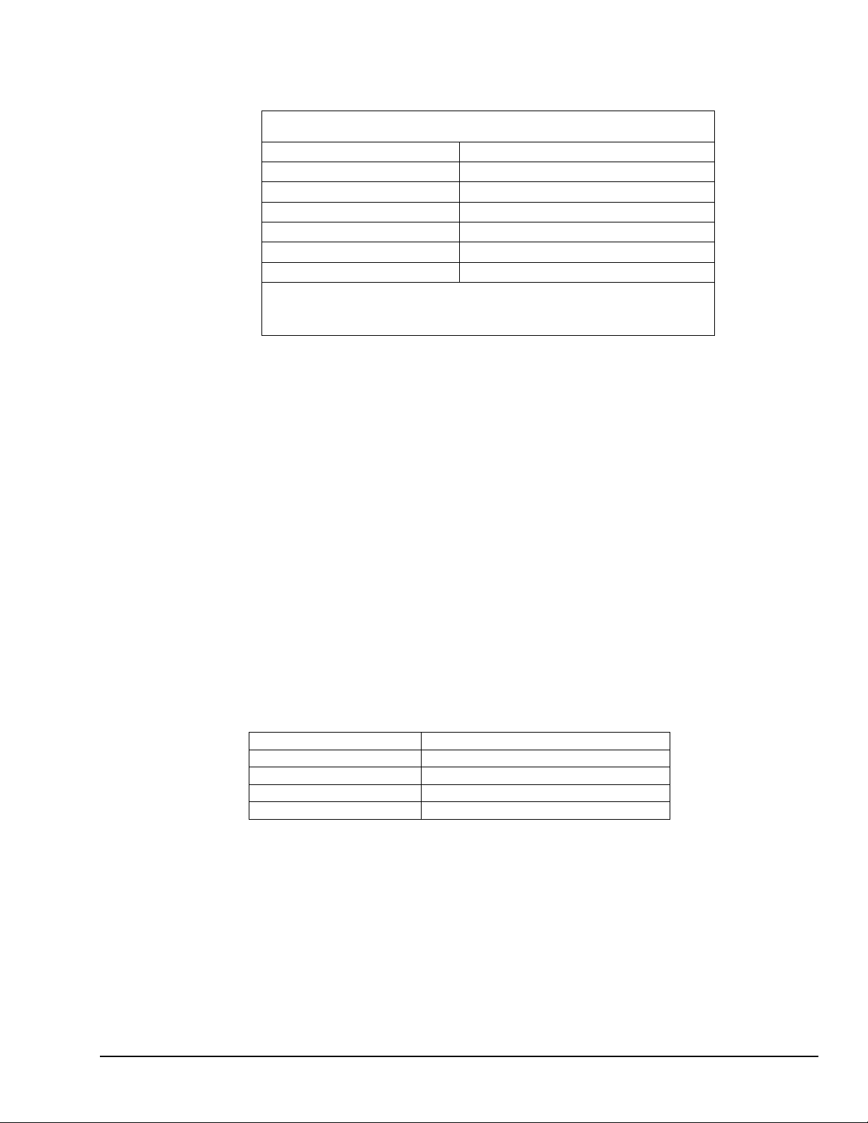
Resolution/Scan Rate
Selectable in software:
Scan rate is the rate in Hertz (or, samples per second) to read data into memory, including the time it takes
to switch channels and ranges. To calculate the total scan time for all channels, divide the rate by the
number of channels.
Digital I/O Channels
The DynaRes 8/16 has 8 or 16 digital I/O lines, with each line individually selectable as input or output.
These channels are TTL- and MOS- compatible as they come out of the board.
DynaRes 8/16 Resolution And Scan Rate*
Resolution at Full Scale Scan Rate
low noise mode: 0.0004% 45/55 Hz
16 bits: 0.0015% 200 Hz
15 bits: 0.003 % 300 Hz
14 bits: 0.006 % 500 Hz
13 bits: 0.012 % 700 Hz
12 bits: 0.024 % 900 Hz
* Rates describe an IBM PC 486DX2 66MHz running DASYLab under
Windows 3.1 with Tolerate Error=0. Rates are somewhat faster in faster
computers. Please also see “Dynamic Resolution” on page 3 – 2.
Their outputs sinks are open collector and are 3 milliAmperes; as inputs they draw no current. (Please see
the specifications in your terminal panel owner’s manual for open collector output.)
Counter/Timer
The DynaRes 8/16 has one on-board 16 bit counter/timer with 2 MHz internal clock. The counter timer is
connected to Digital I/O lines 9–12 on Terminal Panel 2 or to CT Gate, CT Out, CT In, and CT Trig on
Terminal Panel 1.
General Conditions
Maximum Voltage on any terminal – 150V
Maximum Current on any terminal – 1A
Auxiliary Power Supplies – +5V, +12V, or -12V, direct from the computer’s power supply. The +6.9V
supply draws it’s current from the +12V supply.
+6.9V Supply Tolerance – ± 5%
· Temperature Coefficient: < 0.0005% per ºC
· Stability: < 0.01 per year
Voltage Maximum Current
+6.9V 20mA
+12V 200mA
+5V 100mA
-12V 200mA
DataShuttle and DynaRes
11-13-01
DynaRes - Technical Notes 5-9
Page 56

Operating Temperature Ambient – 0 to 50 degrees Celsius.
Physical Dimensions– 6.7" x 4.0" (17.0cm x 10.2cm)
DynaRes 8/16 Ultra Current Consumption*
Voltage Supply Current Consumed by
DynaRes 8 Ultra: DynaRes 16 Ultra:
+5V 317mA 335mA
+12V 10.5mA 13mA
-12V 1.6mA 2.5mA
Total 1.73 Watts 1.861 Watts
* Measurements are made after loading GDRV and GFIND, with no connection
to terminal panel.
5-10 DynaRes - Technical Notes
11-13-01
DataShuttle and DynaRes
Page 57

Introduction to Terminal Panels 6
For most data acquisition applications using a plug-in board, it is also necessary to install a terminal panel.
Terminal panels serve as a convenient interface between the real-world and the computer, providing screw
terminals for connections to sensor wires and a 50-pin ribbon cable connected to the data acquisition board
inside the computer.
Multitudes of terminal panels are offered to assist you with all types of applications. This manual covers all
of our general purpose and temperature panels for the WB series boards: the T31, T71-GP, T71-TC, and
T71-RTD.
General Information
Features
All the terminal panels have connections for:
•
eight differential analog inputs;
•
at least 8 digital input and output inputs;
•
the +5V, +12V, and -12V power supplies from the computer; and
•
the reference voltage from the analog board.
Package Contents
Your terminal panel package should include:
•
a cold junction temperature compensation sensor; and
•
a 50-pin, one meter cable for connection to the data acquisition board
Types of Panels
There are three basic types of terminal panels:
•
General Purpose - -T31, T71-GP
•
Thermocouple - -T71-TC
•
RTD (resistance temperature detector) - -T71-RTD.
The features and benefits of the different types of terminal panels are discussed in the corresponding
sections of this manual.
Physical Installation
Installation very simply consists of attaching a cable connector to both the terminal panel and the data
acquisition board installed in your computer, as shown below. You are then ready to begin connecting the
sensors needed for your application.
DataShuttle and DynaRes
Terminal Panel Installation
11-12-01
Introduction to Terminal Panels 6-1
Page 58
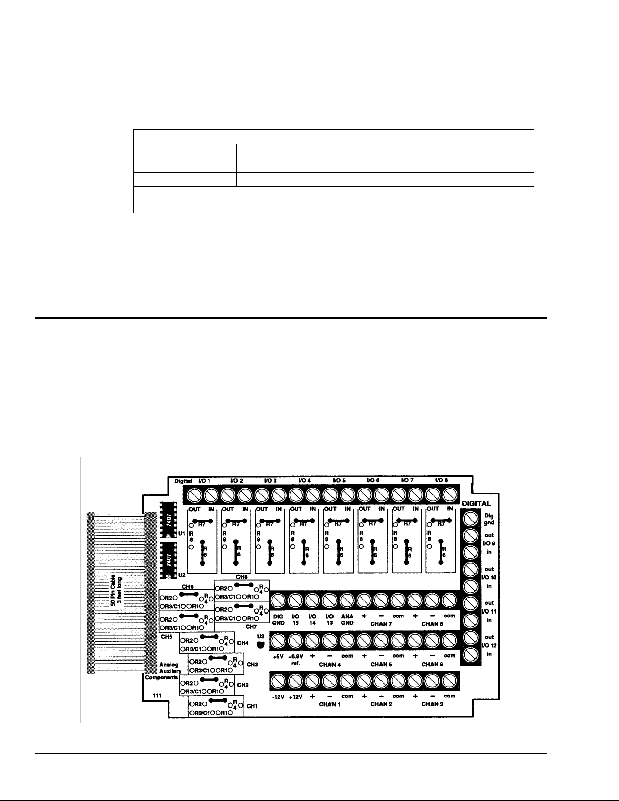
To Install a Terminal Panel
1. Verify that the panel is compatible with the installed board Not all terminal panels are compatible
with all data acquisition boards. Depending on the data acquisition board in use and on the type of
data to be collected, different terminal panels should be used. The table below indicates the correct
terminal panel under different conditions.
Product Model TC* GP RTD
ACAO-12 - T31 -
DynaRes T71-TC T71-GP T71-RTD
* The general purpose terminal panels can read thermocouples, but do not provide the same
high accuracy as the T71-TC.
2. Plug the terminal panel’s cable into the board All terminal panels connect to the installed data
acquisition board with one 50-pin cable.
The T71 terminal panels use a 50-pin Centronics cable, shipped separately, to connect to the data
acquisition board. To install, simply plug the cable into both the terminal panel’s and board’s connectors,
making sure to secure the spring latches to hold the cable in place.
Types of Terminal Panels
Terminal Panel Cross Reference
As was stated in the introduction, there are two basic types of terminal panels, each compatible with
different models of data acquisition boards.
T31 Terminal Panel
The T31 is a general-purpose terminal panel that provides screw-terminals for connecting up to
eight analog outputs and up to12 digital I/O lines.
6-2 Introduction to Terminal Panels
Illustration of the T31 Terminal Panel
11-13-01
DataShuttle and DynaRes
Page 59
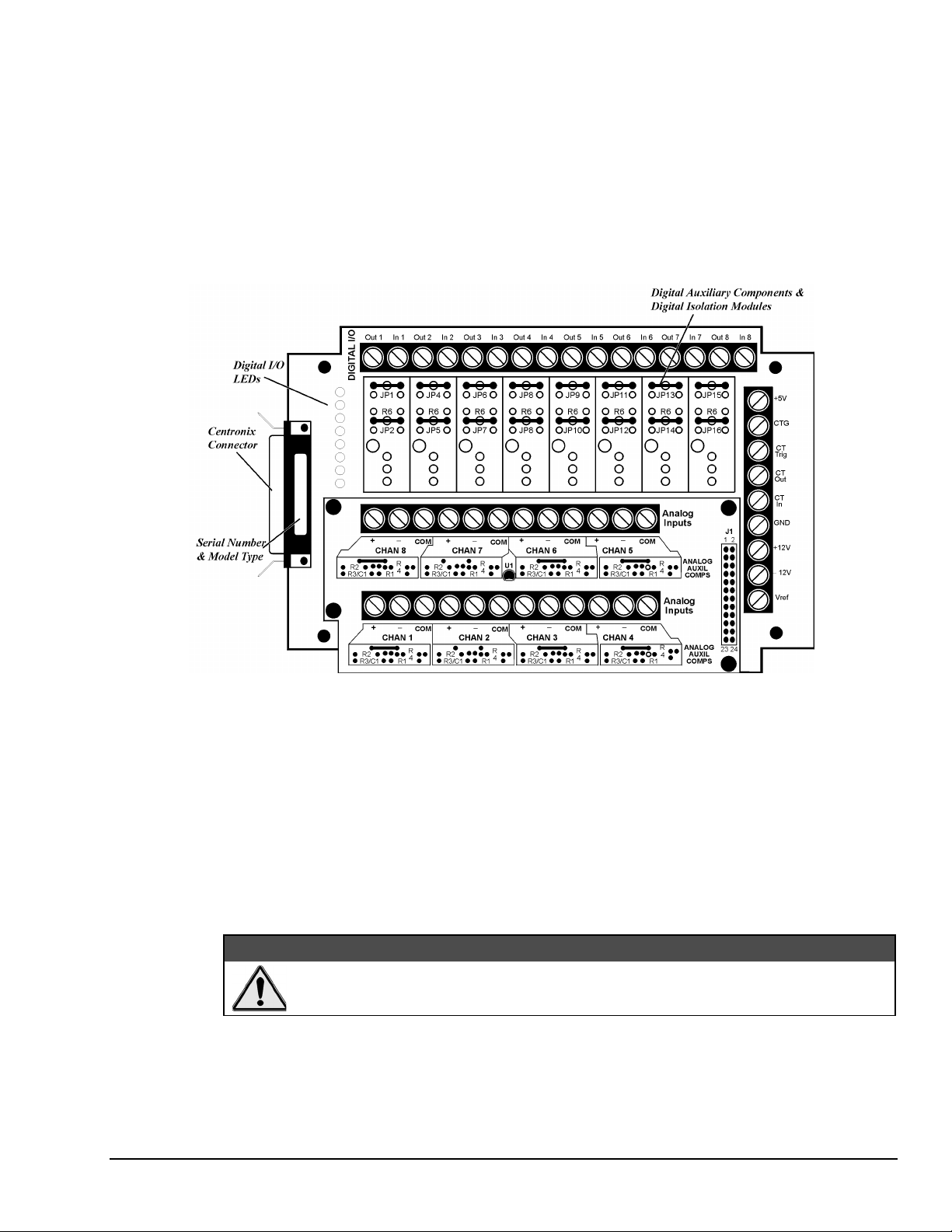
T71 Terminal Panel
Designed for use with the DynaRes data acquisition boards, the T71 terminal panel comes with a 3-ft.,
detachable M-M Centronics cable. The panel features terminals for eight analog inputs and eight digital I/O
lines, with room for up to eight digital opto-isolation modules.
There are three different models of the T71 terminal panel. The T71-TC is optimized for thermocouple
measurements, featuring a large aluminum isothermal plate with screw terminals for eight analog inputs.
The T71-RTD, specifically designed for high accuracy RTD measurements, has signal conditioning set
resistors pre-installed at the factory for use with two- or three-wire RTDs. The T71-GP model, pictured
below, is available for general-purpose measurements.
Illustration of the T71-GP Terminal Panel
Using the Digital I/O Lines – On-unit LEDs show the state of the digital I/O lines. “On” indicates that the
digital input or output is “low,” or that, if a digital output opto-isolator is installed on that channel, it is
energized.
Note that the state of the digital inputs will be “high”, if there is nothing connected. To change a line’s
default to low, a resistor (R1 for Channe1, R2 for Channel 2, etc.) must be moved to an alternate area (R1G
for Channel 1, R2G for Channel 2, and so on).
To Measure Current – There are eight dip switches, marked “Current/Volt,” located under the analog input
daughterboard. To measure current (4-20mA) on a channel, move the corresponding switch to the “Current”
position. This will connect a 24.9Ω, 0.1% resistor across the + and – inputs for that channel.
:$51,1*
Setting the switch to current may damage the resistors if a voltage in excess of 2.5V is
applied.
DataShuttle and DynaRes
11-12-01
Introduction to Terminal Panels 6-3
Page 60

Reference Tables
Each of the terminal panels differs from the others in some way, whether as a function of the signals to be
connected or of the plug-in board in use. In addition, some screw terminals on the panels have different
functions depending on which board is in use.
To assist you in making the proper connections, this section contains reference tables for the screw
connectors of each type of terminal panel. The panels are grouped according to the similarities in pin
connections and locations.
To use the following tables, first turn to the table for the terminal panel in use. Then find the function
desired in the left hand column. Under the board used will appear the label for the screw performing that
function
T31 Pin Connectors
Functions of the T31 Terminal Panels Pin Connectors
Function ACAO-12-XX
Dig I/O 9 N/A
Dig I/O 10 N/A
Dig I/O 11 N/A
Dig I/O 12 N/A
An Out 1 Chan 1
An Out 2 Chan 2
An Out 3 Chan 3
An Out 4 Chan 4
An Out 5 Chan 5
An Out 6 Chan 6
An Out 7 Chan 7
An Out 8 Chan 8
CT Out N/A
CT In N/A
CT Trig N/A
CT Gate N/A
Vref + 6.9 V
1. Actual voltage is 10V
N/A = Not Applicable
T71 Pin Connectors
Function DynaRes 8 DynaRes 16
CT Out CT Out Dig I/O Out 9
CT Trig CT Trig Dig I/O In 11
CT Gate CT Gate Dig I/O In 12
6-4 Introduction to Terminal Panels
Functions of the T71 Terminal Panel Pin Connectors
CT In CT In Dig I/O In 10
11-09--01
DataShuttle and DynaRes
Page 61

When two T71s are used with a 16-channel DynaRes, both terminal panels have access to the one
counter/timer on the board. The first T71 will access the counter/timer through the lines shown in the first
column above. The second T71 uses the lines shown in the second column. Both sets of lines cannot be
used at the same time.
Auxiliary Analog and Digital Components
Auxiliary Components
Auxiliary Components are required by some sensors, are used to protect digital signals, or are used to pull
digital outputs to a set level. There are two areas (one digital and one analog) on the terminal panels for
installing auxiliary components; schematics of both are shown in detail in Figures 10(a),(b), and (c) below
and on page 6-8. Note that each channel on the terminal panel has room for its own separate set of auxiliary
components.
When using analog auxiliary components R1, R2, and R5 you must cut the shorting metal trace that
connects the two ends of the line together before installing any of the components in these locations. Use a
sharp knife to carefully slice through the trace without cutting additional traces. In the case of R5 this is a
plastic covered metal wire. Diagrams of the auxiliary component area, hole functions, and connection
possibilities are shown on page 6-8.
Figure 10 Schematic for Analog & Digital Auxiliary Components
DataShuttle and DynaRes
11-12-01
Introduction to Terminal Panels 6-5
Page 62
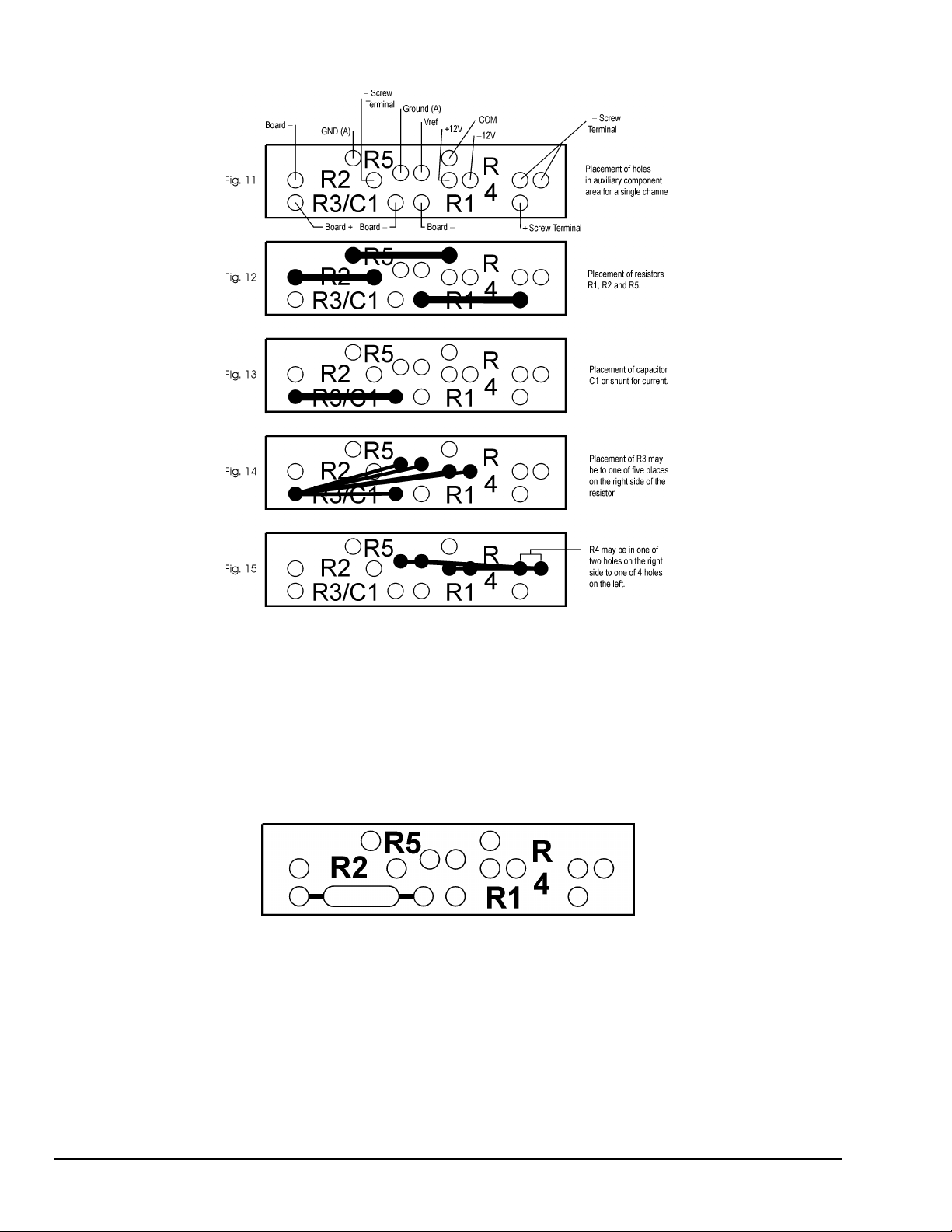
Examples
Analog Auxiliary Component Area on Terminal Panel
Example 1: Current sense resistor
The analog boards and terminal panels can measure currents up to 50mA directly. On the Analog
Connection boards and T71 terminal panels there is a 25Ω precision resistor on the unit itself; dip switches
allow users to selecting between voltage and current input. To measure current on any other type of board,
however, it is necessary to install 25Ω precision resistor on the terminal panel. This connection for current
measurement is shown below. (To see how this connection adds to the circuit, refer to Figure 10(a).)
Figure 16. Current Measurement Connection
R3 is used as a shunt resistor across the positive and negative lines of the channel in use. To install this
resistor, push the resistor ends through the holes for R3 (from the terminal side) until the resistor lies flat
with the panel surface. On the backside, solder the wires to the holes, and then clip off the extra wire with
pliers. This connection does not require any additional traces to be cut. Be sure to select current
measurement in the software package that you are using.
This installation allows the measurement of voltage across the resistor and the conversion of this
measurement to current using the equation V=IR. Observe the power rating of the resistor you install at R3.
Space is provided for a 1/4 Watt resistor.
6-6 Introduction to Terminal Panels
11-09--01
DataShuttle and DynaRes
Page 63
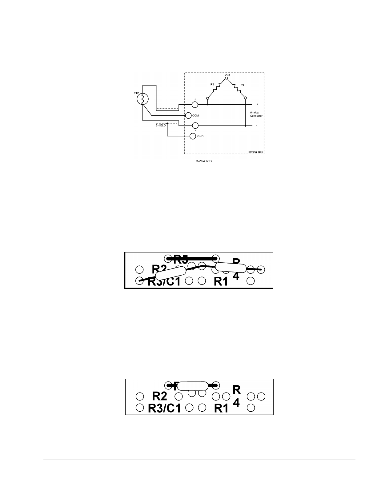
Example 2: 3-Wire RTD components
The most popular connection for RTDs is the three wire type. This sensor requires the installation of
resistors R3 and R4 except for these DataShuttle RTD model, where both resistors are already installed
Consult Set Resistor Values on page 5-7 for R3 & R4 values. Both resistors are already installed in the
T71-RTD panels.
Figure 17. 3-Wire RTD Components
However, if you need to install these resistors yourself then do the following: Figure 14 and Figure 15 show
the possible locations of R3 and R4. Figure 11 will show you that R3 and R4 need to be connected as in
Figure 18. R5 is already in place and should not be removed. To install these resistors push the resistor ends
through the holes for R3 and R4 as shown in Figure 14 (from the terminal side) until the resistor lies flat
with the panel surface. If two wires cannot fit into the Vref hole then one wire may be soldered to another
that is already inserted. On the backside, solder the wires to the holes. Then clip off the extra wire with
pliers. The auxiliary component area in question will now look like Figure 18 below. This connection does
not require any additional traces to be cut.
Example 3: Ground loops
Occasionally there is an installation where the ground connection is made at the sensor, but it is not reliable.
The solution to this “intermittent” ground is to replace the COM to GND(A) jumper wire at R5 (Figure
10(a)) with a 10 MW, 5%, 1/4 Watt resistor. This provides a ground reference for the analog inputs in
question, but allows very little ground current to flow. In very noisy environments with intermittent
grounds, a smaller resistor may be used if the readings are erratic. This connection is shown is Figure 19
below.
DataShuttle and DynaRes
Figure 18. 3-Wire RTD Connection
Figure 19. Ground Loop Connection
11-12-01
Introduction to Terminal Panels 6-7
Page 64
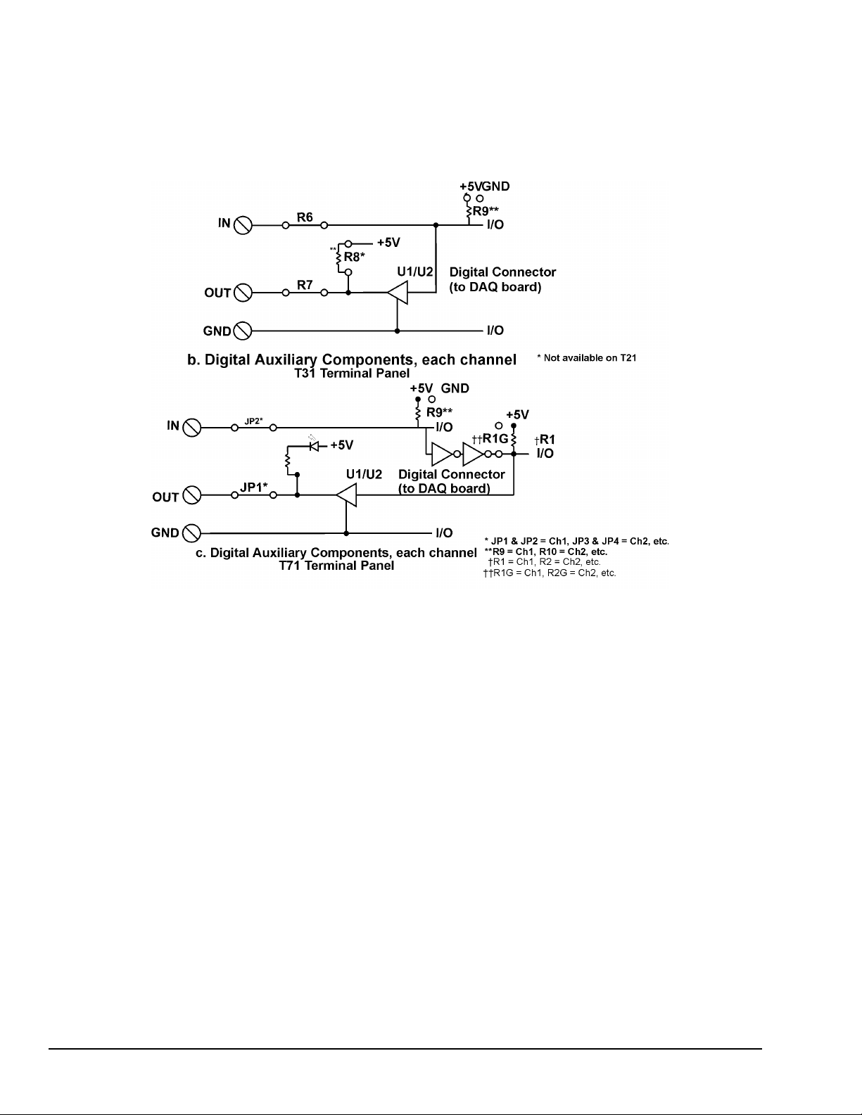
To install this resistor the wire at R5 must first be removed. After R5 has been removed, push the resistor
ends through the holes for R5 (from the terminal side) until the resistor lies flat with the panel surface. On
the backside, solder the wires to the holes. Then clip off the extra wire with pliers. The auxiliary component
area in question will now look like Figure 19. This connection does not require any additional traces to be
cut.
Digital Auxiliary Components
Figure 10 (Cont.) Schematics for Digital Auxiliary Components
Installing Digital Modules
Modules are available to safely connect the digital I/O lines to high voltage AC and DC sources. There are
four basic types:
•
AC output: to switch AC power (relay)
•
DC output: to switch DC power (relay)
•
AC input: to sense AC voltage
•
DC input: to sense DC voltage
The output types are used to switch loads on and off. The input types are used to sense the high/low status
of a signal. All of the modules provide optical isolation between the high voltage and terminations.
These modules may be installed on the T31 and T71 terminal panels. First, remove the jumpers labeled R6
and R7. This disconnects the digital I/Os from the terminals. The module will not fit into the panel until
these jumpers are removed. Then, simply insert the module and fasten a #4-40 nut to the retention screw.
Then, on the back of the terminal panel, solder the leads of the module to the panel.
6-8 Introduction to Terminal Panels
11-09--01
DataShuttle and DynaRes
Page 65

The terminals for that I/O have now changed their function from low voltage I/O to high voltage isolated
I/O. The two terminals become one input channel (high and low lines), or one output channel (like relay
contacts), depending on the type of module you have installed.
When using these terminals as input lines, be sure to connect the positive line to the
old OUT terminal and the negative line to the old IN terminal. Failure to do this will
result in the module not switching.
Installing Pull-up Resistors
As noted in the Applications Reference Manual and previously in this manual, the digital outputs are open
collector and must have a power source connected in order to drive loads. Merely connecting the output
terminal through a load (such as a bulb) and then to digital ground will not work. In this case, a pull-up
resistor connecting the output terminal to a power supply will complete the circuit.
This pull-up resistor is installed in position R8, as shown in Figure 10(b), which connects the output to the
board’s +5V power supply. The Figure on page 6-2 shows the physical location of R8 on the T31 terminal
panel. Note that R8 is not available on the T71 and may have to be installed manually between the +5V
supply and the output terminal in question.
To install this resistor, push the resistor ends through the holes for R8 (from the terminal side) until the
resistor lies flat with the panel surface. On the backside, solder the wires to the holes. Clip off the extra wire
with pliers. This connection does not require any additional traces to be cut. Use a 4.7K resistor to give 1
mA current flow or a 2.3K resistor to give 2mA current flow.
&$87,21
Troubleshooting Q & A
1. Problem: Why can’t I measure any voltage change with my voltmeter on my digital output?
Action: With nothing but a voltmeter connected, this is normal (except on T71 panels, which have
pull-ups installed). The digital outputs are termed “open collector.” These kind of outputs do not
supply any voltage, it must be supplied from another source. This allows the flexibility to use any
supply voltage up to 30V. The easiest way to see the state of an output terminal is to check the state of
the input terminal with a voltmeter.
2. Problem: My digital inputs are “high” with nothing connected to them.
Action: This is normal. The digital inputs are pulled up to about 1.5 volts by leakage from the
LS7407 chips. This is enough to read as a logic high. You can pull them down with a 470Ω resistor to
ground. If you remove the LS7407 chips the inputs will be low, but the outputs will be disabled.
(NOTE: On T71 panels, inputs will default to low if R10 is moved to GND.)
3. Problem: Can I get an output signal from the input terminals?
Action: Yes, you can use an input terminal to drive light loads such as a TTL input (except on T71
panels).
4. Problem: What should I do with the jumpers connecting the analog input to COM?
. Action: In general, it is best to leave them connected as shipped. Unless using thermocouples
connected to a common ground point on multiple units
DataShuttle and DynaRes
11-12-01
Introduction to Terminal Panels 6-9
Page 66
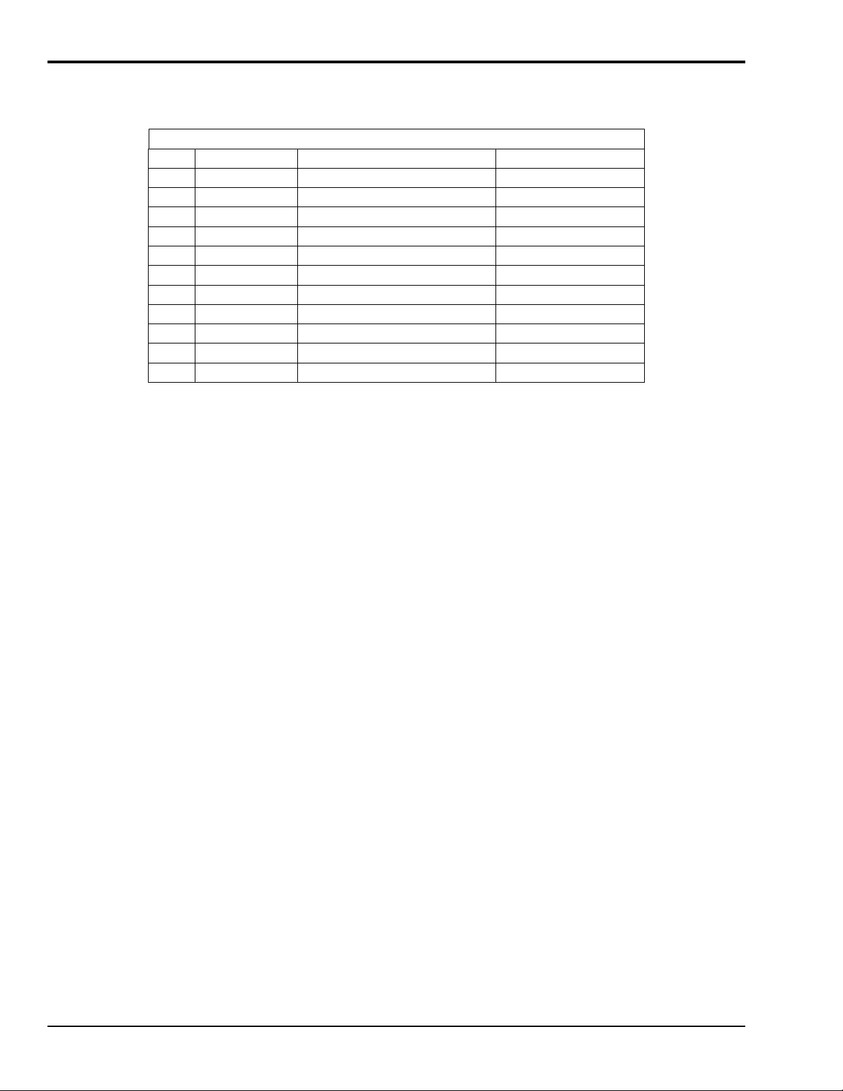
Product Specifications
Accuracy
Type 25°C 15° & 35°C 5° & 45°C
J
K
E
T
S
R
B
G
C
D
N
Cold junction compensation error is in reference to the temperature of the terminals. For types B and G the
above error applies for measured temperatures above 200ºC only. The cold junction sensor can be
recalibrated at any temperature from 0 to 50ºC to improve the accuracy if it will not be used at 25ºC. The
above table applies only after user calibration of the cold junction.
Cold Junction Temperature Differential
For T21 and T71-TC terminal panels only, the temperature gradient in the air adjacent to the cold junction
plate is attenuated 15 times when AWG #22 gage or smaller thermocouple wire is used. The wires are
bundled together for at least one foot from the cold junction terminals. The error is usually less than 0.1ºC.
0 < 0.25 < 0.6
0 < 0.3 < 0.7
0 < 0.3 < 0.8
0 < 0.4 < 1.2
0 < 0.6 < 1.3
0 < 0.4 < 1.6
0 < 1.0 < 2.0
0 < 0.7 < 1.7
0 < 0.5 < 1.2
0 < 0.6 < 1.8
0 < 0.6 < 1.2
Cold Junction Compensation Error
For the T31, T35, T71-GP, and T71-RTD terminal panels there is no isothermal plate. The cold junction
compensation error consists of the above table plus the difference between the terminal temperature and the
cold junction sensor. This difference can be several degrees.
Thermocouple Calibration Numbers
The T21 and T71-TC terminal panels are marked near the 50-pin connector with a serial number (SN) and
cold junction compensation number (CCAL). The terminal panel was calibrated with a matching analog
input board at the factory. A change in CCAL by 75 changes temperature measurement 1ºC.
For maximum accuracy, the panel should be used with the analog input board with the corresponding serial
number. For boards with more than one terminal panel attached, the T71-TC with the matching serial
number should be used for Channels 1 through 8.
Digital Input/Output
For the Digital I/O Termination on All Terminal Panel Types
•
Each line is individually selected to be an input or output.
•
Inputs are TTL and MOS compatible.
•
TTL outputs are available at the input terminals when an I/O is set to an output (except on T71):
•
Maximum voltage on any terminal with digital isolation modules installed: up to 300 VAC, depending on
module.
On T31 Terminal Panels Only
•
Outputs are high voltage open collector:
Low Level: < 0.4 volts at 2 mA (sink)
High Level: > 2.4 volts at 100 µA (source)
Low Level: 50 mA max, < 0.7 volts at 40 mA (sink)
High Level: 30 volts max, <250 µA (source)
6-10 Introduction to Terminal Panels
11-09--01
DataShuttle and DynaRes
Page 67
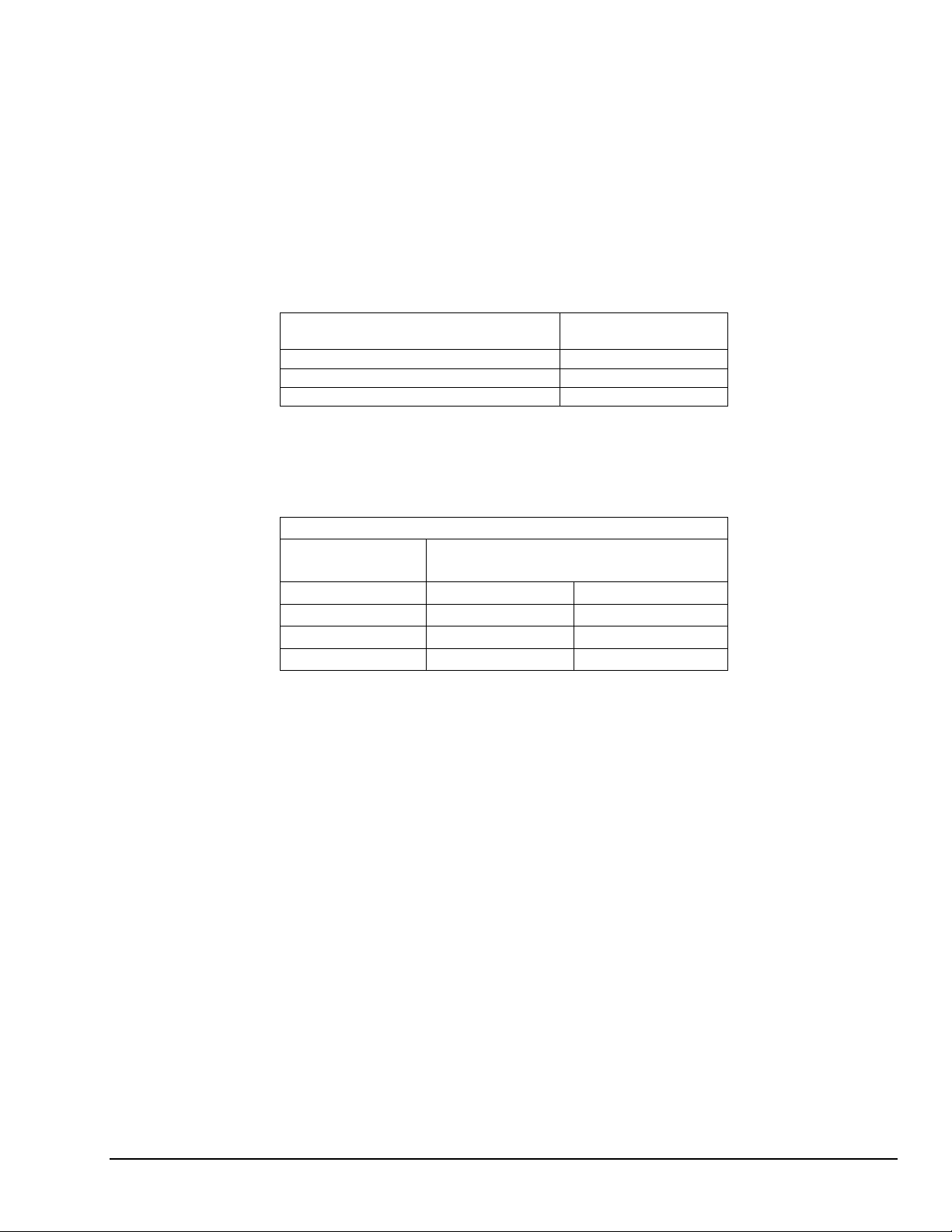
On T71 Terminal Panels Only
•
Outputs are high voltage open collector with pull-up to +5V through LED:
•
· All inputs use Schmitt trigger to improve noise rejection.
General Conditions
Maximum Voltage – 150 volts on any terminal.
Maximum Current – 1 Amp on any terminal.
Auxiliary Power Supplies – The +12 V, +5 V, and -12 V supplies are generated by the computer power
supply. The Vref supply draws its current from the +12V supply.
Low Level: 40 mA max, < 0.7 volts at 30 mA (sink)
High Level: 30 volts max, < 300 µA (source);
can drive > 300µA at 2.5V
Voltage
Maximum Current
(One Board)
+5V 200 mA
+12V 200 mA
-12V 200 mA
Power, except for reference voltage, is supplied directly from the computer power supply. On the T71
terminal panel only, auxiliary supplies are protected by poly switches rated at one Amp. Switches
automatically reset so that nothing is burnt.
Operating Ambient Temperature – 0 to 60º C for the terminal panel, 5 to 90% RH, noncondensing.
Terminal Panel Power Supply Consumption
Voltage Supply Current Consumed by
T31 T71
+5V 50 mA 150 mA
+12V 0 mA 0 mA
-12V 0 mA 0 mA
-5V 0 mA 0 mA
The terminal panel consumes no current from the +5 volt supply if U1 and U2 are removed (except T71).
DataShuttle and DynaRes
11-12-01
Introduction to Terminal Panels 6-11
Page 68

6-12 Introduction to Terminal Panels
11-09--01
DataShuttle and DynaRes
Page 69

Introduction to the ACAO Board 7
Thank you for selecting the ACAO for your project.
Our primary objective is to provide you with data acquisition systems that are easy to install, operate, and
maintain. We also strive to furnish the performance you need at the lowest overall cost. The benefits for you
are increased productivity, data you can count on, and, of course, meeting your budget.
We manufacture the ACAO as an enhancement board that readily mounts in an expansion slot in an IBM
PC, or compatible, computer.
This product’s guaranteed long-term stability makes it ideal both for the laboratory and for harsh industrial
environments.
Using the ACAO together with our graphical interface application software (such as DASYLab
QuickLog™), you can easily and very quickly implement a broad spectrum of research and commercial
tasks, in a wide variety of settings. You can, for example,
•
Ramp, hold, or step analog outputs,
•
Control processes with proportional or on/off control,
•
Set alarm on any digital input,
•
Control devices at preset levels (fans, pumps, heaters, etc.),
•
Control devices from digital input (e. g., from switches or TTL signals), and
•
Control processes unattended.
®
, or
You can use the system interactively, operating controls or modifying your setup while the system is
running.
General Information
Development System
People who decide, to write their own software (rather than using an off-the-shelf application) can employ
the Analog Connection Development System™ hardware driver to address all features of the board from
within a program they design and code for their specific purpose.
Expandability
The ACAO has either two or eight analog output channels and eight digital input/output lines. You can add
one board at a time to your computer, for as many as 15 boards with a total of 120 analog output channels
and 120 digital I/Os. In addition, separate analog input cards may be used with the same software.
Ranges/Units of Output
The ACAO features switch-selectable ranges of 0-10V, 0-5V, or ±5V for voltage output, and 4-20mA for
current output. Self-calibration and self-diagnostics are built into the board to ensure that the output is
always accurate.
Data Presentation
The combination of our hardware and application software (DASYLab or QuickLog PC) enables both the
display of data on the screen, and the logging of data to disk for later analysis.
DataShuttle and DynaRes
11-12-01
Introduction to the ACAO Board 7-1
Page 70

Features and Configurations
Analog Output Channels
Resolution
Data Acquisition Speed
Accuracy
Digital I/O
Terminal Panel
For More Information
For more information about the capabilities of your data acquisition board, please see the “Product
Specifications” in this chapter.
For instructions on controlling the board with our interface software (such as DASYLab or QuickLog PC),
refer to that particular software manual.
The ACAO-12-2 has two output channels, while the ACAO12-8 allows for up to eight analog outputs.
The ACAO is capable of attaining 12 bit resolution (that is,
.024% of signal).
The ACAO is capable of attaining a data acquisition speed of
130 kHz, depending on the software being used. The
maximum data acquisition rate supported by our software for
the ACAO is 1 kHz.
The ACAO is factory-calibrated and very accurate. (If it is
ever necessary, the user can recalibrate the board with
precision using software utilities we provide with every
product.)
The ACAO features 8 digital input/output channels that the
user can configure individually to be input or output.
An available accessory for the ACAO is the T31 generalpurpose terminal panel, which includes terminals for eight
analog outputs and eight digital I/Os.
To learn more about data acquisition, process control in general, and how to use these systems together to
accomplish everyday tasks, consult the Applications chapter.
If you’re creating your own program to address the board for a custom purpose, please see the Analog
Connection Development System manual.
System Requirements
Before installing the board, make sure the computer system fulfills these minimum requirements:
Hardware
•
IBM PC AT (or higher) or -compatible, with at least 640k system RAM.
•
Floppy disk drive, CD-ROM drive and a hard drive.
Software Environment
•
Windows 3.1/95/98/NT.
•
Application software (DASYLab, QuickLog PC, the Analog Connection Windows Development
System, or other compatible proprietary software; please see your software manual for directions for
using it with the DataShuttle). QuickLog for Windows 3.1, 95/98 only.
7-2 Introduction to the ACAO Board
11-12-01
DataShuttle and DynaRes
Page 71

Installing the ACAO 8
Overview
Getting your ACAO data acquisition and process control board up and running is a straightforward process;
you only need to:
•
Verify the board’s switch settings that control board identity and system addressing of these products
•
Physically insert the board into a slot of the personal computer
•
Set the voltage/current switches to suit the measurement you are making
•
Connect a terminal panel to the board
•
Use ACAO CAL to initialize ACAO in driver file. Consult software manual.
•
Load and start up the software to be used for the project.
As the scope of this manual focuses on the ACAO board, this chapter discusses the board’s switch settings,
and the physical insertion of the board.
Please see your terminal panel manual for full instructions regarding its attachment to the ACAO, as well as
for how to connect sensors to the panel.
Guidelines for loading the software, and for starting up, depend on the application program you are going to
use (such as our DASYLab or QuickLog PC, or a package by a third party developer who has our
authorization).
The program you are going to use with the ACAO might even be unique and proprietary, a product of your
organization. (The Analog Connection Windows Development System is a powerful set of utilities making
it possible for software engineers to design and develop their own programs to exploit the ACAO’s many
features.)
In any event, please refer to the software provider’s installation manual, or user guide, for specific
information on how to load and run the particular program.
Troubleshooting – If you have any difficulty getting your board to work, refer to the “Troubleshooting”
section in Chapter 9.
Verifying ACAO Switch Settings
Single Board
When you purchase a data acquisition board new from our company, the product’s switch settings already
are correct to operate a single board with our software (DASYLab, QuickLog, the Analog Connection
Development System, and all others).
This means the factory switch settings are right for the purpose of using only one board, and you can skip
the task of confirming them. You can go directly to the “Physical Board Installation” section on page 8 – 2
in this chapter, and begin to follow the steps there.
Multiple Boards
If you are using more than one board at a time, set the individual boards’ Board Number Switches first
(refer to “Setting the Board Number Switches” on page 8 – 4), then go on to perform the physical
installation.
Otherwise, there’s no reason to be concerned about the board’s switch settings, except in the unlikely event
you encounter a problem in getting your product to operate. (If you experience a problem, refer to
“Troubleshooting,” in Chapter 9).
DataShuttle and DynaRes
11-12-01
Installing the ACAO 8-1
Page 72

Illustration of ACAO Data Acquisition Board, Showing Physical Installation
Previously In Use
If, on the other hand, your board has been in use previously in another computer, or if your company uses
its own proprietary software, the present switch positions might differ from the factory settings.
If your company uses such a program, making changes to factory switch settings might be necessary to
accommodate it. Please consult the administrator of your internal system, or the provider of third party
software, to determine their recommendations for any unusual switch setting.
To check and restore the factory values, please read “Setting the Board Number Switches” on 8–4 in this
chapter.
Physical Board Installation
Installation very simply consists of inserting the board into an open peripheral (expansion) slot inside your
computer.
(There are, for example, five available slots in the IBM PC, and eight in the IBM XT or AT. IBM and
other companies sell expansion chassis that can accept even more analog cards. Our software supports as
many as 15 boards at one time.)
Terminal Panel Connections
When using a terminal panel with the ACAO you are going to be using a single ribbon cable from the
terminal panel. This cable plugs into a 50-pin connector at the back panel of the ACAO and, at its far end,
plugs into a 50-pin connector at the terminal panel.
(Refer to the illustration on page 8 – 2; always check to confirm that the attachment of the cables is
according to the diagram.)
Each 50-pin cable connector has a key on one side that mates with a socket on the device; be sure to
observe polarity when attaching.
8-2 Installing the ACAO
11-12-01
DataShuttle and DynaRes
Page 73

Physical Installation
To Install the ACAO Board
1. TURN THE COMPUTER OFF! Never remove the cover of the computer without first turning the
power switch to the “off” position.
2. Open the Computer Remove the cover of the computer. (If appropriate, refer to your computer’s
manual for more information about removing the cover and installing enhancement boards.)
3. Ground Yourself While holding the board, before installing it, touch the metal chassis of the
computer to discharge any static electricity that might be on the surface of your body.
This is important, as static electricity can damage electronic parts. (Likewise, if you ever remove the
board from the computer, always store it in its protective shipping bag.)
4. Remove the Dust Cover At the back panel of the computer, unscrew and remove the narrow dust
cover plate that is directly behind the expansion slot you want to use. (Keep this screw handy.)
5. Insert the Board. Push the edge of the ACAO board having “gold fingers” down and into the
expansion slot (socket) on the chassis so that the contacts align with the socket, then plug it in by
pushing the board straight down.
Fasten the Board to the Chassis Install the “left over” screw from step 4. Place it in the original
6.
hole, through the ACAO board’s bracket, so that it fastens the top of the bracket to the computer’s
back panel.
7. Connect the Cable to Board and Terminal Pane. Plug the cable into the data acquisition board, and
the connector on its far end into the socket on the terminal panel (please refer to your terminal panel’s
manual, if you are unsure about the correct position).
&$87,21
Incorrect installation of these cables can damage the data acquisition board or the
terminal panel. If you are uncertain about proper placement, please see “Terminal
Panel Connections” at the beginning of this discussion, and inspect the diagrams on
page 8-2 and 9-1.)
Setting the Voltage/Current Switches
The analog output channels of the ACAO (two on the ACAO-12-2 and eight on the ACAO-12-8) can be set
to output in either voltage or current. There are five possible range settings – four voltage and one current –
for each channel. These voltage/current ranges are set with series of switches on the hardware.
Setting the Switches
To Set the Voltage/Current Switches
1. Locate the Switches With the cover of your computer removed, examine the illustration on page 8 – 2
in this chapter and find the “Voltage/Current Switches” and “V/C Range Switches” on the ACAO.
On the printed circuit board itself, the Voltage/Current is a single switch labeled “V/C”. The V/C
Range is of a block of four DIP switches labeled “Range.”
Note that there are three switches for each analog output channel: one large V/C Switch (labeled V/C1
for Channel One,V/C2 for Channel Two, etc.) to set the output for voltage or current and two small
DIP switches to set the voltage range.
2. Set the V/C Switches
For voltage output, you must turn the V/C Switch up; leave it down for a current output.
Set the V/C Switch for each channel accordingly.
3. Set the V/C Ranges for each channel
the same switch module. Switches 1 and 2 select the ranges for Channel One, while 3 and 4 set the
ranges for Channel Two.
Determine whether the output for each channel is to be a voltage or current.
Note that the range switches for Channels One and Two are on
DataShuttle and DynaRes
11-12-01
Installing the ACAO 8-3
Page 74
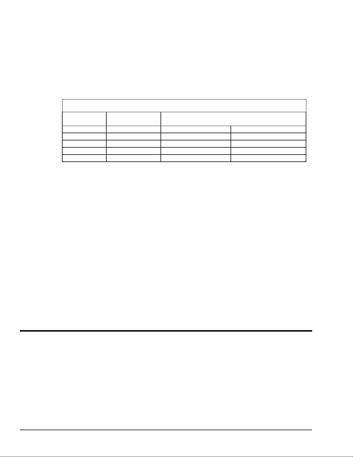
(For ACAO-12-8 boards, Channels Three and Four are paired similarly, as are Channels Five and Six
and Seven and Eight.)
The first range switch for each channel (Switch 1 or 3) selects unipolar or bipolar voltage outputs.
Down selects unipolar; up will output bipolar.
The second range switch (Switch 2 or 4) will determine whether the output will be 5 or 10 Volts. An
up setting selects 5 volts; down is 10 volts.
Note that the range switches do not effect current outputs. If you set a channel for current, it will
automatically output in the 4-20mA range.
See the tables below for detailed V/C switch settings.
V/C Switch Settings for Analog Output Channels
Range V/C Switch Position
1
V/C Range Switch Positions2
Switch 1/3 Switch 2/4
0 to 10V U D D
0 to 5V U D U
± 5V U U U
± 10V* U U D
4 to 20mA D ––
1. U = Up D = Down
2. Switches 1 and 3 set the voltage ranges for Channels 1, 3, 5 and 7. Switches 2 and 4 set the ranges for
Channels 2, 4, 6 and 8.
* Selecting the ± 10V range is an error condition. This range can be used, but the output is not in ± 10V.
Output ranges from -10V at 20% to +10V at 100% of full scale. It does not go below approximately -11V at
16%.
Next Steps
Single Board Usage – If you intend to run with a single data acquisition board in your system, you are now
ready to install your application software.
Multiple Board Usage – If you are going to use more than one data acquisition board, now it’s time to set
each board’s Board Number Switches to an unique number. Follow the steps in the “Setting the Board
Number Switches” section in this chapter on page 8 – 4.
Installing the Software – For information on loading and configuring DASYLab or QuickLog PC please
refer to the user guide for that application package.
Installing the Terminal Panels – To learn how to connect experiments to the terminal panel see your
terminal panel chapter, or the Applications chapter (which discusses data acquisition and control in general
and provides examples of uses for the products).
ACAOCAL must be used to initialize driver file.
Setting the Board Number Switches
Multiple Boards
When you are using multiple boards in your installation, each board needs to have an identity for the
software to recognize it as an “individual.”
The Board Number Switches on a board accomplish this, as they enable you to set an identifying number
for the board.
8-4 Installing the ACAO
11-12-01
DataShuttle and DynaRes
Page 75

This number determines, among other things, the sequence in which the software reads multiple boards
(application programs can address as many as 15 boards).
When using more than one of our product in your installation, every board’s Board Number Switches need
to have a different number setting. All settings are to be in number sequence (1, 2, 3, for example, if you
are using three boards). Set the address and interrupt on all boards to the same settings
Single Board
If your system includes just a single data acquisition board, then you don’t need to be concerned with the
Board Number Switches.
When your ACAO leaves our manufacturing facility, the Board Number switches are set to 1. We
recommend this setting for most purposes when you are using only one board in your installation.
Disabling Board
If you want to disable the board, for any reason, set its Board Number Switches to 0. (This is handy if you
want to use fewer boards for a while: that way you don’t have to remove them from the computer.)
Setting the Switch
To Set the Board Number Switches
1. Locate the Switches With the cover of your computer removed, examine the illustration on page
8 – 2 in this chapter and find the “Board Number Switches” on the ACAO.
On the printed circuit board itself, these are located within a block of eight DIP switches; switches 5
through 8 represent the Board Number.
2. Make the Setting Note that the four switches have 16 possible setting combinations.
Determine which is to be the First Board. (This is easy, if it is the sole board.) Then set the switches for
Board Number 1. (See the table below for board number settings.)
The software interprets Board 1 to use system installation digital I/O channels 1- 8 and analog output
channels 1 through 8 (if it’s an ACAO-12-8), or system installation analog output channels 1 through 2 (if
it’s an ACAO-12-2).
Determine which is to be the Second Board, then set the switches for Board Number 2.
The program then recognizes Board 2 to use system installation digital I/O channels 9 - 16 and analog
output channels 9 to 16 (for an ACAO-12-8) or 3 - 4 (for an ACAO-12-2).
3. Set All Switches Continue to set the switches for all installed boards to unique numerical values in an
unbroken sequence.
(As various models of our boards use different kinds of switches, please see their owner’ s manuals for an
explanation of how to set switches.)
DataShuttle and DynaRes
11-12-01
Installing the ACAO 8-5
Page 76

ACAO Board Number Switch Settings
Board
Number
0 (disabled) D D D D
1 U D D D
2 D U D D
3 U U D D
4 D D U D
5 U D U D
6 D U U D
7 U U U D
8 D D D U
9 U D D U
10 D U D U
11 U U D U
12 D D U U
13 U D U U
14 D U U U
15 U U U U
* U = Up D = Down
Setting the Base Address
Switch Positions*
5 6 7 8
The Base Address determines the logical system address where the personal computer expects to find all
data acquisition boards. Base Addresses must be the same on all boards.
The factory setting for all of our ACAO boards is B00H (in hexadecimal format). If you also have analog
input boards installed in your system, note that that they use the 300H base address. The two underlined
digits must be the same for all installed boards: B00H for ACAO and 300
refer to the individual boards’ owner’ s manuals for further instructions.)
It is rarely necessary, but if you have difficulty getting the board to work, you can change these switches to
values different from the factory settings. (Another device in your PC, for example, might be trying to use
the same Base Address.)
Indications of this are: if the program reports it cannot find your board, or if it reports fewer boards than
you really have, or if another board starts to work improperly after you install the ACAO.
These problems indicate interference with another board using the same base address as the ACAO product.
Remedy the problem by changing the switches of all ACAO boards to an address that has no conflict.
Setting ACAO Base Address
To Set the Base Address
1. Locate the Address Switches Remove the cover of your computer over the data acquisition board, and
find the location of the Base Address switches. Refer to the board illustration on page 8 – 2 in this chapter
and find “Base Address Switches” on the ACAO diagram.
On the printed circuit board itself, these are located within a block of eight DIP switches; switches 1
through 4 represent the base address.
H for analog input boards. (Please
(NOTE: Depending on the space available in your installation, it might be necessary to remove the board to
reach the Base Address Switches. If so, please follow the same precautions as in “Physical Installation” on
page 8 – 2 in this chapter.)
8-6 Installing the ACAO
11-12-01
DataShuttle and DynaRes
Page 77
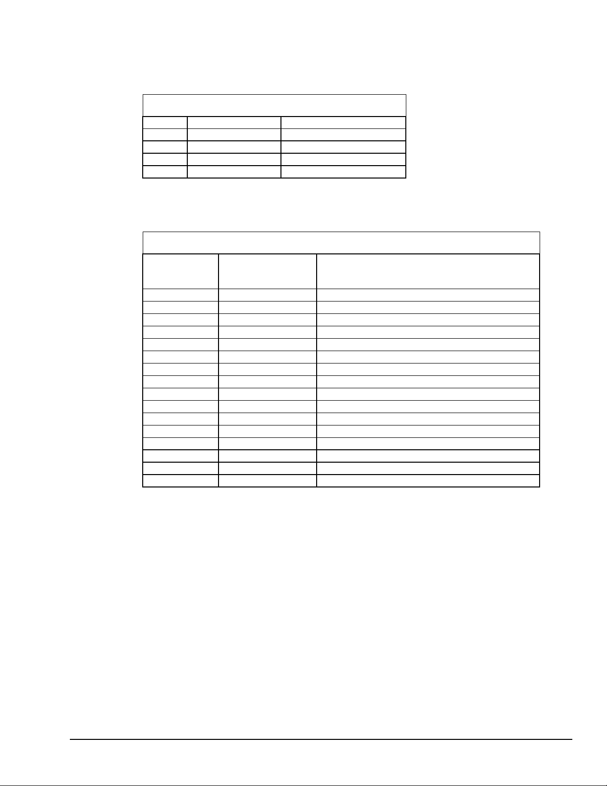
2. Change the Setting 300H is the normal base address. It consists of all four DIP switches being in the
“down” position (when the board is sitting in the computer’s expansion slot).
The DIP switches have the labels “1” through “4.” Sliding a switch to the “up” position adds a value to
B00H:
ACAO Base Address Switch Additive* Values
Switch Position To 300H Add
1 Up 10H
2 Up 20H
3 Up 40H
4 Up 80H
* As the switches are additive, your sliding Switches 1 and 4 up, for example, is going to add 10H and 80H
to the B00H, equalling B90H.
Base Address Settings
Possible ACAO Base
Value Switch Positions*
Comments
1 2 3 4
B00H D D D D Factory setting
B10H U D D D B20H D U D D May interfere with hard disk drive
B30H U U D D B40H D D U D Recommended alternative
B50H U D U D B60H D U U D B70H U U U D May interfere with parallel printer
B80H D D D U -
B90H U D D U BA0H D U D U BB0H U U D U BC0H D D U U BD0H U D U U May interfere with graphics adaptor
BE0H D U U U -
BF0H U U U U May interfere with floppy disk drive
* U = Up D = Down
DataShuttle and DynaRes
11-12-01
Installing the ACAO 8-7
Page 78

8-8 Installing the ACAO
11-12-01
DataShuttle and DynaRes
Page 79
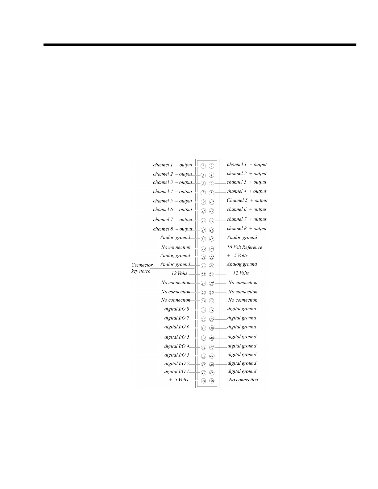
ACAO Analog Output & Control Board Technical Notes 9
Overview
Although operations in this chapter are seldom necessary during everyday data acquisition, you might want
to refer to them at certain times during operation of the ACAO. They are
•
Pinouts (at the board’s connectors, in the event you want to connect analog or digital signals directly,
without using a terminal panel; please refer below);
•
Block diagram of the ACAO showing on-board processing (please see page 9 – 2);
•
Recalibration of all ACAO on-board references to bring the accuracy of the product to factory
specifications (see page 9 – 2);
•
Editing calibration files to accommodate changes to your installation, or to restore missing files
(on page 9 – 3),
•
Troubleshooting: some possible problems and solutions after installing, and during operation of the
ACAO (beginning at page 9 – 6).
DataShuttle and DynaRes
Board Pinouts for the ACAO
11-13-01
ACAO Analog Output & Control Board Technical Notes 9-1
Page 80

Recalibration
Your ACAO uses an exclusive calibration technology to achieve great stability, requiring no adjustment for
years. (As a reflection of this, we guarantee the factory tolerances for two years from the date of purchase.)
Factory Methods
Instead of employing adjustment potentiometers to calibrate the board, our technicians test and calibrate
each ACAO after assembly. They then enter that board’s unique calibration number values into a disk file
that you receive with the product (CALOUT.DAT, for analog output channels; we also print the same
numbers on a label on the back of the board itself).
Whenever you use our software with the board thereafter, the programs read the factory’s calibration
numbers from the disk file, and automatically make minor compensations for real-world conditions
(for instance, high external temperatures that marginally affect calibration).
Recalibration
Under normal conditions, no full recalibration of the ACAO is necessary.
(If you ever suspect that your ACAO is out of tolerance, please call Technical Support for advice.
If it requires recalibration, we can perform the work for you at our facility using the same high accuracy test
equipment we use during the manufacturing quality assurance process.)
Only if your organization is proficient in such techniques, and only if you have the necessary equipment,
do we encourage you to proceed with recalibration (and please contact our Technical Support Department
for guidelines).
Block Diagram of the ACAO (All Models)
For most customers, we recommend returning the board to our Technical Services Department.
9-2 ACAO Analog Output & Control Board Technical Notes
11-13-01
DataShuttle and DynaRes
Page 81
Editing Calibration Files
Depending on your usage of the ACAO, your work might require a more common involvement with
calibration: modifying values in the calibration file on disk.
This can be essential to accommodate occasional changes in your data acquisition setup.
It’s necessary to edit calibration numbers (using ACAOCAL.EXE, the software utility we distribute with the
ACAO, on the QuickLog PC disk) whenever you
•
Reconstruct CALOUT.DAT if this disk file, which holds factory calibration numbers, is lost
(the software tries to read these files upon startup); or
•
Change the quantity of boards in your installation; that is, when you add data acquisition boards to,
or remove them from your computer system.
CALOUT.DAT
The CALOUT.DAT file maintains analog output channel calibration figures for all ACAO boards in the
installation.
CALOUT.DAT is a simple text file containing lines of numbers, or values.
(Another calibration file, CALIB.DAT, contains the analog input channel numbers for all Analog
Connection boards in the installation, and their thermocouple terminal panels. For more information
on CALIB.DAT, see the owner’s manual for any of the Analog Connection boards).
(Regarding DataShuttle: If your installation also includes any of these products, remember that they handle
calibration values differently from the ACAO or Analog Connection boards. Their calibration figures reside
on-board, in Electrically Erasable Programmable Read Only Memory – EEPROM – chips, rather than
in disk files. As a result, their calibration numbers do not appear in either CALOUT.DAT or CALIB.DAT).
Editcal Utility
EDITCAL.EXE (or EDITCAL, for short) is the utility program that simplifies the modification of values
in CALOUT.DAT.
(Instructions for using the program are on page 9 – 5 in this manual; but please continue to read this
discussion, which describes the format of the calibration file, before starting. Also note that it is possible,
although more difficult, to modify numbers in the disk calibration files with a text editor. We recommend
using EDITCAL.)
If a calibration file’s numbers are inaccurate or missing, this means the calibration
of the cards is going to be in error. When you edit these files, take care to enter the
numbers accurately.
Reconstructing Calibration Files
Reconstructing CALOUT.DAT – EDITCAL provides the capacity to reconstruct the calibration file for
ACAO boards if the file happens to be lost entirely.
(If you still have the original distribution disk you can, of course, restore the original factory calibration
numbers from disk).
As the CAL NO label on every ACAO board shows that individual board’s values, it is a straightforward
task to enter the figures into new calibration disk files through the use of EDITCAL. (The CAL NO label
can be found on the back of the ACAO board; the calibration values are listed right after the serial number.)
&$87,21
DataShuttle and DynaRes
11-13-01
ACAO Analog Output & Control Board Technical Notes 9-3
Page 82

Multiple Boards/Panels
Changing the Quantity of Boards – A single CALOUT.DAT file maintains calibration numbers for all
ACAO boards in your system.
When adding an additional ACAO board to the computer installation, it is essential to use EDITCAL
to “merge” its numbers into the existing calibration disk files.
In like manner, if you remove an ACAO from the system, you need to run EDITCAL, removing that
device’s calibration numbers from the file.
Calibration File Format
Analog Output Calibration File
The file CALOUT.DAT contains analog output channel calibration numbers for all ACAO boards.
CALIB.DAT Format
–
The file CALOUT.DAT looks like this:
Content of CALIB.DAT
LINE DATA MEANING
1ANALOG
OUTPUT
CALIBRATION
HEADER
20
3
4
(and
so on)
GROUP A
n
n
(and
so on)
GROUP B
n
n
(and
so on)
GROUP C
* If your present CALOUT.DAT file is unusable, find WCAL, XCAL, YCAL, and ZCAL numbers
1000,1,2,3,4
1001,1,2,3,4
(this group continues
for as many boards
in your installation
that have analog
output channels)
# RANGES
01,23,11,20
12,03,21,02
(this group continues
for as many boards
in your installation
that have analog
output channels)
@ CAL VALUES
8,36,42,32,40,40,34,
35,38
8,22,23,24,25,26,27,2
8,29
(this group continues
for as many boards
in your installa tion
that have analog
output channels)
on your board’s CAL NO label, and enter the values according to the format in this table
Analog output board 1’s serial number, then its WCAL,
XCAL, YCAL, ZCAL values*; next, analog output
board 2’s serial number, and its WCAL, XCAL,
YCAL, ZCAL values*, et al
After the #: Range settings for each and every analog
output channel on board 1; next, range settings for each
and every analog output channel on board 2, et al
After the @: cal values the number of AO channels,
fol lowed by calibration values for each analog output
channel on board 1; next, calibration val ues for each
analog output channel on board 2, et al
(identifier)
9-4 ACAO Analog Output & Control Board Technical Notes
11-13-01
DataShuttle and DynaRes
Page 83

CALOUT.DAT Notes
The third line in the file has the serial number followed by WCAL, XCAL, YCAL, and ZCAL for the
first analog output card.
WCAL, XCAL, YCAL, and ZCAL are the gain calibration numbers for analog output channels for Analog
Connection family products. They correspond to the 0-5V, 0-10V, ±5V, and 4-20mA ranges, respectively.
A second analog output card has its serial number and calibration numbers on the next line, and so on.
Following the “# ranges” sign are range settings. (These ordinarily result from calibrations of the ACAO
when you start up the Analog Connection programs.)
Use ACAOCAL to read board settings and to write settings to STIDRV.INI
Following the “@” sign are the fine tuning calibration values that result from a recalculation taking place
every time you use Analog Connection software. (There is no need to put numbers here. As with the range
settings, the software is going to update them.) The values are in sequence, one for each channel,
and one line for each card.
Reconstructing A Lost Calibration File
In the event the calibration file CALOUT.DAT becomes corrupt, or is missing, it’s first necessary to
reconstruct a replacement text file before running EDITCAL. Use any text editor to create a new file,
giving it the appropriate name (CALOUT.DAT).
Enter this text on the first line in the file:
ANALOG OUTPUT CALIBRATION
and then press [ENTER] ten times, to establish a total of 11 lines in the file. Save the file to the same
subdirectory as your other applications programs.
Now you can use EDITCAL to read and restore the calibration numbers by using its UPDATE menu
selection (please see “Using EDITCAL”).
Using EDITCAL
Although the preceding tables might give the impression that editing calibration files is highly complex, the
EDITCAL utility makes the task relatively easy.
Starting EDITCAL
Make sure the EDITCAL.EXE program file is in the same sub-directory as the application programs and the
CALOUT.DAT file.
Load the EDITCAL.EXE program from the keyboard:
To Start Up EDITCAL.EXE
At the DOS prompt, enter EDITCAL, then press the [ENTER] key. (This invokes the utility.)
DataShuttle and DynaRes
11-13-01
ACAO Analog Output & Control Board Technical Notes 9-5
Page 84

EDITCAL Selections
To Select a Function
Once EDITCAL is up and running you can use the arrow keys to navigate back and forth
among the following menu selections:
Data Files: To merge calibration files supplied from the factory into a single file for
systems that have multiple units, or to update existing calibration files.
AC EEPROM: To view or modify calibration data on Analog Connection units that
have non-volatile on-unit EEPROMS.
DS EEPROM: To view and/or modify the calibration numbers of DataShuttle
EEPROMs, or to perform an analog calibration
QUIT: Ends the EDITCAL session.
4. Move the arrow keys until DS EEPROM is flashing.
5. Press [ENTER].
6. Proceed according to the on-screen instructions that appear after making your selection.
At any time during your use of EDITCAL, you can press the [F1] key to display help-
text regarding a highlighted field.
Troubleshooting: Installation
If you experience difficulty in getting your data acquisition board up and running, please check to see that
the installation is according to the descriptions in Chapter 8.
If the software reports a board failure, or that it cannot find a board, then try these remedies:
1. Confirm that the board is seated properly in the PC expansion slot (reseat it, if necessary; see the
illustration on page 8 – 2).
2. Verify the Board Number Switches are not set to “0.” (Refer to page 8 – 4).
3. Use a different Base Address. It is possible that another device in your installation is trying to use the
same Base Address (please see the explanation on page 8 – 6).
4. If there is more than one data acquisition board in your installation, make sure they all have the same
Base Address and interrupts, sequential Board Numbers, starting with 1.
5. Install the board in another open slot in the PC (follow the instructions on page 8 – 2).
6. Remove other devices from expansion slots in your PC to check whether they are conflicting with
your data acquisition board.
7. If possible, install the board in another computer to verify its correct operation.
8. Verify that the software is up to date (a version compatible with the board you are using. Contact us,
or your software provider).
9. Remove other terminate and stay resident (TSR) programs from your system’s AUTOEXEC.BAT
file, temporarily.
9-6 ACAO Analog Output & Control Board Technical Notes
11-13-01
DataShuttle and DynaRes
Page 85

Troubleshooting: Operation
Operating Qs And As
1. Problem: Initial startup of software; can see ACAO but software says can’t connect to ACAO board
number.
Action: Run ACAOCAL to initialize ACAO in STIDRV.INI file.
Proper instillation will cure this.
2. Problem: After changing the switch settings on my board from voltage to current or to different
voltage ranges, my outputs are inaccurate.
Action: If you change any switch settings on the board, you must update the software as well. To do
so, go back to DOS and rerun the GFIND command with the -c parameter.
3. Problem: I get a “Reference Error” message when I run GFIND.
Action: This error occurs when the traces labeled F1 and F2 (found on the bottom right of the board)
are burnt. In these cases, you must replace the burnt traces with a 1Amp maximum resistor fuse.
4. Problem: At start-up, I get a “Cannot Calibrate – check for short” message.
Action: This error message occurs primarily when the channel in question is set to voltage. During
start-up, calibration is performed on the board if the -c parameter is used with the GFIND command.
Voltage calibration can only be completed if nothing is connected to the terminal panel. If there is a
connection, you will usually receive this error.
To correct this error, you can remove any connections to the terminal panel. Alternatively, you can
rerun the GFIND command without the -c parameter.
5. Problem: At start-up, I get a “Cannot Calibrate – check for open” message.
Action: This error message occurs primarily when the channel in question is set to current. During
start-up, calibration is performed on the board if the -c parameter is used with the GFIND command.
For current calibration to take place, the +12V terminal must be connected to the +ve terminal of the
channel in question. If this connection is not made, you will usually receive this error.
Ensuring this terminal connection will usually get rid of this message. Alternatively, you can rerun the
GFIND command without the -c parameter.
6. Problem: My board used to work, but now the software cannot find it, or reports an error.
Action: Check to make sure the Board Number Switches are not set to “0.”
7. Problem: When my software starts, the outputs of the board momentarily go to full scale.
Action: If the GFIND program is run with the -c parameter, the ACAO board will be calibrated by
sending full scale outputs. Removing the -c will prevent this from happening at a slight loss of
accuracy.
If you Need Customer Support
What to do before calling technical support, to help us serve you better:
1. Have the part numbers of your boards and terminal panels ready.
2. Have the type and version number of the software you’re using.
3. Have your computer’s type, model, and the version of the operating system.
DataShuttle and DynaRes
11-13-01
ACAO Analog Output & Control Board Technical Notes 9-7
Page 86

Product Specifications
Analog Outputs
The ACAO-12-2 features two analog outputs; the ACAO-12-8 includes eight analog output channels.
Analog Output Ranges
The ACAO can output either voltage or current. Selectable voltage ranges include 0–5V, 0–10V, and ±5V;
current is output in the 4-20mA range only.
Resolution
The ACAO can operate with resolution of up to 12 bits.
Speed
The ACAO has a maximum output rate of 130kHz on a standard IBM PC running at 4.77MHz (rates are
somewhat faster in faster computers).
For the multi-channel output rate, divide the maximum 130kHz rate by the number of channels using an
assembly language program.
Maximum/Minimum Output
In Voltage Output Mode
•
Output Current: ±15mA minimum
•
Output Protection: May be shorted to any voltage between +12 and -12V
•
Output Impedance: <0.1
Ω
Stability
In Current Output Mode
•
Maximum Output Voltage: +50V
•
Minimum Output Voltage: +2.6V
•
Output may be shorted to any voltage between 0 and +50 volts
Accuracy ACAO General Conditions Accuracy
Range Absolute Accuracy Maximum Offset
0 to 10V 0.02% 0.01%
0 to 5V 0.02% 0.02%
±5V 0.07% 0.06%
4 to 20 mA 0.15% 0.04%
Relative accuracy for all ranges is a maximum of 0.01%.
There is a 0.01% maximum linearity for all ranges, guaranteed monotonic. The differential linearity is a
maximum of 0.01%.
In Voltage Output Mode
•
Temperature Drift:
With self-calibration is 0.002% / ºC maximum
Without self calibration is 0.008% / ºC maximum
•
Response time to 0.01% accuracy:
Small step is 2.5µs
5V step is 20µs
10V step is 35µs
9-8 ACAO Analog Output & Control Board Technical Notes
11-13-01
DataShuttle and DynaRes
Page 87

In Current Output Mode
•
Temperature Drift:
With self-calibration is 0.006% / ºC maximum
Without self calibration is 0.015% / ºC maximum
•
Response time to 0.01% accuracy:
Small step is 2.5µs
16mA step is 10µs
Digital I/O Channels
The ACAO has eight digital I/O lines, with each line individually selectable as input or output. These
channels are TTL- and MOS- compatible as they come out of the board.
Their outputs sinks are open collector and are 3 milliAmperes; as inputs they draw 5 milliAmperes when
low. (Please see the specifications in your terminal panel owner’s manual for open collector output.)
Auxiliary Power Output
Auxiliary Power Output For The ACAO
Voltage Maximum Current
+10V 15mA
+12V 200mA
+5V 100mA
-12V 200mA
Power, except for 10 volts, is supplied directly from the computer power supply. The +10V supply draws its
current from the +12V supply.
10 Volt Reference
•
Output Current: 15mA maximum
•
Initial Accuracy: 9.9 to 10.1 volts
•
Temperature Drift: 0.0008% / ºC maximum
•
Drift with time: 0.003% / 1000 hours
General Conditions
General Specifications of the ACAO
•
Operating Temperature Ambient: 0 to 50ºC
•
Board Dimensions:
•
The supply current consumed by the ACAO varies according to number of analog output channels as
well as voltage settings. (See table below for variations.)
The ACAO-12-2 is 4.2” x 5.25” (11.8 x 14.7 cm)
The ACAO-12-8 is 4.2” x 9.5” (11.8 x 14.7 cm)
ACAO Power Consumption
Voltage Supply Current Consumed by
ACAO-12-2: ACAO-12-8:
+5V 320mA 320mA
+12V 40mA 65mA
-12V 15mA 15mA
Total 2.6 Watts 2.9 Watts
DataShuttle and DynaRes
11-13-01
ACAO Analog Output & Control Board Technical Notes 9-9
Page 88

9-10 ACAO Analog Output & Control Board Technical Notes
11-13-01
DataShuttle and DynaRes
Page 89

QuickLog Introduction 10
General Information
Our primary objective is to provide you with data acquisition systems that are easy to install, operate, and
maintain. We also strive to provide the performance and versatility you need at the lowest overall cost. The
benefits for you are increased productivity, data you can count on, and, of course, meeting your cost and
time budgets.
QuickLog for Windows (QuickLog) is a menu-driven data acquisition software application that is supplied
with all of our data acquisition hardware products. It has an easy-to-use tabular interface, which brings
simplicity to the laboratory and industrial environments, allowing you to set up a typical data acquisition
application in less than 30 minutes.
Using QuickLog, together with our plug-in data acquisition boards and/or parallel port DataShuttles, you
can easily and quickly implement a broad spectrum of R&D or industrial tasks, in a variety of settings.
You can, for example,
•
Display data in meters and charts,
•
Automatically linearize thermocouples and RTDs,
•
Monitor processes and experiments,
•
Log data to disk for later analysis,
•
Control devices using digital outputs,
•
Gather data unattended, and
•
Exchange data with other Windows applications via DDE.
This chapter shows how to install the QuickLog software. Please refer to Chapter 11 for instructions on
operation.
What You Need
These are the items necessary to start using QuickLog:
•
This manual
•
The QuickLog disk, and
•
Any of our data acquisition device (connected to your PC according to the Owner’s Manual).
System Requirements
QuickLog works with most Wintel personal computers (PCs with Intel, or Intel-like CPUs, running
Windows) available today. The minimum software and hardware requirements your PC needs to run
QuickLog successfully are listed below. To get the best performance from the software, especially when
more than one Windows application is to be run, we recommend additional hardware resources.
Minimum Requirements
A personal computer with a 386 processor, a standard keyboard, a mouse or similar pointing device, and
•
4 MB memory (RAM),
•
2 MB of free hard disk space
•
3.5" diskette drive,
•
A monitor and a VGA display adapter supported by Windows,
•
One parallel interface (Centronics) if using a DataShuttles, and
•
Windows (v3.1or later) or Windows 95/98 (No NT support).
DataShuttle and DynaRes
11-12-01
QuickLog Introduction 10-1
Page 90

Setting Up QuickLog
Make sure that your QuickLog package is complete. In addition to this printed document, it should contain
a floppy disk, the Hardware Installation Manual, and the registration card.
Make sure that there is at least 2 MB of free space on the hard disk on which you intend to install
QuickLog.
Insert the QuickLog disk into the floppy disk drive.
Starting the Installation
For Computers Running Windows 3.x
1. From the File menu in Windows Program Manager, choose Run. The Run dialog box will appear.
2. In the command line, type the drive letter of the drive you are using, followed by a colon and the
QuickLog installation program file name, SETUP. (You may type upper or lowercase letters.) For
example: A:SETUP
3. Press the Enter key. The QuickLog installation program will start.
For Computers Running Windows 95/98
1. Open the Control Panel.
2. Select Add/Delete Programs.
3. Windows 95 will search for the installation disk. Select finish and the QuickLog installation program
will start.
You can exit the installation procedure any time by clicking the Cancel button. However, QuickLog will not
be completely and properly set up.
Setup Summary
You will be asked to specify the drive and the directory where QuickLog is to be installed. The default is
C:/QLFW. You may type a different path, but it must be a valid MS DOS path:
Then choose OK. The installation program will:
•
Check if the specified directory exists, and create it if necessary.
•
Check if there is enough free space on your hard disk. If not, you will be asked to enter another drive or
to cancel setup.
•
Copy all QuickLog program files to the drive and directory.
•
Create a QuickLog program group in the Windows Program Manager. If the group already exists, it
will be opened.
•
Create various program items within that group.
•
Add the command line DEVICE=DRIVE:/DIRECTORY/ DIRECTORY/.../STIDATAQ.386 to the
[386Enh]section of the SYSTEM. INI file to install the virtual device drive needed to communicate
with the hardware.
Completing Setup
Restart Windows so that the changes made to your system can take effect, so that the driver will be loaded.
Drive:/ Directory/Directory
10-2 QuickLog Introduction
11-12-01
DataShuttle and DynaRes
Page 91

Specifications
Meter Display Screens
Types of I/O Supported – Analog In, Analog Out, Digital In, Digital Out, Counter/Timer pulse input,
Counter/Timer frequency input, and Time.
Maximum Number of Data Acquisition Devices – 15
Maximum Number of Channels Per Board – 160. Channel name and/or units may be typed in.
Analog Input Ranges Supported – all that are supported by the data acquisition driver.
Analog Input Resolution Supported – all that are supported by the data acquisition driver.
Analog Output Ranges Supported – all that are supported by the data acquisition driver
Scaling of Any Input Type – linear, y = mX + b.
Outputs (analog or digital) may be changed by typing the value into the digital meter.
Size of Digital Meter Display – selectable height and width.
Number of Digital Meters – selectable from 1 to 100.
Chart Display Screen
Single chart with selectable time scale. Y axis is % of specified range or user entered maximum and
minimum range. Includes the scaling specified in the digital meter display.
Chart is a window that may be sized as desired.
Types of I/O Supported – Analog In, Digital In, Counter/Timer pulse input.
Number of Traces Displayed – 14 maximum.
Logging
Data Type – ASCII characters, tab-delimited.
Maximum Number of Logged Channels – 256
Log Rate – same as sample rate
Types of I/O Supported – Analog In, Digital In, Counter/Timer pulse input.
DDE
Any meters may be linked to another application using DDE.
Inputs can be sent, and outputs can be received, from the other source.
DDE Rate – same as sample rate, or same as rate requested by other application.
General Configuration
The following settings are available for the general configuration of QuickLog:
•
Sample rate: same for all channels, inputs and outputs,
•
Polled or synchronous mode for all types: Analog In, Analog Out, Digital In, Digital Out,
Counter/Timer pulse input, Counter/Timer frequency input,
•
Polled mode: maximum speed is several samples/second,
•
Interrupt mode: maximum speed is several hundred samples/second,
•
Number of input meters,
•
Input meter font size,
•
Log file name, and
•
Number of output meters.
•
Output meter font size.
DataShuttle and DynaRes
11-12-01
QuickLog Introduction 10-3
Page 92

I/O Configuration By Channel
The input and/or output of each channel can be configured using these options:
•
Device (board)
•
Channel
•
Range (AI and AO only)
•
Resolution (AI only)
•
Scale (AI only): y = mx + b where m and b may be entered.
•
Logging: yes/no.
•
Display on chart: yes/no.
Chart Configuration
Charts can be configured according to these available settings:
•
Number of points on time axis (2 to 1000)
•
Number of labels on time axis
•
% of full scale on Y axis (0 to 100)
•
Scaling of Y axis: -1e10 to 1e10
•
Selectable options:
Color for each trace
Line type for each trace
Chart Colors
•
Viewing Style: Color, monochrome, monochrome + symbols
•
Plotting method: Line, Point, Points + Line, Points + Spline, Spline
•
Graph or Table: Graph, Table, Both
•
Grid Lines: Both, Y axis, X axis, None
•
Grid in front
•
UnZoom
•
Font size: Large, Medium, Small
10-4 QuickLog Introduction
11-12-01
DataShuttle and DynaRes
Page 93

Getting Started with QuickLog 11
General Information
QuickLog is entirely menu-driven. You control data acquisition, display, and disk logging by configuring
QuickLog via the pull-down menu system.
QuickLog is based on one display screen of digital meters that are used to display all types of available
inputs, and another screen for all types of available outputs. In addition, it displays input signals on a Y-t
chart, as well as logs these inputs to disk.
You can change the name on each input or output meter to identify it.
When you first launch QuickLog, it searches for hardware devices, first on the ISA bus inside the PC, and
then on all installed printer ports. It then creates Input, Output, and Chart windows that reflect the installed
hardware.
QuickLog runs, and collects and displays input data, as soon as it is launched. It continues to run when you
are configuring the various options. If you load a configuration file that does not match the installed
hardware, it automatically adjusts the configuration file to match the hardware, and displays a warning
message.
This chapter briefly explains the various menus, with a description of their functions. QuickLog also has an
extensive on-line Help facility, which has more information than what is contained here.
File Menu
Edit Menu
Save As Startup
Print Window
Export Chart
Exit
Paste Link
Standard functions include those for creating, loading, and saving
configurations. These are New, Open..., Save, and Save As. Select New to
revert to the default configuration. Other file menu commands and their
functions include:
The Save As Startup command allows you to define your own startup
configuration, using your desired settings.
Print Window immediately prints the active top window, using the default
Windows printer.
Export Chart to the Windows clipboard, a file, or to your printer.
Exit closes the program.
Cut, Copy, Paste, and Delete are standard editing functions.
Paste Link allows you to paste DDE links from another application into an
output meter.
DataShuttle and DynaRes
11-13-01
Getting Started with QuickLog 11-1
Page 94

Options Menu: General
Sample And Log Rate
Mode
Input Meters
Output Meters
You may select the Sample Rate, in Hz, which is the rate of reading and
displaying inputs and logging to disk. The maximum rate depends on the
Mode you have selected, the speed of your PC, and the data acquisition
hardware installed.
The Polled (or Asynchronous) mode samples at the rate set by the
application, and is the slowest data acquisition rate. This mode does not use
interrupts for most data acquisition devices. However, this mode is the
simplest to use.
The Interrupt (or Synchronous) mode samples at a precise rate set by the
driver, and allows much faster sampling. Most data acquisition devices
generate hardware interrupts to pace the driver, and thereby set the rate.
Refer to the on-line help for more information about these modes.
When first launched, QuickLog detects the hardware installed, and creates a
default user interface made up of a table of windows, called Input Meters,
which display the analog, digital, or Counter/Timer values being sampled.
You may change the number of Meters being displayed, as well as the
number of horizontal and vertical Meter windows, using the General
Options menu. Color and font size are also selectable.
You may set up the Output Meters in the same fashion as described above,
if you have a device installed that has analog or digital outputs.
11-2 Getting Started with QuickLog
11-13-01
DataShuttle and DynaRes
Page 95

Options Menu: Inputs
Window Label
This window allows you to define which readings will be displayed in the
Meter window. You may select data acquisition Device 1 through 15, the input
Function...None, Analog In, Digital In, Pulse In, Time, Date (from the PC
clock), and which Channel on that device will be assigned that input function
The first column accepts a typed in label for that Input Meter window, in place
of the default label.
.
Analog Input Range
Resolution
Scale
Log & Chart
When you select Analog In, you may select the input Range from a table that
will depend on the ranges available on the device you have connected to your
PC.
The column Resolution allows selection of A/D resolution, again dependent on
the device connected. Some devices allow for averaging the samples to reduce
noise. Also, Low Noise mode is effective in greatly reducing AC line
interference.
When you click on the radio button Scale = mX + b, a new field opens to allow
you to enter coefficients for a linear scaling of the analog input readings into
engineering units
Log and Chart columns allow you to select whether this channel will be logged
to disk and/or displayed on the Chart. At least one channel must have the Log
box checked to have logging to disk. At least one channel must have the Chart
box checked to have a trace on the chart.
Options Menu: Output Meters
The functions in this menu are similar to the Input Meters Options menu
described above but these selections operate on the output signals: Analog and
Digital.
Options Menu: Chart
This window allows you to customize the appearance of the Y-t Chart display.
All of the parameters are available in one window, as opposed to the function
of the Chart menu described below, where an abbreviated set of attributes are
accessible separately in the menu.
Options Menu: Colors
And Lines
DataShuttle and DynaRes
Chart Colors and Lines can be used to select colors and line types on the chart.
11-13-01
Getting Started with QuickLog 11-3
Page 96

Chart Menu
Unlike the Options menu, these selections do not cause the Chart data to be
erased.
Undo Zoom
Chart Zoom
Other Options The balance of the menu items, Viewing Style, Font Size, Plotting Method,
Run Menu
.
Window Menu
Undo Zoom allows you to cancel a Chart zooming operation; alternatively, use
the keyboard shortcut Ctrl+Z.
Chart Zoom allows you select a region of interest in the data, and expand it to
fill the Chart display window. Place the cursor at one edge of the region of
interest, and hold the left mouse button down. Move the cursor to draw a box
around the region, and release the mouse button. The region will expand to fill
the window. The X and Y scales will also expand to maintain the proper scale.
Grid Lines, Grid in Front, and Graph or Table, are direct menu access to the
same items as in Options, Chart. Refer also to the on-line Help.
To Start the acquisition, press F5; to Stop, press F6. When acquisition is
running, a green Running indicator lights up at the left edge of the menu bar;
when stopped, the indicator turns red
This menu allows you to pull the Input (F9), Output Meter (F11) displays, and
the Y-t Chart (F12) to the foreground of the screen.
Calibration Menu
Calibrate Analog
Inputs
Autocalibrate
Calibrate Analog
Outputs
Change Numbers
Help Menu
Installed Hardware
When you click on this entry, the analog input circuits of all devices are
immediately calibrated against their respective internal precision voltage
references, which compensates for drift and offset.
You may select the interval at which you wish to invoke the above calibration
function.
This selection calibrates analog outputs on some hardware
Note: Outputs are changed from minimum to maximum on all ranges
during calibration.
This utility allows you to perform a complete recalibration of the device. If you
follow the instructions given in the Help file, you can restore the device to the
original factory accuracy. However, please observe the cautionary statement in
the window, and in the Help file.
The Help menu provides on-line help for QuickLog. The on-line help is a
complete guide to the use of QuickLog, with much more information than this
.
manual
Installed Hardware is very helpful when calling our Technical Support people.
The information contained in this window will help speed the answers to your
application and troubleshooting questions
.
11-4 Getting Started with QuickLog
11-13-01
DataShuttle and DynaRes
Page 97

Applications Primer 12
Our primary objective is to provide you with data acquisition systems that are easy to install, operate, and
maintain. We also strive to furnish the performance you need at the lowest overall cost. The benefits for you
are increased productivity, data you can count on, and, of course, meeting your budget.
Part of meeting that objective is contained herein. Because the PC is a general purpose tool for data
acquisition applications, we think it helpful to provide you with information for your specific application.
This Applications Handbook gives you a detailed description of how to use our products to complete a
variety of data acquisition tasks.
Data acquisition is divided into two distinct types: ANALOG and DIGITAL. An example of analog data
acquisition is temperature measurement. An example of digital data acquisition is observing the on/off state
of a conveyor belt. Further, data acquisition usually refers to measurement (input) and control (output).
Also, most data acquisition applications have a combination of inputs and outputs, analog and/or digital.
This Handbook covers all of the most common PC data acquisition applications, as well as a few
uncommon applications. If your particular application is not covered here, and you need further assistance,
please contact our technical support department.
We begin with a few generalities regarding sensor connections, followed by more specific examples for
analog applications in Chapter 13, and digital applications in Chapter 14.
Applications Reference
Almost any type of sensor can be connected to Analog Connection data acquisition equipment. For each
type of sensor, a detailed description of the connections and software setup is given. Sensors that are not
listed may be connected as long as they have a voltage or current output.
Connection Types
Analog Input & Output Applications
•
Thermocouples
•
Strain Gages
•
Current Input
•
High Voltage Dividers
•
RTD’s (resistance temperature detectors)
Digital I/O Applications
•
High Power Optically Isolated Digital Output
•
High Power Optically Isolated Digital Input
•
Low Power Optically Isolated Digital Output
•
Low Power Optically Isolated Digital Input
•
Non-Isolated Digital I/O
•
Pulse Counting
•
Cascaded Counter/Timers
•
Frequency or Rate Measurement
•
Piezoelectric Sensors
•
Audio & Video
•
Voltage Output
•
Current Output
DataShuttle and DynaRes
11-12-01
Applications Primer 12-1
Page 98

Sensor Connections
There are several general topics regarding sensor connections that must first be presented. These are singleended vs. differential connections (for analog input), auxiliary power output and voltage reference, auxiliary
components (sometimes needed to make certain sensors work), and digital line connections.
Single-Ended vs. Differential Connections
This concept refers to how analog input sensor wires connect to the terminal panel. A single-ended input
has only one wire from the sensor connected to each channel. The other wire from the sensor is connected
to a common return for all channels. In this case, the A/D converter measures the voltage difference
between the sensor wire and ground.
A differential connection means that there are two wires from your sensor that are connected to the terminal
panel. Here, the A/D converter measures the voltage difference between the two wires.
When using boards in differential mode, analog inputs connect to the + and – terminals on the terminal
panel. The reading is positive when the + terminal is positive with respect to the negative terminal. The
COM terminal is ground. Often, the COM terminal is connected to the – input with a jumper plate. When
the input voltage already has a ground reference, remove the connection to the COM terminal so that
current won’t flow between the two ground points, creating a voltage drop in the wire (a ground loop).
When using a data acquisition board in single-ended mode (if applicable), analog inputs 1 through 8
connect between the + terminal of channels 1 through 8, respectively, and GND on the terminal panel. The
reading is positive when the + terminal is positive with respect to GND. The reading is negative when the
positive terminal is negative with respect to GND. Channels 9 through 16 connect between the – terminal
of channels 1 through 8 respectively, on the terminal panel and GND.
The reading is positive when the – terminal is positive with respect to GND and the reading is negative
when the – terminal is negative with respect to GND.
Auxiliary Power Output & Voltage Reference
Many sensors, such as RTD’s, thermistors, strain gages, and pressure sensors, need a stable power source
because the output is proportional to the power applied. For this reason, a stable voltage reference is
available in all analog input and output boards (accessed via the terminal panel). Another advantage to the
voltage reference is that it can be used for easy recalibration of analog inputs (see your hardware manual).
All other analog input boards have a 6.6-6.9 Volt reference with a low impedance that can supply 20mA of
current (refer to the hardware manual for specifications). The ACAO-12 (analog output) has a 10 Volt
reference, also with a low impedance that can supply 20mA of current.
Alternatively, you can use the +5 Volt or ±12 Volt lines to provide power for your applications. These
sources, however, are typically noisy,
and may vary, so they do not make good reference voltages. Yet, they
are an excellent source of relatively large amounts of power for sensor electronics.
Auxiliary Components
For some sensors, it is necessary to install auxiliary components. These components provide signal
conditioning and can easily be installed in the terminal panel for convenience.
Installing auxiliary components requires soldering and some familiarity with electronics. Most common
sensors can be connected without the use of auxiliary components.
Refer to the your Terminal Panel manual for more information on installing these components.
Digital Connections
Wires for digital signals connect to either the IN (+) or OUT (–) terminal and GND. Most software
automatically changes each line to be either an input or an output when you use the line.
12-2 Applications Primer
11-12-01
DataShuttle and DynaRes
Page 99

Special Note For Thermocouple Applications
In addition to the thermocouple application instructions given in Chapter 13, Appendix I provides detailed
information on common problems encountered with these sensors, along with specific instructions for solving such problems.
DataShuttle and DynaRes
11-12-01
Applications Primer 12-3
Page 100

12-4 Applications Primer
11-12-01
DataShuttle and DynaRes
 Loading...