

Page 1
DataShuttle, DataShuttle Express,
Reference Notes:
For information regarding signal conditioning, refer to the product’s Application Reference material in your
user’s manual. Refer to hardware sections as needed.
and
DynaRes
Quick Start
Hardware Installation
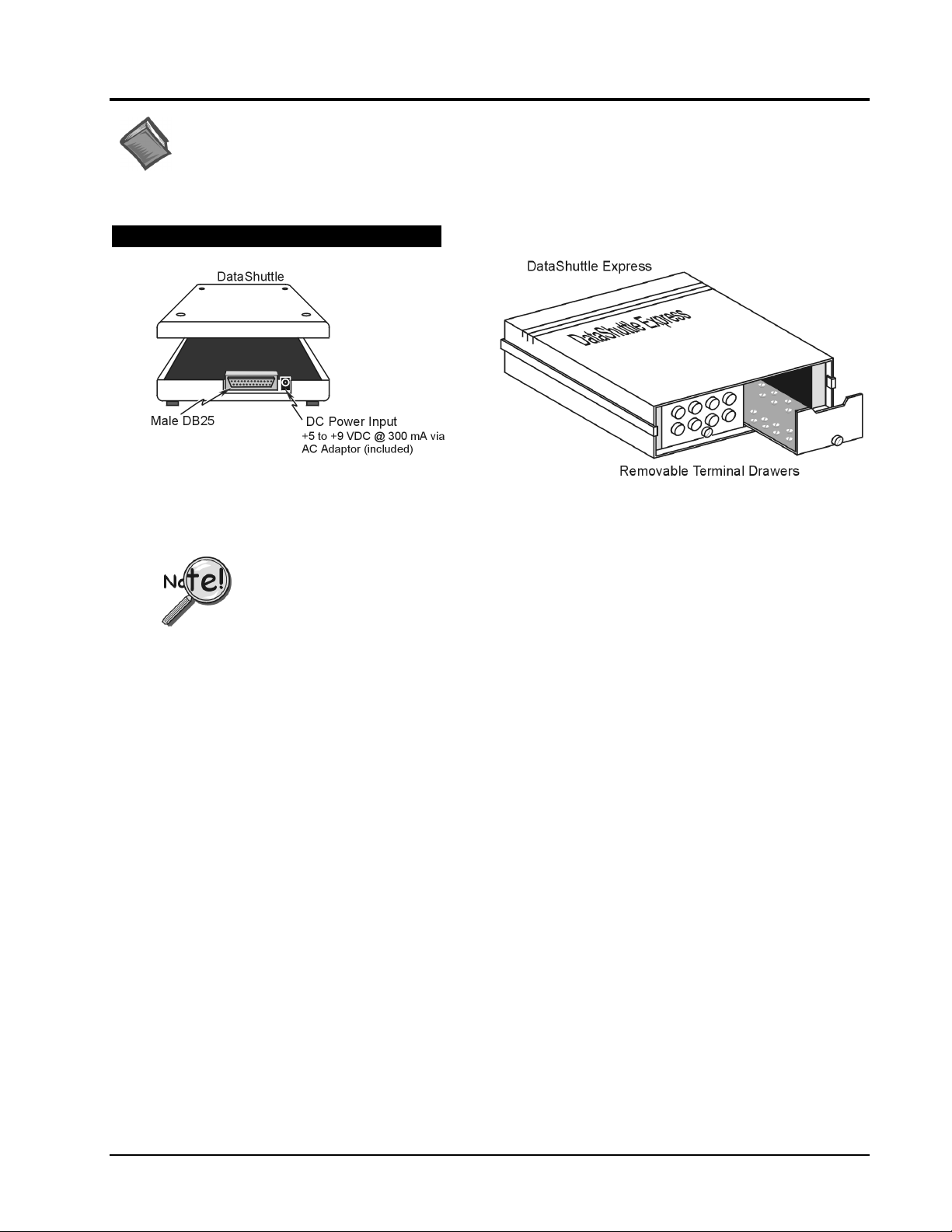
DataShuttle and DataShuttle Express
Both the DataShuttle and DataShuttle Express connect to a computer by cable through a Male DB25 connector.
Both units have a Female DB25 “pass-through” port (not shown in figure).
With exception of additional DataShuttle Express units, DataShuttle Express can not be
•
used in conjunction with any other data acquisition device.
Each DataShuttle Express must be powered from its own, independent power supply.
•
1. Connect the unit’s Male DB25 (parallel input connector) to your computer’s Female DB25 (parallel port).
Use the D13-25 cable (provided).
2. For DataShuttle Express: Lossen thumbscrews and slide the Terminal Drawers out. Note that Terminal
Drawers with external connectors (such as BNCs) can remain in place.
For DataShuttle: Remove the unit’s cover. Note that some models have covers secured with screws,
while others have covers that snap on or off.
3. Connect your application sensors to the unit.
4. For DataShuttle Express: Slide the Terminal Drawers back in place. Tighten thumbscrews.
For DataShuttle: Replace the cover. If applicable, replace and tighten screws (do not over tighten).
5. If you wish to install additional DataShuttle or DataShuttle Express units, connect the new unit’s
Male DB25 port to the Female DB25 (pass through port) of the last unit in the series.
Use the provided cable.
•
To print from the same parallel port, connect the printer cable to the pass through port of the last unit in
the series. For DataShuttle, printing can only occur if an acquisition is not in progress.
•
For DataShuttle Express, printing can only occur if DASYLab or Quick Log (or other Windows based
application) is closed.
Connect the AC adapter to the power connector on the unit. Plug an appropriate power cord into the
6.
adapter, then connect the adaptor to an AC power line.
7. Install and run the application software (DASYLab or Quick Log) as instructed on page 3 of this document.
1052-0940, rev. 1.0
DynaRes, Data Shuttle, & DataShuttle Express - Quick Start
June 1999
1
Page 2
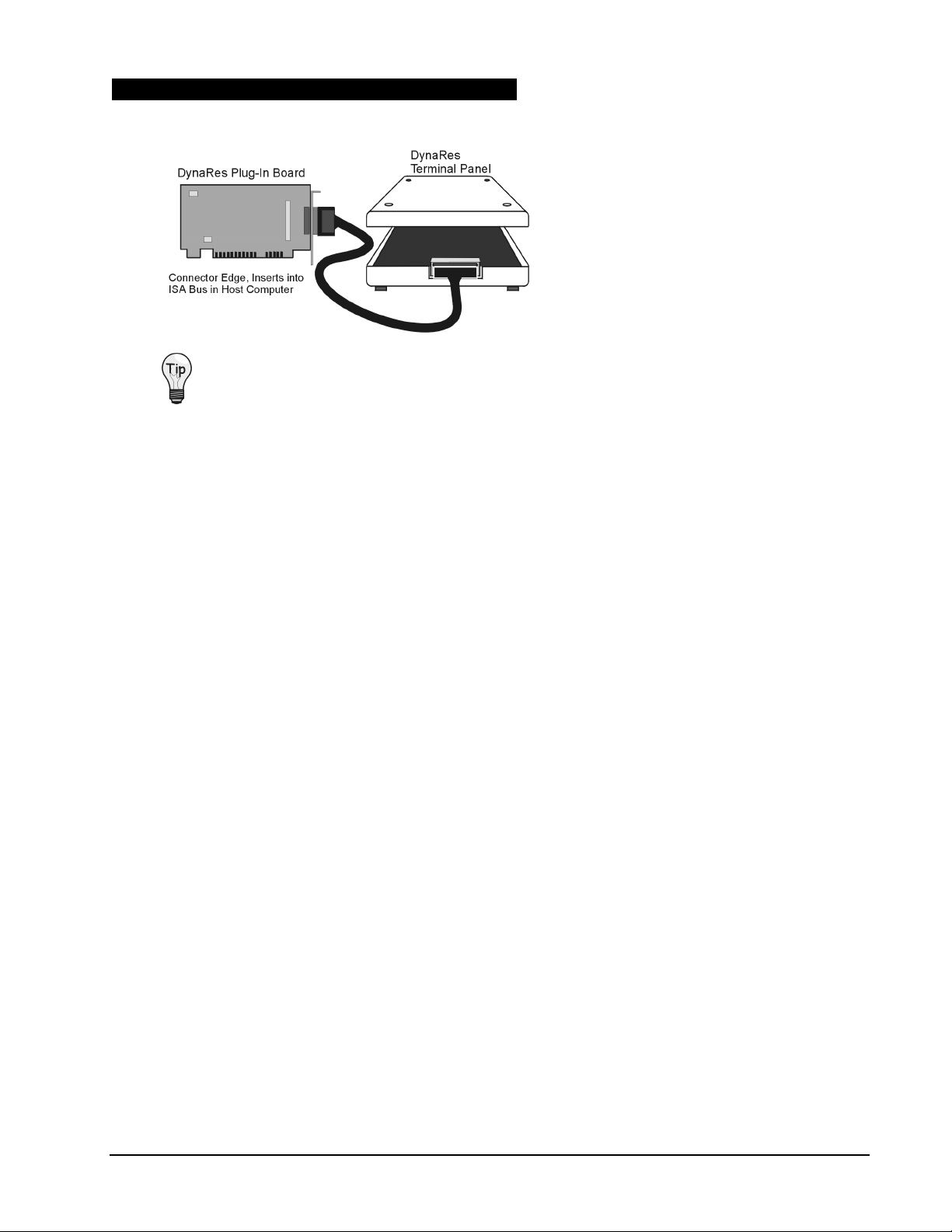
DynaRes Plug-in Boards and Terminal Panels
The DynaRes Plug-In Board inserts into a
computer’s ISA bus.
The DynaRes Terminal Panel connects to the
Plug-In Board via a supplied cable.
Be sure to consult your computer documentation, as needed.
1. Turn off your PC.
2. Remove the PC’s casing.
3. Remove the cover for the ISA slot you intend to use.
4. Insert the DynaRes Plug-In Board connector edge into an ISA slot on the host computer. If installing more
than one DynaRes board, the board numbers (for all boards except the first) will have to be changed.
5. Connect the DynaRes Terminal Panel to the DynaRes Plug-in board.
•
Some DynaRes Terminal Panels have a single 50-pin connector which mates directly with
a connector on the plug-in board.
•
Some single-slot solution DynaRes boards may require the use of a short 50-pin cable (supplied).
•
DynaRes Analog Output (ACAO) Terminal Panels connect to ACAO Plug-In Boards via a ribbon
cable (supplied).
6. Remove the DynaRes Terminal Panel’s cover.
7. Connect your application sensors to the DynaRes Terminal Panel’s screw terminals.
8. Replace the DynaRes Terminal Panel cover.
9. Replace the PC’s casing.
10. Turn on the PC.
11. Install and run the application software (DASYLab or Quick Log) as instructed on page 3 of this document.
1052-0940, rev. 1.0
DynaRes, Data Shuttle, & DataShuttle Express - Quick Start
June 1999
2
Page 3

Software Installation
DASYLab can be selected for 16-bit or 32-bit applications.
Quick Log can be used in 16-bit applications only.
Install Quick Log or DASYLab, but do not install both programs.
Installing Quick Log
There are two 3.5” disks for Quick Log, each disk having a "Setup.exe" program. Disk I is used to install
Quick Log. Disk 2 is used to optionally install an upgrade of the Windows driver to a user-defined location.
1. Insert the first 3.5" floppy disk (or CD-ROM disk, if applicable).
2. If using a 3.5” install disk, from Windows Run “A:\Setup.exe” or “ B: \Setup.exe”.
3. Follow the screen prompts (see Tip). When prompted, choose Quick Log’s installation path.
During a screen prompt, if you are not sure of what choice to make, accept the program’s default.
After the installation is complete, you must restart Windows before running Quick Log. You can run
Quick Log from the Start menu, or from the Quick Log program group.
Installing DASYLab
DASYLab is provided on a CD-ROM, and the following steps refer to installing DASYLab from a CD.
If you have no CD-ROM drive, you can use 3.5” install disks made from the CD.
1. Insert the DASYLab CD into CD-ROM drive. The CD should be recognized, automatically.
If it is not recognized, select the CD-ROM location and double click.
2. Choose the menu option, “Installation.”
3. Choose the menu option “Full” for complete program, or “Demo” for a demonstration program.
4. Select the desired install types from the options provided.
• 32-bit option is for Win NT 4.0 or Win95/98
•
16-bit option is for Win 3.1 or Win95/98
For Win 95/98, choose the 16-bit setup if there is no preference.
5. Enter your name and company information.
6. Enter the Serial Number and Key.
Keep the serial Number and Key in a safe, accessible place. You will need
these for future upgrades, or if calling technical support.
Note: You will be given the option to choose DASYLab’s installation path.
7. Choose type of IEEE Support desired. If IEEE Support is not required for your application,
use the default selection.
8. Unless you have an ACAO card, select “No” when asked to input the calibration data.
After installation is completed you will be prompted to restart Windows.
You can run the DASYLab program from the Start menu, or from the DASYLab program group.
1052-0940, rev. 1.0
• Read the Readme.wri file for the latest information regarding DASYLab.
• For a quick and easy tutorial, go to “Index” (under the Help menu) and
select “Creating your first worksheet.”
DynaRes, Data Shuttle, & DataShuttle Express - Quick Start
June 1999
3
Page 4

1052-0940, rev. 1.0
DynaRes, Data Shuttle, & DataShuttle Express - Quick Start
June 1999
4
 Loading...