

Page 1

DaqView
and
DaqViewXL
for DaqTemp Applications
967896
Page 2

1108-0902 and 457-0909
Page 3
DaqView
DaqTemp Applications
Overview……2
Starting DaqView……2
A Tour of DaqView……2
Main Window Toolbar …… 3
Channel Setup Buttons …… 3
Channel Setup Window ….. 4
A DaqView Walk-Through …… 5
Acquisition Setup……7
Data Destination……9
Pull-Down Menus……10
Charts and Meters…… 12
Analog Output Window…… 14
Digital I/O Window …… 15
Counter/Timer Window …… 15
Waveform & Digital Pattern Output Window ….. 16
Acquire ….. 18
DaqTemp Applications
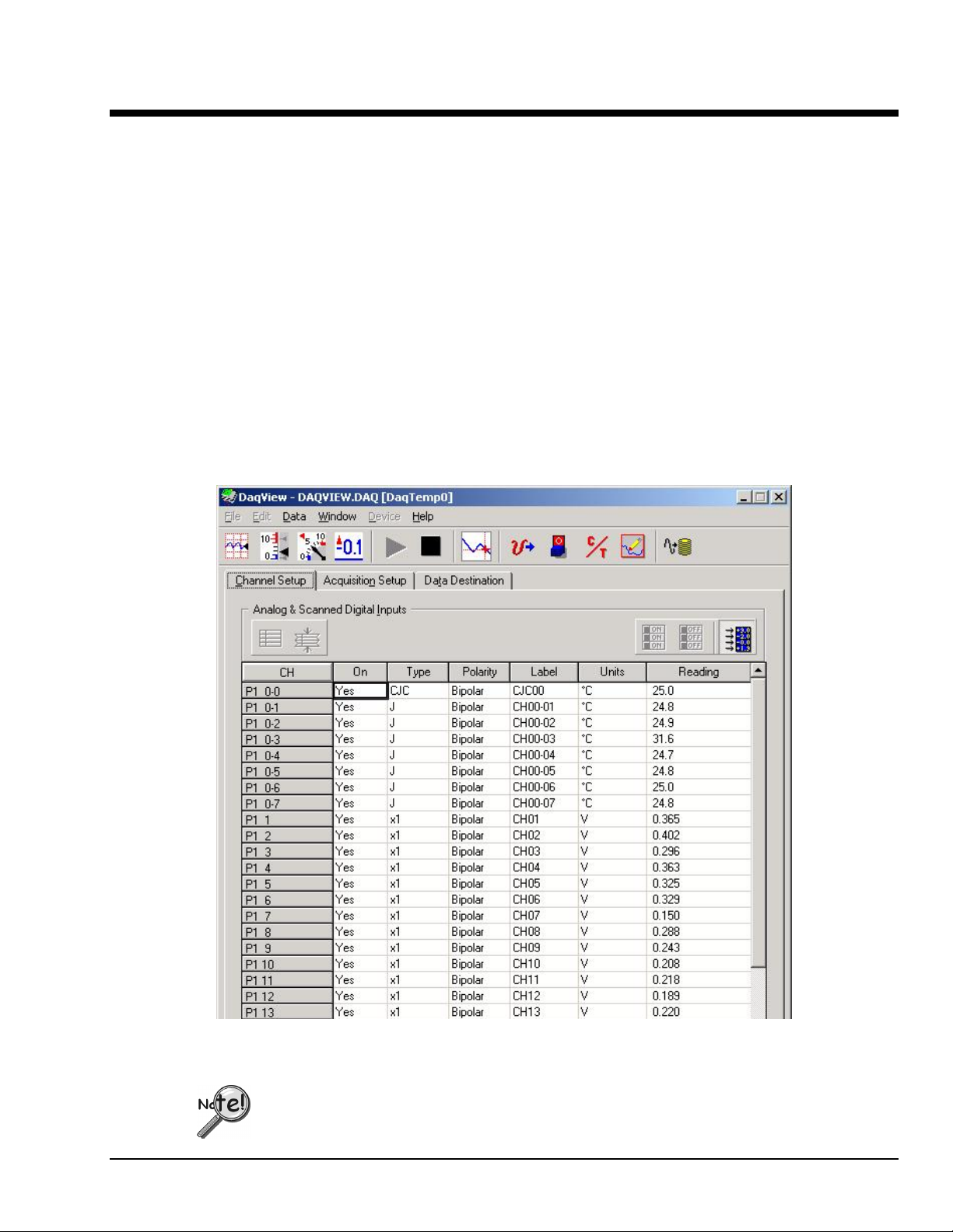
DaqView Main Window, Channel Setup Tab Selected
DaqView can only be used with one device at a time. If you desire to use DaqView for
multiple devices, you will need to run concurrent applications of the program, i.e., one for
each device you want to monitor.
967996
1108-0902, rev 2.0
DaqView, pg. 1
Page 4

Overview
DaqView is a 32-bit Windows-based data acquisition program that was designed for ease-of-use;
programming expertise is not required. DaqView allows you to:
• Set up system parameters.
• Save data to disk and transmit data to spreadsheets and databases.
• Automatically re-arm the trigger function and save data in new files as needed.
• Launch eZ-PostView, an independent post-acquisition data analysis program.
DaqViewXL is a Microsoft Excel-based “add-in.” The application is discussed in an independent document
module that is included as part of this manual.
Starting DaqView
Minimum computer requirements include:
• Intel
• 32 Mbytes of RAM
• Windows 98, Me, NT, 2000, or XP
• Data acquisition hardware
To run DaqView, double-click the DaqView icon or use your Windows desktop Start button to navigate to
the program file.
Note: If acquisition hardware is not available, or you just want to explore the software, you can select
Simulated Instrument; the main window will open (see following figure). When DaqView detects
hardware, or a simulated instrument has been selected, DaqView’s main window will open.
Note: In event of a Daq device communication problem, exit DaqView and perform a hardware test from
the Daq Configuration applet control panel.
TM
Pentium® P100, or equivalent
A Tour of DaqView
This section includes a look at DaqView’s main window, toolbar buttons, and the spreadsheet style Channel
Setup tab, which includes a Readings column.
Daq devices differ from one another in regard to functionality. Functions that are not
supported by a particular board [or device] will be grayed-out.
A Partial View of the Main Window
DaqView, pg. 2
967996
DaqTemp Applications
Page 5
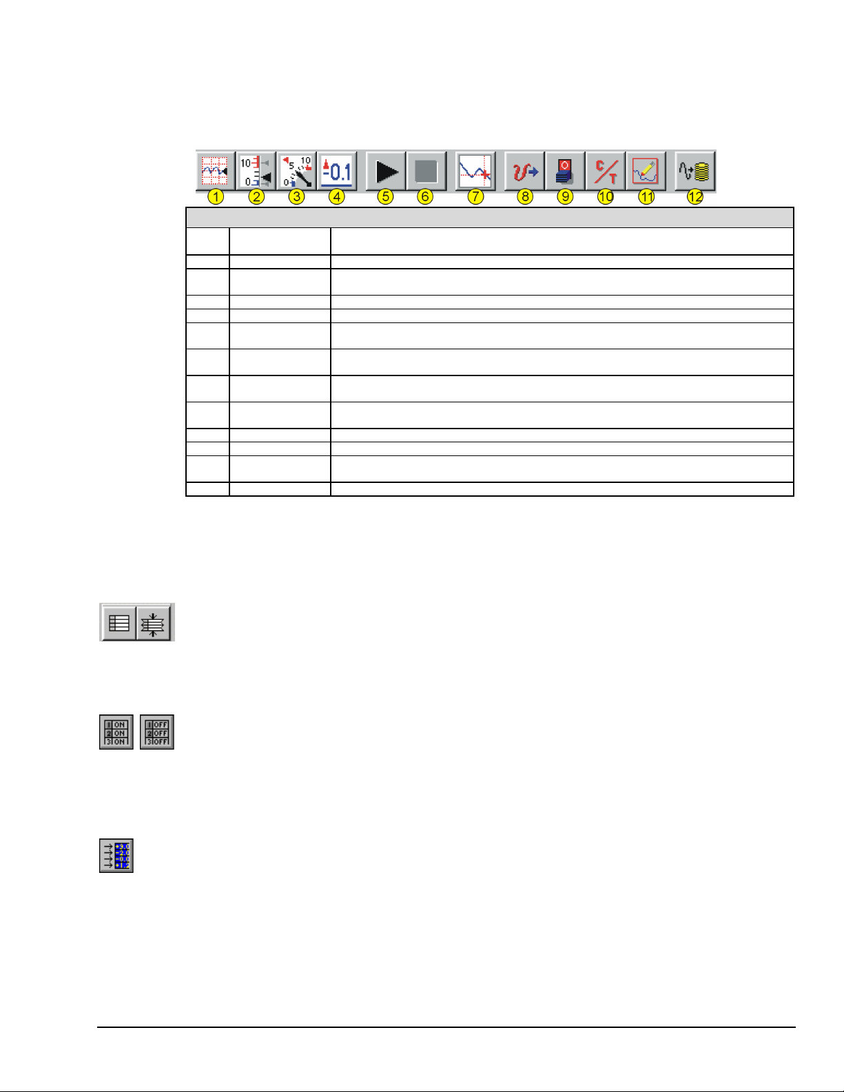
Main Window Toolbar
Each item in the main window toolbar has its own icon and is accessible from the pull-down menu. Placing
the cursor on the icon and clicking the mouse button enables the tool or opens the corresponding window.
When a function does not apply, the toolbar button will be grayed-out.
Item # Item Description
1 Charts Displays the DaqView Channel Display window.
2 Bar Graph
Meters
3 Analog Meters Displays an analog dial meter.
4 Digital Meters Displays a digital meter.
5 Start All
Indicators
6 Stop All
Indicators
7 View File Data Launches eZ-PostView, an independent post-data acquisition program.
8 Analog Output Displays the Analog Output window of the DAC channels, as applicable. DaqTemp7 and
9 Digital I/O Displays the Digital I/O window.
10 Counter/Timer Displays the Counter/Timer window.
11 Waveform &
Pattern Output
12 Acquire Activates an acquisition of data to a file.
Main Window Toolbar Items
Displays a bar graph meter.
Starts displaying data in the Reading column and any open Chart or Meters window.
Stops displaying data in the Reading column and any open Chart or Meters window.
The eZ-PostView application is covered by separate documentation.
DaqTemp14 have no DACs. DaqTemp7A has two DACs. DaqTemp14A has four DACs.
Displays the Arbitrary W aveform and Streamed Output windows.
Channel Setup Buttons
These five buttons are not a part of the main window toolbar. Instead, they reside just above the
spreadsheet on the Channel Setup tab. The reason is that they only affect the channel spreadsheet.
Show All Channels, Hide Inactive Channels
These toolbar buttons collapse or expand the Analog & Scanned Digital Inputs spreadsheet to show all
channels, whether active or not, or to hide those that are inactive. These commands are also available from
the Edit pull-down menu.
Turn All Visible Channels On, Turn All Visible Channels Off
These toolbar buttons can turn all the channels ON or OFF at a single stroke. This feature is convenient
during setup and troubleshooting or if only 1 or 2 channels must be set differently from the rest. Both these
commands are also available from the Edit pull-down menu as Make All Channels Active and Make All
Channels Inactive.
Channel Readings
This toolbar item enables/disables the Reading column of the Analog and Scanned Digital Input spreadsheet
to provide a numeric view of incoming data. This function toggles on and off when the button is repeatedly
selected. Some windows require the Reading column to be disabled while changing channels or other
parameters. This command is available from the Data pull-down menu as Enable Input Reading Column.
DaqTemp Applications
967996
1108-0902, rev 2.0
DaqView, pg. 3
Page 6
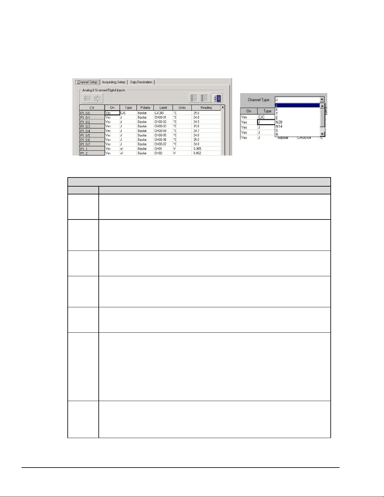
Channel Setup Window
Selecting the Channel Setup Tab displays the analog and scanned digital input channels and allows you to
configure them. Each row shows a single channel and its configuration. The number of rows may vary, but
each row has seven columns. Some columns allow blocks of cells to be altered at the same time (clicking a
column header can select the entire column). Other columns allow only a single cell to change. The table
summarizes the function of each column.
Column Description
CH
The channel number (cannot be changed from this window). This number includes the main channel
number and the expansion board number and channel (if used). Expansion channels are configured
using the Hardware Configuration window described later in this module.
Channel Setup Tab Selected
Channel Setup Window
Setting Thermocouple Types
for DaqTemp Channels
On
Type
Polarity
Label
Units
Reading
This column allows you to select whether data will be collected from that channel. When a cell or
block of cells in this column is selected, a selection box will appear that allows “Yes” to enable or
“No” to disable the channel. Double-clicking a cell in this column will toggle the channel status. The
Edit menu allows you to Make All Channels Active or Make All Channels Inactive.
This column allows you to set the gain or input type [such as thermocouple type] for each channel.
A block of cells in this column can be selected for multiple channels of the same type. Doubleclicking a cell will select the next available gain or type.
This column shows the channel polarity (unipolar or bipolar) for each channel. The polarity can be
programmed here on a per channel basis. For selected cells that can be changed, a selection box
will display “Unipolar” or “Bipolar”. Double-clicking in a cell will toggle the polarity. If hardware
cannot accept the polarity change, no selection box will be displayed.
This column contains a descriptive name for the input channel. The default label is the channel
number, but it can be changed to any 8 characters and must be unique. This label is used when
selecting a channel in the analog trigger and chart selection lists.
This column allows you to change the engineering units of each channel and apply a linear equation
to the acquired data. When a cell [or block of cells] is selected, the analog input box displays entry
options in a pull-down box. Selecting "mx+b" allows you to define the scale “m”, the offset “b”, and
the engineering units label. The "mx+b" equation is applied to the reading before it is displayed or
written to disk. The "x" in the equation is the raw DaqTemp value for the selected channel.
By default, temperature readings are in degrees Celsius (°C). However, DaqView includes "built-in"
linear factors that provide automatic conversion to degrees Fahrenheit, Rankine, or Kelvin with no
need for the user to enter “m” or “b” values. If desired, m and b values can be used to convert the
Celsius reading to a different engineering unit, for example, to a customized non-standard unit.
This column displays the device’s analog or scanned digital input readings. This column cannot be
altered by the user and is enabled by selecting Enable Input Reading Column under the Data menu
or by selecting “Start/Stop All Indicators” under the window menu. This column will update the
readings as fast as the computer will allow. The spreadsheet cannot be altered while the input
reading column is enabled.
DaqView, pg. 4
967996
DaqTemp Applications
Page 7
A DaqView Walk-Through
The following walk-through is intended to familiarize you quickly with aspects of DaqView not yet
discussed.
(1) Open DaqView. If your DaqTemp is not connected you can select Simulated Instrument as your
device.
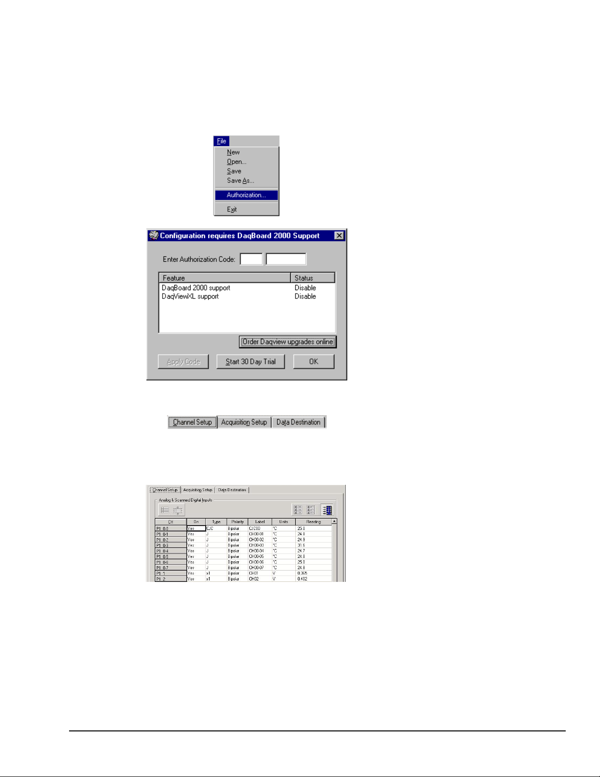
(2) From DaqView’s File menu, select
Authorization.
(3) If you ordered a DaqView upgrade, for
example, DaqViewXL, enter the Authorization
Code [found on a separate sheet] and click the
<Apply Code> button.
If you have no Authorization Code you can click
the <Start 30-Day Trial> button to enable a
temporary version of an upgrade.
Note that you can order upgrades “online.”
(4) To familiarize yourself with the three windows
available from DaqView’s main window, click the
tabs Channel Setup, Acquisition Setup,
and Data Destination.
Channel Setup displays a spreadsheet for viewing
and changing the configuration of analog and
scanned digital input channels. Each row is
dedicated to a single channel.
The columns and buttons pertaining to Channel
Setup were discussed in the preceding sections.
DaqTemp Applications
967996
1108-0902, rev 2.0
DaqView, pg. 5
Page 8
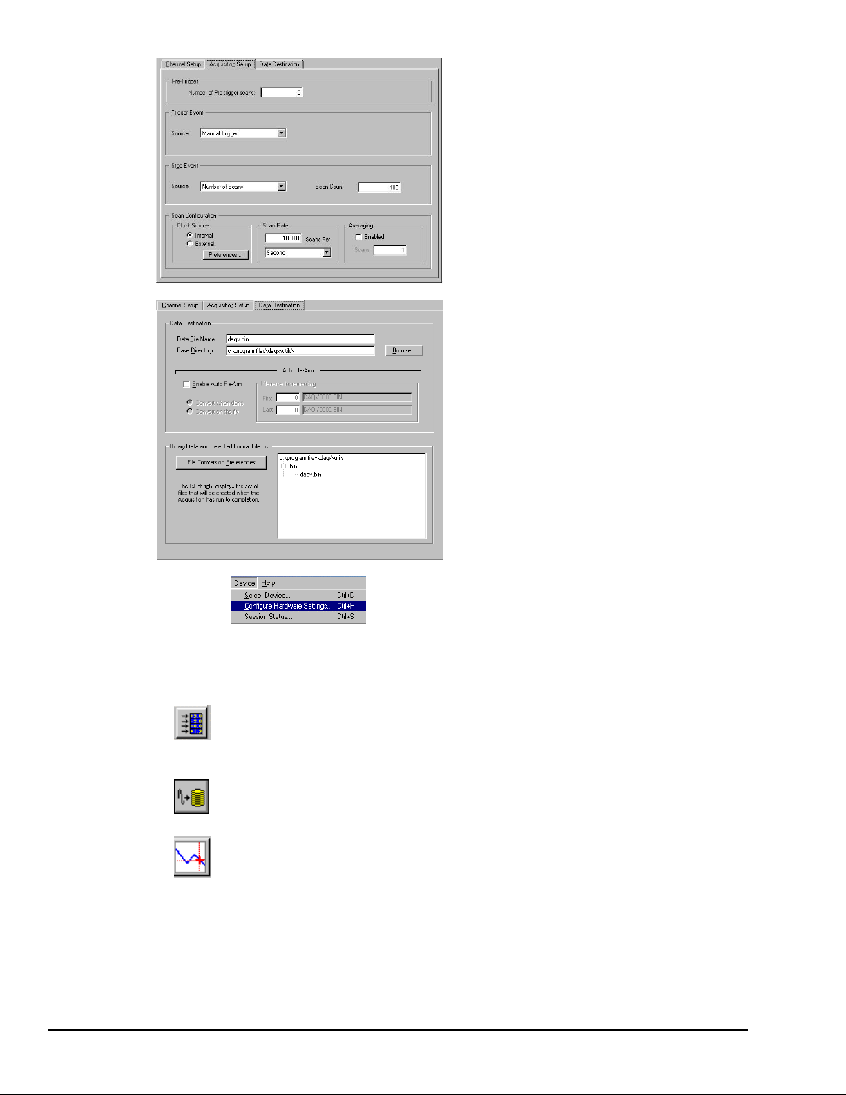
Acquisition Setup displays a window that includes
parameters for triggering and configuring the scan.
These settings are used when an acquisition to disk
is started with the toolbar’s Acquire button. When
the trigger is satisfied, scans are collected at the
selected scan frequency and stored to disk in the
designated file. Note that these parameters cannot
be altered while an acquisition is in progress.
Data Destination provides a means of designating
the desired file formats and directories for acquired
data.
From DaqView’s Device menu, select
Configure Hardware Settings.
The window Configure System Hardware will appear. The right side of the screen is used to set up
digital connections.
Click OK to return to DaqView’s main window. If Channel Setup is not selected, select it at this time.
Select the Channel Readings button. If in the Simulated Instrument mode, the Reading
column of the Analog & Scanned Digital Inputs spreadsheet will display simulated data.
Selecting the Channel Readings button again will freeze the Reading column’s display.
If working hardware is connected, the readings will quantify actual signals.
To acquire data to a file, press the Acquire button. For simulated hardware, you will be
prompted to enable a manual trigger. Binary data is acquired to a file (with default name
of daqv.bin).
This button is used to launch eZ-PostView, an independent post-data acquisition
program. eZ-PostView is discussed in a separate document and is included [in PDF
format] on the install CD.
DaqView, pg. 6
967996
DaqTemp Applications
Page 9

Acquisition Setup
Selecting the second tab of the main window displays the Acquisition Setup window. The four main parts of
this window include setup parameters for triggering and configuring the scan. These settings will be used
when an acquisition-to-disk is started by selecting “Acquire” (last item on the toolbar). When the trigger is
satisfied, the scans are collected at the selected scan frequency and stored to disk in the designated file.
Acquisition Tab Selected
Acquisition Setup Window
Parameter Description
Pre-Trigger
Trigger Event
The number of scans to acquire before the trigger event.
Selects the trigger source, depending on the device. Possible trigger sources include:
Immediately – arms and executes the trigger immediately.
Key Hit – arms the acquisition and waits for the user to press a key.
External TTL Rising/Falling – waits for a rising or falling edge slope on P1-25.
Hardware Rising/Falling Edge – monitors value with hysteresis on selected channel; triggers
when parameter is satisfied.
External TTL High/Low – waits for a TTL high or low level on pin 25 of connector P1.
Hardware Above/Below Level – monitors value on selected channel; triggers when parameter is
satisfied.
Above/Below Level – monitors value on selected channel; triggers when parameter is satisfied.
Rising/Falling Edge – monitors value with hysteresis on selected channel; triggers when
parameter is satisfied.
Inside/Outside Window – monitors upper and lower values on selected channel; triggers when
parameters are satisfied.
Digital Pattern – monitors 8-bit pattern on selected digital input channel; triggers when
parameters (less/greater than or equal to/not equal to) are satisfied.
DaqTemp Applications
967996
1108-0902, rev 2.0
DaqView, pg. 7
Page 10

Stop Event
Scan Configuration
Selects the event that stops the scanning, depending on the device connected. Possible
sources include:
Number of Scans - can range from 1 to 100,000,000. A scan includes all of the channels that
are marked as “On” in the Analog & Scanned Digital Inputs spreadsheet.
Key Hit – stops acquisition when the user presses a key.
Above/Below Level – monitors value on selected channel; stops scan when parameter is
satisfied.
Rising/Falling Edge – monitors value with hysteresis on the selected channel; stops the scan
when the parameter is satisfied.
Inside/Outside Window – monitors upper and lower values on selected channel; stops scan
when parameters are satisfied.
Digital Pattern – monitors 8-bit pattern on selected digital input channel; stops scan when
parameters (less/greater than or equal to/not equal to) are satisfied.
Clock Source
The Drop-down list provides the following options for DaqTemp:
– selects the device’s internal clock.
Internal
External
The <Preferences> button brings up a Preferences box the following options for DaqTemp:
Internal Clock Speed
Pacer Clock
File Conversion
Calibration Table
Calibration File
Zero Offset Adjustment
Channel Display
– selects an external, user-supplied clock.
- the default setting is 200 kHz.
– Enable or disable a pacer clock.
– Enable or disable a “delete Raw Binary files” notice.
– Select Factory or User calibration table.
– Included on a separate disk, the calibration file fine tunes the
accuracy of the device. Read the readme.txt file on the disk for more information.
– Protects against drift.
–Enables the expansion option type in the channel list.
DaqView, pg. 8
Preferences Box
Scan Rate
Averaging
Note: These parameters cannot be altered during an acquisition.
The scan frequency can be set in units of seconds, milliseconds, minutes, or hours via a pulldown box. Typing into the numeric field changes the rate. The maximum scan frequency is
dependent on the number of channels that are enabled and whether or not averaging is
enabled. Enabling more channels or averaging will lower the maximum scan frequency.
The checkbox allows averaging of the analog input data to be enabled or disabled. Averaging
can be used to increase the effective accuracy of a noisy signal. Averaging will increase the
actual scan frequency and number of scans, but the perceived scan frequency and number of
scans (which is set by DaqView) does not change.
967996
DaqTemp Applications
Page 11

Data Destination
Selecting the third tab of the main window displays the Data Destination window. The two parts of this
window let you designate the directory for acquired data and the desired file formats.
Data Destination Tab Selected
Data Destination Window
Parameter Description
Data Destination
Data File Name Acquired data is saved to this file name. This file always has a “.bin” file extension.
Base Directory This is the directory from which other directories are created to store the converted and
Auto Re-Arm
Binary Data and Selected Format File List
File Conversion
Preferences
The graphic display shows the directories and files created during acquisition. Double-clicking
* Note: PostView binary is not related to eZ-PostView. The later uses a format that automatically converts.
No file conversion preferences require selection in regard to eZ-PostView.
acquired data. You can type in changes or use the Browse button to direct files elsewhere,
including other disk drives.
With the Enable Auto Re-Arm box checked, you can specify when file conversions are
performed and the sequence range of incrementing file names.
This button lets you select the format of saved data. Selections include: DIAdem, ASCII text,
DADiSP, DASYLab, MATLAB, PostView Binary*, Snap-Master Binary, .wav, Universal File
Formats UFF 58A (ASCII), UFF 58B (Binary), and ME Scope. The tree shows where the
various formatted files will be saved on disk.
a directory brings up Windows Explorer. Double-clicking a file brings up any program
associated with the file type.
DaqTemp Applications
967996
1108-0902, rev 2.0
DaqView, pg. 9
Page 12

Pull-Down Menus
Some (but not all) items in the pull-down menu can also be enabled from the toolbar. Their description in
the toolbar section is more detailed than presented in this section.
File
New Set all parameters to their startup, default setting.
Open Set all parameters as directed by a specified setup file.
Save Save the existing configuration for later recall (overwrites the existing version).
Save As Saves the existing configuration for later recall; asks whether to overwrite the original
Authorization Displays the Authorization window for entering the Authorization Code.
Exit
Edit
Hide Inactive
Channels
Show All Channels This command shows all channels, whether turned on or off.
Make All Channels
Inactive
Make All Channels
Active
Fill Down
F8
File Menu Items and Descriptions
version or save under a new filename.
Leave the DaqView program.
Edit Menu Items and Descriptions
This command collapses the spreadsheet to show only those channels that are turned on.
It can be selected repeatedly as needed.
This command places a “No” in the On field of all channels. To scan only a few channels it
may be easier to make all channels inactive, then turn on the desired channels.
This command places a “Yes” in the On field of all of the channels.
For multiple cells selected within a column, this command copies the value in the top cell to
all the cells below.
Data
Data Menu Items and Descriptions
Acquire This command arms the hardware for an acquisition to disk. When the trigger is satisfied,
Convert Existing
Files
Enable Input
Reading Column
the acquisition begins. All of the interactive I/O controls are disabled while the system is
armed. No acquisition parameters can be altered at this time.
During an acquisition, a raw binary file is created and updated as data is read. This
command lets you convert raw binary files to the selected formats. This allows you to
convert files that may not have been converted when the data was acquired.
This command reads the analog inputs and scanned digital inputs and puts the numeric
values in the spreadsheet in the “Reading” column. If the Reading column is already
enabled, this command disables it.
DaqView, pg. 10
967996
DaqTemp Applications
Page 13

Window
Window Menu Items and Descriptions
Charts Displays the charts window.
Bar Graph Meters Displays a bar graph meter.
Analog Meters Displays an analog dial meter.
Digital Meters Displays a digital meter.
Start All Indicators Starts displaying data in the Reading column and any open Chart or meters window.
Stop All Indicators Stops displaying data in the Reading column and any open Chart or meters window.
View File Data Launches eZ-PostView, a post acquisition data analysis application.
Analog Output Displays the analog output window.
Digital I/O N/A
Counter/Timer N/A
Waveform &
Pattern Output
Preferences Displays a preferences dialog box that shows user-selectable options regarding the
Displays the arbitrary waveform and streamed output window.
particular Device model. For example, with a DaqTemp7A, the following
preferences can be set.
Device
Help
The internal clock speed can be set to 200 kHz or 100 kHz. The default is 200 kHz.
The Pacer Clock checkbox lets you enable a clock output.
Device Menu Items and Descriptions
Select Device
Provides a means to select an actual connected device, or a simulated instrument.
The Help menu provides access to the on-line Help file.
About provides the current software version number.
DaqTemp Applications
967996
1108-0902, rev 2.0
DaqView, pg. 11
Page 14

Charts and Meters
When you select one of the first four buttons from the main widow you access one of the following types of
display window:
Charts
Bar Graph Meters
Each of these display options is detailed shortly. Additional tool icons in charts and meters include the
following. Note that other buttons, for DaqViewXL and the post-acquisition data analysis program, are
discussed later.
Control Buttons for Charts and Meters
Charts
Charts displays real-time data in a stripchart format for several channels on the
DaqView Channel Display window.
Charts are enabled by selecting the
triangular “Play” button on the top left (see
figure). Before “playing”, at least one
chart must be assigned to an active channel
through the drop-down list on the right side
of the chart. For the selected channel, you
can change the minimum and maximum
values as needed. This command can also
be enabled from the Window pull-down
menu.
Analog Meters
Digital Meters
DaqView, pg. 12
Data is read and displayed in the charts,
meters, and Readings column as fast as the
computer will allow. When an acquisition
to disk has begun using the Acquire
command, the charts, meters, and the
Reading column take a lower priority,
updating only when there is time in the
acquisition-to-disk task. Thus, the data
seen in the charts may not be the same as
on the disk. As the scan rate is increased,
the acquisition-to-disk task will take up
more processor time and the charts will be
unable to keep up.
DaqView Display Charts
967996
DaqTemp Applications
Page 15

Bar Graph Meters
Selecting the Bar Graph Meter icon brings up
the Bar Graph window to display several
channels in bar graph format. To activate the
display, select the Start button on the left side
of the toolbar (or Start All Indicators in the
pull-down menu or in the toolbar). You can
vary the number of channels displayed by
selecting the input box at the end of the
toolbar. The Grid tool (next to last item on
toolbar) is used to arrange the display for
convenient reading. The pushpin icon in the
center of the toolbar locks this window on top
of other windows until you unlock it by
selecting the pushpin again. Right-click on a
meter to bring up an option menu.
Bar Graph Window
Analog Meters
Selecting the Analog Meter icon brings up
the Analog Meters window to display several
channels in a dial/gage format. To activate
the display, select the Start button on the left
side of the toolbar (or Start All Indicators in
the pull-down menu or in the toolbar). You
can vary the number of channels displayed by
selecting the input box at the end of the
toolbar. The Grid tool (next to last item on
toolbar) is used to arrange the display for
convenient reading. The pushpin icon in the
center of the toolbar locks this window on
top of other windows until you unlock it by
selecting the pushpin again. Right-click on a
meter to bring up an option menu.
Digital Meters
Selecting the Digital Meters icon brings up
the Digital Meters window to display several
channels in numeric format. To activate the
display, select the Start button on the left side
of the toolbar (or Start All Indicators in the
pull-down menu or in the toolbar). You can
vary the number of channels displayed by
selecting the input box at the end of the
toolbar. The Grid tool (next to last item on
toolbar) is used to arrange the display for
convenient reading. The pushpin icon in the
center of the toolbar locks this window on
top of other windows until you unlock it by
selecting the pushpin again. Right-click on a
meter to bring up an option menu.
Analog Meters Window
Digital Meters Window
DaqTemp Applications
967996
1108-0902, rev 2.0
DaqView, pg. 13
Page 16

Properties of Meter Windows
The meter windows simulate the look of 3 popular meter types: the bar graph, the analog dial, and the
digital readout. Within each meter type, you can adjust their display properties to fit your needs. While in
the meter window, place the cursor in the display area and click the right mouse button; then select
Properties. A Properties window will appear and allow you to:
• Scale - set the high and low points and the format (number of decimal places)
• Limits - set the high and low points and whether to display these limits
• Misc - set option to show the Trend Indicator and/or the Peak Hold Indicators.
Analog Output Window
The analog output window provides interactive access to the analog outputs on the “A” series DaqTemps.
DaqTemp7A has two DAC channels (DAC0 and DAC1); DaqTemp14A has four DAC channels (DAC0,
DAC1, DAC2, and DAC3).
When set to the default internal reference, these outputs can be set from 0 to +10 VDC.
The output voltage can be with the slide control, or by placing the cursor in the numeric field and entering a
valid voltage value. Selecting the Execute button sends the voltage values to the outputs.
The window is not available when the arbitrary waveform window is visible.
DaqView, pg. 14
Analog Output Window
967996
DaqTemp Applications
Page 17

Digital I/O Window
This window is displayed when the Digital I/O button on the main window is selected. It provides
interactive control of all configured digital I/O ports (as configured in the Configure System Hardware
window). The base unit has the three 8-bit ports of P2 that can be configured as either inputs or outputs.
Up to twenty 8-bit ports can be accessed when expansion boards are added. When the Execute button is
pressed, all ports configured as outputs will be updated and all input ports will be read.
Counter/Timer Window
Two C/T modes are available for the DaqTemp devices.
• Totalize Input – Counts rising or
falling edges of signals from the
related pin on P3 adapter. Each
channel has its own Reset button.
Asynchronous Digital I/O Window – P2 Digital I/O
DaqTemp Applications
• Square Wave Generator Output
– Outputs a square wave on each of
2 channels with a selectable
frequency and duty cycle.
Note: Channels that are enabled in the scan cannot be used from the asynchronous counter/timer
window.
967996
1108-0902, rev 2.0
DaqView, pg. 15
Page 18

Waveform & Digital Pattern Output Window
The “A” series DaqTemp models
have a waveform mode for their
analog output channels. DaqView
allows the DACs to be configured in
interactive mode or waveform mode.
With “A” series DaqTemps, both the
Analog Waveform and Streaming
Output tabs are enabled.
• Selecting the Analog Waveform
tab accesses the standard analog
output window.
• Selecting the Streaming Output
tab accesses the arbitrary
waveform window.
Note: This window is not available
when the analog output window is
visible.
The following material identifies the
functions of various buttons and
regions of the window. Refer to the
screen shot at the right as needed.
Waveform and Digital Pattern Output Window –
Analog Waveform Tab Selected
In the Waveform Type box, you can select a standard function generator waveform (sine, square, triangle,
sawtooth) or a freehand drawing. In Freehand, move the mouse to the waveform window and draw a
waveform using the left mouse button.
The Save Waves button allows you to save the values of each displayed waveform to disk in an ASCII
format. The files created are compatible with spreadsheets and word processors, allowing you to
numerically inspect and/or alter the saved waveforms.
Sample Waveform File Format Examples
One Channel Two Channels
2043<CR> 2432<TAB>293<CR>
1019<CR> 394<TAB>345<CR>
300<CR> 2934<TAB>3456<CR>
923<CR> 743<TAB>875 <CR>
In the two-channel example (to the immediate
left), the entry preceding the <TAB> is for
the first channel and the entry after the TAB is
for the second channel.
The Load Waves button reads any ASCII file of numbers up to the number of points specified in the
Updates per Channel field.
DaqView, pg. 16
967996
DaqTemp Applications
Page 19

The Copy Waves and Paste Waves buttons use the system clipboard to post and receive waveform data
from all DAC channels. The data formats are identical to the Save and Load operations. Copy and Paste are
recommended for use with spreadsheets to numerically inspect and/or modify waveforms. Waveforms can
also be copied and pasted from the popup menu that is displayed when the mouse is right clicked over the
Waveform display. The waveform selected in the DAC selection listbox is the target of the Cut or Paste.
If multiple channels of data are on the clipboard, you can select the one that you want to paste into the
selected DAC channel.
The size of the memory buffer allocated for each DAC channel is determined by the number of updates that
you specify. Different Daq devices have different limits on the maximum updates that can be specified.
You can select one of three clock sources to pace the DAC output. The three options are as follows:
• DAC Pacer with a rate set in the Sample Update Rate field. When using the DAC pacer, the
Update Rate field controls the speed at which the DAC is updated.
• Acq Pacer, the clock used by the analog input section of the DaqBoard. Using the Acq pacer
clock synchronizes the update of the DAC output with the analog input data collection.
• External TTL. Update rate is controlled by the rate of the clock signal applied to the external
input pin.
Note: If the DAC Pacer clock is selected, you must enter the update rate that paces the DAC outputs.
The selection for the DAC channel for which you want to create a waveform, is made in the DAC selection
listbox,. From the same listbox you can control the channel's output by clicking the checkbox on or off.
Note that DaqTemp7A, having two DACs allows for two channels to be selected. DaqTemp14A allows for
up to 4 DAC analog output channels to be selected. The non-“A” series (DaqTemp7 and DaqTemp14)
have no DACs.
In the Waveform selection box, you can select a standard function generator waveform (sine, square,
triangle, sawtooth) or an arbitrary freehand drawing. In arbitrary mode, move the mouse to the waveform
window and draw a waveform using the left mouse button. The drawn waveform will be loaded into the
channel selected in the DAC channel listbox. You can also create a waveform by right clicking the mouse
with the cursor over the waveform window. Select the waveform type from the resulting popup menu.
Repeat this process for each channel in the DAC selection listbox.
To start the waveforms playing on the DACs, click the Start Waveforms button.
Auto Scale Waveform
DaqView provides an easy method to determine the upper and lower extents of the selected DAC
waveform. Simply right click the mouse over the Waveform display, and select the Auto Scale item from
the popup menu. DaqView scans the waveform for the highest and lowest values, then sets the upper and
lower waveform range fields to these values. This causes the waveform to be displayed full scale within
the waveform display.
This is useful if the waveform is off scale on the high or low end (indicated by the range input field color set
to red) and you want to bring it back to a full scale view.
Auto Fit Waveform
The DaqView Auto Fit feature is similar to Auto Scale. However, Auto Fit causes the data to be re-scaled
so it fits full scale in the range defined by the values in the upper and lower range input fields.
Note: For some Daq hardware, when hardware triggering has been selected to trigger an acquisition, DAC1
is used internally to supply the desired threshold voltage. In this case, CH 1 is not available for
waveform output. The Copy Waves and Paste Waves buttons use the system clipboard to post and
receive waveform data. The data formats are identical to the Save and Load operations. Copy and
Paste are recommended for use with spreadsheets to numerically inspect and/or modify waveforms.
To start the waveforms playing on the DACs, click the Start Waveforms button.
Note: When the analog input section is set for analog input triggering, DAC1 is used internally to supply the
DaqTemp Applications
desired threshold voltage. In this case, DAC1 is not available for waveform output.
967996
1108-0902, rev 2.0
DaqView, pg. 17
Page 20

For DaqTemp7A and DaqTemp14A only:
Selecting the Streaming Output tab brings
up the window to configure continuous
streamed output via one or more DACs, or
digital outputs via the P3 16-bit port.
• Analog or digital output is chosen
from the Data Selection section of the
Streamed Output window.
• The Data Source section selects the
file name and type (ASCII or binary).
• Within the Output Control section, you
can select to send all samples or a
portion, and whether to continuously
repeat or stop after a specified count.
• The clock source can be an internal or
external DAC clock, or an internal or
external pacer clock.
• The Start button initiates a streamed
output.
Waveform & Digital Pattern Output
Streaming Output Tab Selected
Acquire
The Acquire selection activates an acquisition of data to file. The Event option under the Trigger Setup
portion of the Main window determines when the Acquire process is initiated. The Event selections are
detailed in the Acquisition Setup section of this chapter. After Acquire is selected, the process is automatic
beginning with the DaqView Armed screen. This screen posts the Trigger Armed time as well as the
Trigger Event information. The Acquire process makes use of the Data File Setup parameters to format
data collection.
Once the Trigger Event occurs, the DaqView Triggered screen appears. This screen allows you to witness
the data sampling parameters you set in the Main window prior to initiating the Acquire process as well as
the progress of the data acquisition.
If file conversion is selected, the Acquire process concludes by converting the generated .BIN file from
binary to ASCII data. The resulting file is saved under a user-specified directory and file name or, by
default, under the DaqView subdirectory as DAQV.TXT. This .TXT file is available for data processing or
analysis by various software packages such as DaqViewXL.
DaqView, pg. 18
967996
DaqTemp Applications
Page 21

DaqViewXL
Overview ……1
Program Requirements ……1
Installation of DaqViewXL Software ……2
Basic Function of DaqViewXL ……2
Hints and Tips for DaqViewXL ……4
Overview
DaqViewXL is a Microsoft Excel add-in that provides complete setup and data acquisition within Excel
under Windows 98, Me, NT, 2000, or XP. Acquired data is immediately placed in an active spreadsheet,
updating cells and graphics. Data is then analyzed and graphically displayed. DaqViewXL:
Once DaqViewXL is installed within Excel, the spreadsheet provides a toolbar that contains all the data
acquisition controls. This DaqViewXL tool bar (also accessible from Excel’s menu) can enable all
configuration and data acquisition tasks. The features of Excel and DaqView are seamlessly combined to
form a powerful data acquisition solution.
To run a trial version of DaqViewXL, select
“Authorization” from DaqView’s File Pull-down
Menu, then click the 30 day trial button.
Configuring an Acquisition ……3
Data Header ……3
• Augments Microsoft’s Excel spreadsheet software with data acquisition capability
• Provides strip-chart graphics for real-time data display
• Automatically converts data to engineering units
DaqViewXL performs like DaqView despite a slightly different user-interface. To set up your data
acquisition system, you just click on the Configure button in the Excel tool bar. DaqViewXL’s main
window appears with all of the controls required to configure data acquisition including setting up input and
output channels on an easy-to-use grid. Each column of the channel-configuration grid corresponds to
specific parameters in the data acquisition system and allows you to set these parameters on a per-channel
basis.
You can obtain automated reports by taking advantage of the Software Components concept. For example,
you can embed an Excel spreadsheet object into a Word document. When the spreadsheet object is
activated, it gives you access to DaqViewXL. In this case, the Word document holds all text, as well as an
embedded Excel spreadsheet object that holds raw and calculated data and graphics. Double-clicking on
the Excel object in Word can access DaqViewXL to efficiently prepare a statistical report. This compound
document allows you to collect, configure, analyze, graph, and annotate data with a few clicks of a mouse
button.
Program Requirements
DaqViewXL requires the following software:
• IOtech DaqBook/DaqBoard Series driver version 5 or later.
Installed components must include DaqView version 7.7.25 or later.
•
Microsoft Excel 97 or later
• Microsoft Windows Operating System (Windows 98, Me, NT, 2000, or XP)
Document Module, 457-0909
08-28-02
DaqViewXL, pg.1
Page 22

Installation of DaqViewXL Software
DaqViewXL is an option in DaqView that can be enabled by entering an appropriate authorization code
into DaqView’s product registration dialog. DaqViewXL can also be enabled for a 30-day trial period by
pressing the “Evaluation” button in the same dialog.
The ability to run DaqViewXL can be verified by checking the option status in DaqView’s “About” dialog.
To run DaqViewXL, simply start Excel and open the Daqviewxl.xls macro. You may be prompted about
the workbook containing macros. This is OK. The DaqViewXL file uses Excel macros to communicate with
DaqView. Click the “Enable macros” button to continue.
To enable the DaqViewXL toolbar, click View-Toolbars-DaqViewXL. You can position this toolbar just
like any other Excel toolbar.
Basic Function of DaqViewXL
DaqViewXL performs much like the standard DaqView. With Excel’s macro capabilities, you can tailor
DaqViewXL to meet various requirements. Your knowledge of Excel will help you use all its tools for
better data acquisition and processing. The following sections give you the basics of how DaqViewXL can
organize and analyze your data. These basic ideas will give you the ability to explore all DaqViewXL has
to offer. The discussion mirrors previous sections and highlights the differences between DaqViewXL and
DaqView. The Hints and Tips section gives you tools and suggestions to improve your productivity with
DaqViewXL.
DaqViewXL, pg.2
DaqViewXL Toolbar and Displays
08-28-02
Document Module, 457-0909
Page 23

Configuring an Acquisition
After installing DaqViewXL and entering Excel, click the Configure... icon (first in the DaqViewXL
toolbar) to set up your system. This launches DaqViewXL’s main screen (see following figure). This
screen is slightly different from the stand-alone version shown at the beginning of the chapter.
(Specifically, DaqViewXL does not have a PostView or DIAdem button—Excel performs those functions
better. Also, the Go button is now the 2nd button on the toolbar window rather than the main screen.) The
earlier discussion of DaqView configuration still applies.
Data Header
DaqView Screen Within Excel
DaqViewXL’s optional data header supplies the global acquisition parameters and the configuration of each
channel and places this information directly in the spreadsheet along with acquired data. This information
includes channel gain or thermocouple type, bipolar/unipolar setting, units, and channel label. To activate
Data Headers select the Use Data Headers icon in the DaqViewXL toolbar.
Document Module, 457-0909
DaqViewXL Data Header
08-28-02
DaqViewXL, pg.3
Page 24

Hints and Tips for using DaqViewXL
• Do not run DaqView first and then try to use DaqViewXL. When DaqViewXL runs, DaqView is put into a
special "server" mode which supports transactions with "client" applications such as Excel. Normally
DaqView does not run in this mode and cannot support DaqViewXL.
• When you acquire data into a worksheet, some of the data may be displayed as a string of hash marks
(e.g. ######). Excel will do this whenever the column is not wide enough to display all the digits of a
number. To eliminate the hash marks, just widen the column. An easy way to do this is to use the
"Format, Column, Auto Fit Selection" menu command. Immediately after an acquisition, all the rows and
columns of data are selected. Click this menu item to automatically fit all the columns to the new data.
•
You can start an acquisition from an Excel macro as shown in the following VBA macro code example:
Sub Macro1()
Application.Run Macro:="menuGoDoIt"
End Sub
This is equivalent to clicking the Go! button on the DaqViewXL toolbar. It arms the hardware for an
acquisition, and if DaqView is set up to trigger on "External TTL" or "Channel Value", the acquisition will
take place automatically when the trigger condition is met. For acquisitions configured to trigger on a "Key
Hit", the acquisition will not start until the user presses the "Manual Trigger" button on the "DaqView
Armed" dialog box.
To automatically press this button after arming DaqView use the following macro:
Sub ArmAndKeyHit()
Application.Run Macro:="menuGoDoIt" 'presses the Go! button
SendKeys "{ENTER}" 'presses the space bar
End Sub
This macro will start a "Key Hit" acquisition immediately.
Note: Macro1, shown above, was generated by Excel's macro recorder.
•
If you chose to customize DaqViewXL’s toolbar, you should avoid removing buttons. If DaqViewXL
detects missing buttons it will prompt you to allow it to remove the toolbar and recreate it with all buttons.
You can decline to do so, but DaqViewXL will continue to ask you to recreate the toolbar each time it
starts-up. You can add buttons, rearrange them, and re-size the toolbar without getting this prompt.
• If DaqView cannot connect to your hardware on start-up, it will automatically switch to the Simulated
Instrument mode when loaded from DaqViewXL.
DaqViewXL, pg.4
08-28-02
Document Module, 457-0909
 Loading...