

Page 1

Daq PC-Cards
(Daq/112B & Daq/216B)
User's Manual
Data Acquisition for Notebook, Desktop, and Tower PCs
the smart approach to instrumentation ™
IOtech, Inc.
25971 Cannon Road
Cleveland, OH 44146-1833
Phone: (440) 439-4091
Fax: (440) 439-4093
E-mail (sales): sales@iotech.com
E-mail (post-sales): productsupport@iotech.com
Internet: www.iotech.com
Daq PC-Cards
Data Acquisition for PCs
p/n
457-0908
(Daq/112B & Daq/216B)
Rev.
2.0
© 1998 … 2003 by IOtech, Inc.
Printed in the United States of America
928596
Page 2

Daq PC-Cards User’s Manual
Page 3
Warranty Information
Your IOtech warranty is as stated on the product warranty card. You may contact IOtech by phone,
fax machine, or e-mail in regard to warranty-related issues.
Phone: (440) 439-4091, fax: (440) 439-4093, e-mail: sales@iotech.com
Limitation of Liability
IOtech, Inc. cannot be held liable for any damages resulting from the use or misuse of this product.
Copyright, Trademark, and Licensing Notice
All IOtech documentation, software, and hardware are copyright with all rights reserved. No part of this product may be
copied, reproduced or transmitted by any mechanical, photographic, electronic, or other method without IOtech’s prior
written consent. IOtech product names are trademarked; other product names, as applicable, are trademarks of their
respective holders. All supplied IOtech software (including miscellaneous support files, drivers, and sample programs)
may only be used on one installation. You may make archival backup copies.
FCC Statement
IOtech devices emit radio frequency energy in levels compliant with Federal Communications Commission rules (Part 15)
for Class A devices. If necessary, refer to the FCC booklet How To Identify and Resolve Radio-TV Interference Problems
(stock # 004-000-00345-4) which is available from the U.S. Government Printing Office, Washington, D.C. 20402.
CE Notice
Many IOtech products carry the CE marker indicating they comply with the safety and emissions standards of the
European Community. As applicable, we ship these products with a Declaration of Conformity stating which
specifications and operating conditions apply.
Warnings, Cautions, Notes, and Tips
Refer all service to qualified personnel. This caution symbol warns of possible personal injury or equipment damage
under noted conditions. Follow all safety standards of professional practice and the recommendations in this manual.
Using this equipment in ways other than described in this manual can present serious safety hazards or cause equipment
damage.
This warning symbol is used in this manual or on the equipment to warn of possible injury or death from electrical
shock under noted conditions.
This ESD caution symbol urges proper handling of equipment or components sensitive to damage from electrostatic
discharge. Proper handling guidelines include the use of grounded anti-static mats and wrist straps, ESD-protective
bags and cartons, and related procedures.
This symbol indicates the message is important, but is not of a Warning or Caution category. These notes can be of
great benefit to the user, and should be read.
In this manual, the book symbol always precedes the words “Reference Note.” This type of note identifies the location
of additional information that may prove helpful. References may be made to other chapters or other documentation.
Tips provide advice that may save time during a procedure, or help to clarify an issue. Tips may include additional
reference.
Specifications and Calibration
Specifications are subject to change without notice. Significant changes will be addressed in an addendum or revision to
the manual. As applicable, IOtech calibrates its hardware to published specifications. Periodic hardware calibration is
not covered under the warranty and must be performed by qualified personnel as specified in this manual. Improper
calibration procedures may void the warranty.
Quality Notice
IOtech has maintained ISO 9001 certification since 1996. Prior to shipment, we thoroughly test our products and
review our documentation to assure the highest quality in all aspects. In a spirit of continuous improvement, IOtech
welcomes your suggestions.
Daq PC-Cards User’s Manual
iii
897197
Page 4
CAUTION
Using this equipment in ways other than described in this manual can cause
personal injury or equipment damage. Before setting up and using your
equipment, you should read all documentation that covers your system.
Pay special attention to Warnings and Cautions.
Note:
PDF
457-0908
PDF
457-0909
During software installation, Adobe
®
PDF versions of user manuals will automatically
install onto your hard drive as a part of product support. The default location is in the
Programs group, which can be accessed from the Windows Desktop. Initial navigation
is as follows:
Start [on Desktop] ⇒ Programs ⇒ IOtech DaqX Software
You can also access the PDF documents directly from the data acquisition CD by using
the <View PDFs> button located on the opening screen.
Refer to the PDF documentation for details regarding both hardware and software.
®
A copy of the Adobe Acrobat Reader
is included on your CD. The Reader provides
a means of reading and printing the PDF documents. Note that hardcopy versions of
the manuals can be ordered from the factory.
Daq PC_Card Users Manual.pdf
Provides instructions for installing a Daq/112B and Daq/216B PC-Card.
The following PDFs are companion documents.
DaqView_DaqViewXL.pdf
Discusses how to install and use these “out-of-the-box” data acquisition programs.
iv
PostAcquisition Analysis.pdf
Discusses eZ-PostView, a free post-data acquisition analysis program and two others,
PDF
1086-0926
1086-0922
eZ-FrequencyView and eZ-TimeView. These last two applications have more features
and are available for purchase. They can; however, be used freely during a 30-day
trial period.
DBK Options.pdf
The DBK Option Cards and Modules Manual discusses each of the DBK products
PDF
457-0905
available at the time of print.
Note: Only passive DBKs, i.e., DBK1, DBK11A, and DBK40 pertain to the
Daq PC-Card.
ProgrammersManual.pdf
The programmer’s manual pertains to developing custom programs using
PDF
1008-0901
Applications Program Interface (API) commands.
Programmers should check the readme.file on the install CD-ROM for the location of
program examples included on the CD.
897197
Daq PC-Cards User’s Manual
Page 5

Table of Contents
1 – Daq Systems, A Brief Overview
Daq Systems, the Modular Concept ……1-1
DaqBooks, DaqBoards, & Daq PC-Cards….1-2
Using DBK Cards & Modules for Signal Conditioning …1-3
Daq Software …… 1-3
2 – Installing Daq PC-Cards
Appendix A - Specifications, Daq PC-Cards
Appendix B - Removal of .inf files and Device for PCMCIA Card Applications
Your order was carefully inspected prior to shipment. When you receive your system, carefully
unpack all items from the shipping carton and check for physical signs of damage that may have
occurred during shipment. Promptly report any damage to the shipping agent and your sales
representative. Retain all shipping materials in case the unit needs returned to the factory.
Daq PC-Cards User’s Manual
v
897197
Page 6

This page is intentionally blank.
vi
897197
Daq PC-Cards User’s Manual
Page 7

Daq Systems, a Brief Overview 1
Daq Systems, the Modular Concept …… 1-1
DaqBooks, DaqBoards, and Daq PC-Cards …… 1-2
Using DBK Cards and Modules for Signal Conditioning ….. 1-3
Daq Software ……1-3
Daq Systems, the Modular Concept
Daq equipment and software form a modular, interrelated family of products that provide great flexibility
in data acquisition system design. This flexibility allows for the development of custom systems that are
unique to the user, and which can be optimized for his or her specific application needs. With the Daq
product line, system expansion or redesign can typically be accomplished with relative ease.
• Primary Acquisition Device. This is the main data acquisition device, e.g., a DaqBook, DaqBoard,
or Daq PC-Card. These devices provide a vital data conversion and communications link between
the data source of transducers and signal conditioners and the data processor of the host computer.
Note the DaqBoards can be one of three types: (1) ISA, (2) PCI, or (3) compact PCI (cPCI).
• DBK Option Cards and Modules. Over 35 DBK cards and modules (the number is constantly
growing) provide various types of signal conditioning and system expansion. Note that certain DBK
modules exist for the purpose of supplying power to other members of the acquisition system. The
DBK options are discussed in a DBK Basics document module and in the detailed DBK Option
Cards and User’s Manual (p/n 457-0905).
Note: Only passive DBKs, such as the DBK1 BNC module, the DBK11A screw terminal card, and
the DBK40 BNC analog interface, can be used with a Daq PC-Cards.
Reference Note:
DBK options are discussed in the DBK Option Cards and Modules User’s Manual
(p/n 457-0905). As a part of product support, this manual is automatically loaded onto
your hard drive during software installation. The default location is the Programs
directory, which can be accessed through the Windows Desktop.
• Software. DaqView out-of-the-box software provides a graphical user interface with easy to read
spreadsheet formats for viewing channel data, as well as a choice of analog, digital, and bar-graph
meters. Waveform analysis can be performed, when applicable. A product support option, included
on the data acquisition CD, provides a means of performing post data analysis. More information is
included in the software-specific PDF documents that are installed on your hard-drive as a part of
product support.
In addition to the included out-of-the-box software, Daq products can be controlled via user-written
custom programs through Applications Program Interface (API). Several languages are supported,
e.g., C/C++, VisualBASIC, Delphi.
Daq Systems
Reference Note:
Programming topics are covered in the Programmer’s User Manual (p/n 1008-0901).
As a part of product support, this manual is automatically loaded onto your hard drive
during software installation. The default location is the Programs group, which can
be accessed through the Windows Desktop.
Overview 1-1
978697
Page 8
DaqBooks, DaqBoards and Daq PC-Cards
Daq products connect to one or more DBKs on their signal input side and a computer on their output side.
Each type of Daq device connects to the computer in a different way:
• The DaqBook is an external module that connects to a computer’s enhanced parallel port (EPP)
interface or PC-Card link.
• The DaqBoard [ISA type] board is an internal card that plugs into an ISA-bus slot within a
computer.
• DaqBoard/2000 Series Boards plug into a PCI-bus slot, within a host PC.
• cPCI DaqBoard/2000c Series boards plug into a cPCI-bus slot, within a host PC.
• The Daq PC-Card slides into the PCMCIA slot of a host computer, typically a notebook PC.
Features common to the Daq products include:
• 100-kHz channel-to-channel scan and gain switching (10 µs);
200-kHz for DaqBoard/2000 Series and DaqBoard/2000c Series Boards.
• 512-location sequence memory that can be loaded with any combination of channels and gains.
• Ability to access up to 256 different channels of DBK signals while maintaining the channel-to-
channel scan rate. The DBK expansion options can accommodate mixed-signal inputs from
thermocouples and RTDs to isolated high-voltage inputs and strain gages.
• Ability to handle 8 differential or 16 single-ended signal inputs without DBK expansion units.
• Ability to handle fixed digital I/O up to 4 TTL lines in and 4 TTL lines out (accessible only if no
analog expansion cards are in use).
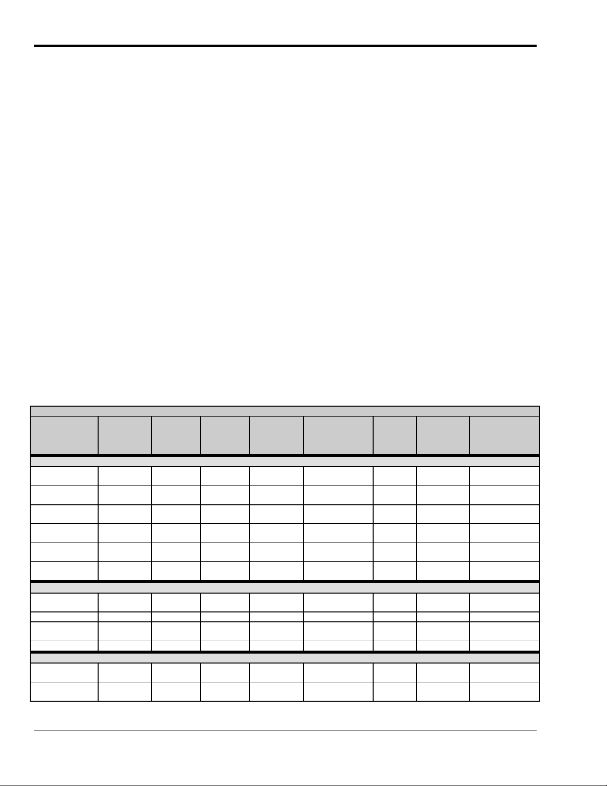
The following table lists various features of DaqBooks, ISA-DaqBoards, and Daq PC-Cards. Note that
PCI and cPCI-type DaqBoards (the DaqBoard/2000 Series and DaqBoard/2000c Series Boards) are
covered in separate documentation.
Daq Products, Models and Features
Models
DaqBooks
DaqBook/100 12 bit 2 Jumper Jumper 16 high speed
DaqBook/112 12 bit 2 Jumper Jumper N/A N/A 8.5×11
DaqBook/120 12 bit 2 Jumper Jumper 16 high speed
DaqBook/200 16 bit 2 Software Software 16 high speed
DaqBook/216 16 bit 2 Software Software N/A N/A 8.5×11
DaqBook/260 16 bit 2 Software Software 16 high speed
ISA-DaqBoards
DaqBoard/100A 12 bit 2 Sequencer Software 16 high speed
DaqBoard/112A 12 bit 2 Sequencer Software N/A N/A 4.5×13.125 970 mA @ 5V
DaqBoard/200A 16 bit 2 Sequencer Software 16 high speed
DaqBoard/216A 16 bit 2 Sequencer Software N/A N/A 4.5×13.125 1340 mA @ 5V
Daq PC-Cards
Daq/112B 12 bit N/A Bipolar
Daq/216B 16 bit N/A Bipolar
* Does not include power consumption of internal DBK options.
A/D
Resolution
Analog
Output
Channels
Unipolar/
Bipolar
Selection
Only
Only
Single-
ended/
Differential
Selection
Software N/A N/A 3.375×0.2 160 mA @ 5V
Software N/A N/A 3.375×0.2 160 mA @ 5V
Programmable
Digital I/O
Lines
24 gen purpose
24 gen purpose
24 gen purpose
24 gen purpose
24 gen purpose
24 gen purpose
Program
mable
Counter/
Timers
5 ch
7 MHz
5 ch
7 MHz
5 ch
7 MHz
5 ch
7 MHz
5 ch
7 MHz
5 ch
7 MHz
Size
(inches)
8.5×11
×1.375
×1.375
8.5×11
×1.375
8.5×11
×1.375
×1.375
11×13
×3.5
4.5×13.125 1330 mA @ 5V
4.5×13.125 1700 mA @ 5V
Power
Consumption
510 mA @ 12V
360 mA @ 12V
510 mA @ 12V
620 mA @ 12V
600 mA @ 12V
mA @ 12V
620
*
1-2 Overview
Daq Systems
978697
Page 9

Using DBK Cards and Modules for Signal Conditioning
The DBK signal-conditioning cards and module are designed for use with DaqBooks, LogBooks, and
various types of data acquisition boards, i.e., ISA, PCI, and compact PCI (cPCI) types. The DBKs perform
best when used with an acquisition device that can dynamically select channel, gain, and range. DBK
cards and modules with dynamic channel and gain/range selection allow for high channel-to-channel scan
rates with a variety of transducers.
Note: Only passive DBKs, such as the DBK1 BNC module, the DBK11A screw terminal card, and the
DBK40 BNC analog interface, can be used with Daq PC-Cards.
DBK output signals can be bipolar, e.g., -5 to +5 V, or unipolar, e.g., 0 to 10 V. The user can select a
range of relevant values to correspond to the lowest signal (e.g., -5 or 0 V) and the highest signal (e.g., 5 or
10 V) signal. This type of range selection guarantees the highest resolution in 12-bit or 16-bit conversion.
DBK modules share the same footprint as the DaqBook and a typical notebook PCs; allowing for
convenient stacking. The majority of these modules have their own power supply; however, several
options exist for packaging and powering the DBKs.
Reference Note:
DBK options are detailed in the DBK Option Cards and Modules User’s Manual
(p/n 457-0905). As a part of product support, this manual is automatically loaded onto your
hard drive during software installation. The default location is the Programs directory, which
can be accessed through the Windows Desktop.
Daq Software
The Daq devices have software options capable of handling most applications. Three types of software are
available:
Ready-to-use programs are convenient for fill-in-the-blank applications that do not require programming
for basic data acquisition and display:
• ready-to-use graphical programs, e.g., DaqView, DaqViewXL, and post acquisition data analysis
programs such as PostView, DIAdem, and eZ-View
• drivers for third-party, icon-driven software such as DASYLab and LabView
• various language drivers to aid custom programming using API
• DaqView is a Windows-based program for basic set-up and data acquisition. DaqView lets you
select desired channels, gains, transducer types (including thermocouples), and a host of other
parameters with a click of a PC’s mouse. DaqView lets you stream data to disk and display data
in numerical or graphical formats. PostView is a post-acquisition waveform-display program
within DaqView.
• DaqViewXL allows you to interface directly with Microsoft Excel to enhance data handling and
display. Within Excel you have a full-featured Daq control panel and all the data display
capabilities of Excel.
• Post acquisition data analysis programs, e.g., PostView, DIAdem, and eZ-View, typically allow
you to view and edit post-acquisition data.
• The Daq Configuration control panel allows for interface configuration, testing, and
troubleshooting.
Each Daq system comes with an Application Programming Interface (API). API-language drivers include:
C/C++, Delphi, and Visual Basic. The latest software is a 32-bit version API.
Daq Systems
Overview 1-3
978697
Page 10

Reference Notes:
Analysis User’s Guide, are not included as part of the hardcopy manual, but are
The software document modules, DaqView, DaqViewXL, and Post Acquisition Data
➣
available in PDF version. See the PDF Note, below.
➣
Programming topics are covered in the Programmer’s User Manual (1008-0901). As a
part of product support, this manual is automatically loaded onto your hard drive during
software installation. The default location is the Programs directory, which can be
accessed through the Windows Desktop.
®
PDF
Note:
During software installation, Adobe
install onto your hard drive as a part of product support. The default location is in the
PDF versions of user manuals will automatically
Programs group, which can be accessed from the Windows Desktop. Refer to the PDF
documentation for details regarding both hardware and software.
A copy of the Adobe Acrobat Reader
®
is included on your CD. The Reader provides
a means of reading and printing the PDF documents. Note that hardcopy versions of the
manuals can be ordered from the factory.
1-4 Overview
Daq Systems
978697
Page 11

Installing Daq PC-Cards 2
This chapter provides basic installation instructions for Daq PC-Cards for use with notebook PCs, or for
use with desktop or tower-type PCs that have a PCMCIA slot. The Daq PC-Cards comply with PC Card
Standard Specification 2.1, PCMCIA Type II (5mm). Input power for the Daq PC-Card comes from the
host computer. The PC-Cards do not provide output power.
A CA-134 Interface Cable provides DB37 termination to the inputs of the Daq PC-Card. The CA-134 can
connect the Daq PC-Card to a single “passive” card or module, for a variety of input signals. The passive
DBKs are:
• DBK1 – 16 Connector BNC Module
• DBK11A – Screw Terminal Option Card
• DBK40 – BNC Analog Interface
Reference Note:
Daq PC-Cards plug into a PCMCIA Type II slot. The cards will also work in
PCMCIA Type III slots. Consult your PC owner’s manual as needed.
Note: Daq PC-Cards are not compatible with Windows NT operating systems.
Step 1
(1) Install Software &
Product Support
(4) Configure &
Test
(2) Install the PC-Card
PC-Card Installation, A Pictorial Overview
- Install Software and Product Support
IMPORTANT: Software must be installed before installing hardware.
Remove
1.
Programs feature.
2. Place the Data Acquisition CD into the CD-ROM drive. Wait for PC to auto-run the CD. This may
take a few moments, depending on your PC. If the CD does not auto-run, use the Desktop’s
Start/Run/Browse feature.
3. After the intro-screen appears, follow the screen prompts.
Upon completing the software installation, continue with step 2, Install and Configure the PC-Card.
previous version Daq drivers, if present. You can do this through Microsoft’s Add/Remove
(3) Connect the Interface Cable
Daq PC-Card User’s Manual
928596
Installation 2-1
Page 12

Step 2
- Install the PC-Card
To avoid installing the wrong driver, be sure to use the instructions that are intended for
your PC’s Windows operating system. Refer to the following sections as applicable.
Regardless of which Windows operating system being used, place the Data Acquisition CD into your CD
ROM drive and …
(a)
If you have not yet installed the software and product support for your device do so at this time.
See Step 1 on page 2-1.
(b)
If you have already installed the software and product support for your PC-card, and if your CD
drive has auto-run, wait for the Master Setup Screen to appear, then click <Exit> before
continuing with the steps for the applicable OS-system.
➣
Windows XP …… pg. 2-2
Windows 2000 …… pg. 2-3
➣
➣
Windows95/98/Me …… pg. 2-4
➣
Windows NT …… Not Compatible
☛
For Windows XP Operating Systems Only
1. With your computer system powered up, insert the Daq PC-card into PCMCIA slot 0.
Windows XP will start the Hardware Wizard.
If the Windows Operating System detects the Daq PC-Card, skip directly to the section
entitled, Connect the Interface Cable [Step 3]. The procedure begins on page 2-5.
2. After the dialog box appears, verify that “Install from a list or specific location” is selected.
3. Click <Next>. A new dialog box will appear.
4. Check “Include this location in the search.”
5. Click <Browse,> then expand the CD-ROM node that is labeled “IOtech.”
6. Highlight the “Windows 2K Driver Disk” folder.
7. Select the file named, “DAQPCC2K.INF;” then click <Open>.
8. Click <Ok>. A dialog box will appear, indicating the driver path.
9. Click <Next>. Windows will locate the device driver, and then install the software.
10. After the software install is complete, click <Finish>. The Hardware Wizard will close.
This completes the driver installation for Windows XP.
2-2 Installation
928596
Daq PC-Cards User’s Manual
Page 13

☛
For Windows 2000 Operating Systems Only
1. Insert the Daq PC-Card, label-side up, into your computer’s PCMCIA adapter slot.
A dialog box should appear, indicating that Windows has begun the installation process; and
a
“Found New Hardware Wizard” will open, indicating that Windows 2000 is ready to install
drivers for the new hardware.
If the Windows Operating System detects the Daq PC-Card, skip directly to the section
entitled, Connect the Interface Cable [Step 3]. The procedure begins on page 2-5.
3. Click <Next>. The Wizard will proceed to a screen with the text, “Install Hardware Device
Drivers.”
4. Select the radio button that reads, “Search for a suitable driver for my device.”
5. Click <Next>. The “Locate Driver Files” screen appears.
6. Check the “Specify a location” check box. Then click <Next>.
At this point you will be prompted to insert the manufacturer’s installation disk. Click
<OK>.
7. Using Window’s <Browse> feature, locate your Data Acquisition CD.
8. Expand the contents of the CD; then click on the folder labeled, “Windows 2K Driver
Disk.”
9. Select the file named, “DAQPCC2K.INF;” then click <Open>. You will once again see the
Hardware Wizard’s prompt to insert the manufacturer’s installation disk.
10. Click <Ok>.
A screen with the text, “Driver Files Search Results,” appears.
The screen identifies the device and driver that were found.
11. Click <Next> to install the driver.
12. After the Hardware Wizard indicates that “Windows has finished installing the software for
this device,” Click <Finish.>
This completes the Windows 2000 Software setup for the Daq PC-Card.
Daq PC-Card User’s Manual
928596
Installation 2-3
Page 14

☛
For Windows 95/98/Me Operating Systems Only
1. Insert the Daq PC-Card, label-side up, into your computer’s PCMCIA adapter slot.
A dialog box should appear, indicating that Windows has begun the installation process for
your hardware; then the “Add New Hardware Wizard” will open, indicating that Windows is
ready to install drivers for the new hardware.
If the Windows Operating System detects the Daq PC-Card, skip directly to the section
entitled, Connect the Interface Cable [Step 3]. The procedure begins on page 2-5.
2. Click <Next>. The Wizard will proceed to a second screen that pertains to how the new
driver is to be located.
3. Windows 95/98 Users
: Select the radio button that reads, “Search for the best driver for
your device.”
Windows Me Users
: Select the radio button that reads, “Specify the location of the driver.”
4. Click <Next>. A screen for locating driver files appears.
5. Windows 95/98 Users
: Ensure that only the “Specify a location” check box is selected.
Windows Me Users
: Ensure that the radio button, “Search for the best driver for your
device” is selected; and select the two check boxes located above the browse pull-down list.
These are: “Removable Media,” and “Specify a Location.”
6. Using Window’s <Browse> feature, locate your Data Acquisition CD.
7. Expand the CD contents and click on the folder named “Windows 9x Driver Disk.”
Note that the Windows 9x Driver Disk folder is the correct folder for both Windows 9x and
Windows Me applications.
8. Click <OK.> The Hardware Wizard now displays the driver disk location in the browse
box.
9. Click <Next.>.
2-4 Installation
10. Windows Me
users - select the radio button for installing “The updated software,” and then
click <Next.> This step does not apply to Windows 95/98.
The Hardware Wizard indicates its search results, i.e., the device, the port, and the location of
the driver. Windows 95/98/Me will use the DAQPCC.INF file.
11. Verify that the DAQPCC.INF file has been located; then click <Next> to indicate that the
driver is suitable. Windows will begin the install.
Note: Windows may prompt you to insert the Windows CD so it can install Microsoft Drivers
that are not found on your PC. If prompted for the Windows CD, remove the data
acquisition CD and insert the Windows CD; then click <Ok.>
12. The Hardware Wizard will inform you when the installation is complete.
At that point click <Finish.>
This completes the Windows 95/98/Me Software setup for the Daq PC-Card.
928596
Daq PC-Cards User’s Manual
Page 15

Step 3
- Connect the Interface Cable
Digital I/O is supported and includes four general-purpose digital inputs and four general-purpose digital
outputs. The PC can access these TTL-level digital I/O lines when the Daq PC-Card is not transferring
data from the A/D converter.
Daq/112B PC-Card, before and after attaching to a CA-134 Interface Cable
Damage to the card or cable may result if not properly connected! Never force the
connection. The Daq PC-Card and cable are keyed, and should connect easily when
properly oriented. Make sure the connectors slide together at a level angle.
Excessive or angular force can damage the connectors.
To connect the Daq PC-Card to the Interface Cable (CA-134):
1. Hold the Daq PC-Card so that the label is face up and the bottom edge is facing you.
2. Verify key alignment is correct for the card and the cable.
3. Depress the cable’s spring-clips and connect the cable to the PC-Card.
4. After connection is made, release the spring-clips.
The following page pertains to connecting a passive DBK card or module to the CA-134 cable,
with use of a CN-86-F interface.
Daq PC-Card User’s Manual
928596
Installation 2-5
Page 16

Connecting the PC-Card to a Passive DBK Card or Module
A CA-134 Interface Cable provides a DB37 P1 connection for the Daq PC-Card. The CA-134 can connect
the Daq PC-Card to a single “passive” card or module. The passive DBKs are:
• DBK1 – 16 Connector BNC Module
• DBK11A – Screw Terminal Option Card
• DBK40 – BNC Analog Interface
Note: A CN-86-F (dual-socket type, DB37 connector) is used as an interface to connect CA-134’s
male P1 connector to the DBK’s P1 connector. See the following figure. The CN-86-F
connector is included with orders for the CA-134 cable.
Do not use the Daq PC-Card in conjunction with signal-conditioning type DBK cards.
The Daq PC-Card is only intended for connections to a P1 connector of a single
“passive” DBK card or module. A passive DBK card or module is one that provides a
desired connectivity (such as BNCs or screw terminals), but performs no signal
conditioning or channel count increase.
Daq PC-Card Cabling
1. Plug the DB37 (P1) connector of the Interface Cable into one end of the CN-86-F.
2. Plug the free end of the CN-86-F into the P1 connector of the compatible “passive”
DBK card or module; i.e., DBK1, DBK11A, or DBK40.
2-6 Installation
928596
Daq PC-Cards User’s Manual
Page 17

Step 4
Configure and Test the System using the Daq Configuration Applet
–
The Daq* Configuration applet, designed for 32-bit Windows 95/98/Me/NT/2000/XP systems, is located in the
Windows Control Panel. The applet allows you to add or remove a device and change configuration settings. The
included test utility provides feedback on the validity of current configuration settings, as well as performance
summaries.
1. Open the Daq* Configuration Applet.
a. Open the Control Panel by navigating from the Windows’ Desktop as follows:
Start Menu ⇒ Settings ⇒ Control Panel
b. From the Control Panel, double-click the Daq* Configuration icon.
2. Add the Daq PC-Card to the Device Inventory and test the hardware.
a. Select the Computer image in the Device Inventory configuration tree.
b. Click the <Add Device> button. The “Select Device Type” box will appear.
Using Daq* Configuration Device Inventory & Select Device Type to Add a Device
c. Select the Daq/112B or the Daq216B PC-Card, as applicable.
d. Click the <OK> button.
The Daq Configuration box will now show the Device Settings for the PC-Card. Verify that
the settings are correct and make changes if necessary; for example, if you have a Daq/216B
PC-Card make sure the Device Type box indicates shows that device. If desired, change the
Device Name.
Device Settings for Daq/216B
Daq PC-Card User’s Manual
e. Click the <Apply> button, then click the “Test Hardware” tab.
f. From the “Test Hardware” tab click the <Resource Test> button.
928596
Installation 2-7
Page 18

What do the tests tell me?
Resource Tests
. The resource tests are intended to test system capability for the current device
configuration. Resource tests are pass/fail. Test failure may indicate a lack of availability of the resource,
or a possible resource conflict.
Base Address Test. This resource test checks the base address for the selected port. Failure of this test may
indicate that the port is not properly configured within the system. See relevant operating system and
computer manufacturer’s documentation to correct the problem.
Interrupt Level Test
– Tests the ability of the port to generate interrupts. Failure of this test may
indicate that the port may be currently unable to generate the necessary hardware interrupt. Should this test
fail, refer to your specific operating system and computer documentation for corrective actions.
With the presence of “Passed” messages you can exit the test program and run your application.
Performance Tests
. These types of tests are intended
to check various device functions, using the current
device configuration. Performance tests provide
quantitative results for each supported functional group.
Test results represent maximum rates the various
operations can be performed. The rates depend on the
selected protocol, and vary according to port hardware
capabilities.
The ADC FIFO Input Speed part of the test results in a
display of the maximum rate at which data can be
transferred from the tested device’s internal ADC FIFO
to computer memory through the port. Results are given
in samples/second, where a sample (2 bytes in length)
represents a single A/D value.
Daq Configuration
Test Hardware Dialog Box
2-8 Installation
Note: After you successfully add a device it will appear
listed in the Device Inventory.
928596
A Daq PC-Card listed
in Device Inventory
Daq PC-Cards User’s Manual
Page 19

Daq PC-Card
Pin
1 Not Connected -2 Not Connected -3 OP 3 Digital out bit 3
4 OP 1 Digital out bit 1
5 IP 3 Digital in bit 3
6 IP 1 Digital in bit 1
7 Not Connected -8 Not Connected -9 Reserved -10 Reserved -11 CH 7 LO IN / CH 15 HI IN Ch 7 LO IN (differential mode), or Ch 15 HI IN (single ended mode)
12 CH 6 LO IN / CH 14 HI IN Ch 6 LO IN (differential mode), or Ch 14 HI IN (single ended mode)
13 CH 5 LO IN / CH 13 HI IN Ch 5 LO IN (differential mode), or Ch 13 HI IN (single ended mode)
14 CH 4 LO IN / CH 12 HI IN Ch 4 LO IN (differential mode), or Ch 12 HI IN (single ended mode)
15 CH 3 LO IN / CH 11 HI IN Ch 3 LO IN (differential mode), or Ch 11 HI IN (single ended mode)
16 CH 2 LO IN / CH 10 HI IN Ch 2 LO IN (differential mode), or Ch 10 HI IN (single ended mode)
17 CH 1 LO IN / CH 9 HI IN Ch 1 LO IN (differential mode), or Ch 9 HI IN (single ended mode)
18 CH 0 LO IN / CH 8 HI IN Ch 0 LO IN (differential mode), or Ch 8 HI IN (single ended mode)
19 L.L. GND Low level ground (analog ground; for use with analog inputs)
20 Not Connected -21 Not Connected -22 OP 2 Digital output bit 2
23 OP 0 Digital output bit 0
24 IP 2 Digital input bit 2
25 IP 0 Digital input bit 0
26 Active Scan Active Scan
27 Reserved -28 L.L. GND Low level ground (analog ground; for use with analog inputs)
29 L.L. GND Low level ground (analog ground; for use with analog inputs)
30 CH 7 HI IN Ch 7 HI IN (single ended mode, or differential mode)
31 CH 6 HI IN Ch 6 HI IN (single ended mode, or differential mode)
32 CH 5 HI IN Ch 5 HI IN (single ended mode, or differential mode)
33 CH 4 HI IN Ch 4 HI IN (single ended mode, or differential mode)
34 CH 3 HI IN Ch 3 HI IN (single ended mode, or differential mode)
35 CH 2 HI IN Ch 2 HI IN (single ended mode, or differential mode)
36 CH 1 HI IN Ch 1 HI IN (single ended mode, or differential mode)
37 CH 0 HI IN Ch 0 HI IN (single ended mode, or differential mode)
Signal Name
(1) Only use Daq PC-Card with passive DBK cards or modules.
(2) No power or analog output is available from P1.
Analog I/O
P1
Description for P1 Pin Use in the Daq PC-Card
Daq PC-Card User’s Manual
928596
Installation 2-9
Page 20

Reference Notes:
➣
If you experience difficulties, please consult the additional user documentation before calling technical
support. User documentation is included on your data acquisition CD, and is installed automatically as a
part of product support, when your software is installed. The default location is in the Programs group.
➣
Information regarding the passive DBKs that can be used with Daq PC-Cards, i.e., DBK1, DBK11A, and
DBK40, is included in the DBK Option Cards and Modules User’s Manual (457-0905).
➣
Instructions for removing Daq-PC cards, i.e., locating and removing the applicable .inf files, are included in
Appendix B, Removal of .inf files and Device [for PCMCIA Card Applications].
➣
Hardcopy versions of our documents may be purchased. If interested, please contact your sales
representative.
2-10 Installation
928596
Daq PC-Cards User’s Manual
Page 21

Specifications, Daq PC-Cards A
General
Operating Temperature: 0° to 50°C
Storage: -55° to 150°C
Humidity: 5% to 90% RH, non-condensing
Size: 5 mm (PC-Card)
Expansion Channel Capacity: 256 max
Power
Normal Operation: 5V @ 160 mA
Power Down Mode: 5V @ 40 mA
A/D Specifications
Type: Successive approximation
Resolution:
Daq/112B: 12 bit
Daq/216B: 16 bit
Conversion Time: 8 µs
Monotonicity: No missing codes
Linearity: ±0.9 LSB
Zero Drift: ±2 ppm/°C
Gain Drift: ±7 ppm°C
Sample & Hold Amplifier
Acquisition Time: 2 µs max
Aperture Delay: 40 ns
Digital I/O
Number: 4-bit input and 4-bit output, TTL
compatible (not accessible if analog expansion
options are in use)
Input High Voltage: 2V min
Input Low Voltage: 0.8V max
Output High Voltage: 3V min @ 2.5 mA source
Output Low Voltage: 0.4V max @ 2.5 mA sink
Cable Information Part No.
DB37 cable, 2 ft.; Connects a CA-134
Daq PC-Card to a DBK1,
a DBK11A, or a DBK40;
Includes a gender changer.
Analog Inputs
Channels: 16 single-ended, or 8 differential,
expandable up to 256 via expansion options
Connector: DB37 male or female connector
available (see CA-134)
Range: Gains and ranges are sequencer selectable
on a per-channel basis;
±10, ±5, ±2.5, ±1.25
Maximum Overvoltage: 10V
Input Current: 1 nA
Input Impedance: 100M Ohm
Triggering
Digital Trigger
Logic Level Range: 0.8V low / 2.2V high
Trigger to A/D Latency: 10 µs max
Software Trigger
Trigger to A/D latency: Dependent on PC
Channel Sequencer
Depth: 512 locations
Speed: 10 µs per channel, fixed
Internal Between Scans: 10 µs to 167s, software
programmable
Gains: Sequencer programmable per channel
Note: Specifications are subject to change without notice.
Appendix A - Specifications, Daq PC-Cards
978697
A-1
Page 22

A-2
978697
Appendix A - Specifications, Daq PC-Cards
Page 23

Removal of .inf files and Device B
for PCMCIA Card Applications
These instructions are for users of Microsoft Windows 95/98/Me* who want to remove any of the following from their
computer:
• Data Acquisition PCMCIA cards, such as the Daq/112B, Daq/216B and DigiCard/24.
• Parallel Port PCMCIA cards, such as WBK20, EPPCard/1, DBK35, and LPTCard/1.
*Note: If your computer makes use of a different operating system, such as Windows 2000, or Windows XP, the
removal process will be similar in that (1) you will remove the .inf file and (2) you will remove the device
from the device manager; however, the graphic user interface (GUI) differences will be noticeable.
Perform the following steps, in sequence, to fully remove the applicable configuration from the computer.
1) Remove the .INF file
Use care to avoid deleting configuration files that you want to maintain, such as modems,
network cards, and other PCMCIA devices.
This portion of the procedure involves locating the applicable .inf file and removing it. Note that if you do not
see the .INF directory folder listed (after completing step “c” below) use the View pull-down menu, select
Options, then select Show all Files.
(f) After locating the Oem files (step e), check each file for the applicable IOtech card (or adapter) that you
want to remove. Once you locate the correct Oem file, delete it. A portion of an IOtech Oem file follows
as an example.
Appendix B – Card Removal
B-1
978697
Page 24

(g) After deleting the file, check the remaining Oem files to ensure there are no additional occurrences of that
particular IOtech configuration.
(h) Delete additional Oem files, as applicable. Be sure you do not delete Oem files that you want to maintain,
such as files for modems and network cards.
This completes the procedure for removing the .inf files.
(2) Remove the IOtech device from the Device Manager
(a) Ensure the card (or adapter) is installed for the IOtech device to be removed.
(b) Access Windows’ Device Manager. You can access the Device Manager by using Windows Start Menu
and navigating as follows:
Start ⇒ Settings ⇒ Control Panel ⇒ System ⇒ Device Manager
(c) For Daq112B, Daq216B, and DigiCard/24
: In the Device Manager listing, double-click on
Data Acquisition and locate the device to be removed. In the example (below, left) an IOtech 16-bit
Analog Input device will be removed.
B-2
For WBK20, EPPCard/1, DBK35, and LPTCard/1
: In the Device Manager listing, double-click on
Ports (COM & LPT) and locate the device to be removed. In the example (below, right) an IOtech
WBK20 card will be removed.
Appendix B – Card Removal
978697
Page 25

(d) Click on the applicable IOtech device (the one to be removed).
(e) Click on the Device Manager’s Remove button. A “Confirm Device Removal” box appears, click OK.
(f) Remove the actual card (or adapter) from the computer. The device is now completely removed from the
system.
(g) Reboot the computer.
This completes the procedure.
Appendix B – Card Removal
B-3
978697
Page 26

B-4
Appendix B – Card Removal
978697
Page 27

Daq PC-Cards
978697
Page 28

927596
 Loading...