

Page 1

DaqBook / DaqBoard [ISA] / Daq PC-Card
User's Manual
Data Acquisition for Notebook and Desktop PCs
the smart approach to instrumentation
™
IOtech, Inc.
25971 Cannon Road
Cleveland, OH 44146-1833
Phone: (440) 439-4091
Fax: (440) 439-4093
E-mail (sales): sales@iotech.com
E-mail (post-sales): productsupport@iotech.com
Int ernet: www.iotech.com
DaqBook / DaqBoard [ISA] /
Daq PC-Card
Data Acquisition for Notebook and Desktop PCs
p/n
457-0901
User's Manual
Rev.
4.0
© 1998, 1999, 2000 by IOtech, Inc. October 2000 Printed in the United States of America
Page 2

Page 3
Warranty Information
Your IOtech warranty is as stated on the product warranty card. You may contact IOtech by phone,
fax machine, or e-mail in regard to warranty-related issues.
Phone: (440) 439-4091, fax: (440) 439-4093, e-mail: sales@iotech.com
Limitation of Liability
IOtech, Inc. cannot be held liable for any damages resulting from the use or misuse of this product.
Copyright, Trademark, and Licensing Notice
All IOtech documentation, software, and hardware are copyright with all rights reserved. No part of this product may be
copied, reproduced or transmitted by any mechanical, photographic, electronic, or other method without IOtech’s prior
written consent. IOtech product names are trademarked; other product names, as applicable, are trademarks of their
respective holders. All supplied IOtech software (including miscellaneous support files, drivers, and sample programs)
may only be used on one installation. You may make archival backup copies.
FCC Statement
IOtech devices emit radio frequency energy in levels compliant with Federal Communications Commission rules (Part 15)
for Class A devices. If necessary, refer to the FCC booklet How To Identify and Resolve Radio-TV Interference Problems
(stock # 004-000-00345-4) which is available from the U.S. Government Printing Office, Washington, D.C. 20402.
CE Notice
Many IOtech products carry the CE marker indicating they comply with the safety and emissions standards of the
European Community. As applicable, we ship these products with a Declaration of Conformity stating which
specifications and operating conditions apply.
Warnings, Cautions, Notes, and Tips
Refer all service to qualified personnel. This caution symbol warns of possible personal injury or equipment damage
under noted conditions. Follow all safety standards of professional practice and the recommendations in this manual.
Using this equipment i n ways other than described in this manual can present seriou s safety hazards or cause equipment
damage.
This warning symbol is used in this manual or on the equipment to warn of possible injury or death from electrical
shock under noted conditions.
This ESD caution symbol urges proper handling of equipment or components sensitive to damage from electrostatic
discharge. Proper handling guidelines include the use of grounded anti-static mats and wrist straps, ESD-protective
bags and cartons, and related procedures.
This symbol indicates the message is important, but is not of a Warning or Caution category. These notes can be of
great benefit to the user, and should be read.
In this manual, the book symbol always precedes the words “Reference Note.” This type of note identifies the location
of additional information that may prove helpful. References may be made to other chapters or other documentation.
Tips provide advice that may save time during a procedure, or help to clarify an issue. Tips may include additional
reference.
Specifications and Calibration
Specifications are subject to change without notice. Significant changes will be addressed in an addendum or revision to
the manual. As applicable, IOtech calibrates its hardware to published specifications. Periodic hardware calibration is
not covered under the warranty and must be performed by qualified personnel as specified in this manual. Improper
calibration procedures may void the warranty.
Quality Notice
IOtech has maintained ISO 9001 certification since 1996. Prior to shipment, we thoroughly test our products and
review our documentation to assure the highest quality in all aspects. In a spirit of continuous improvement, IOtech
welcomes your suggestions.
Page 4
&$87,21
Using this equipment in ways other than described in this manual can cause
personal injury or equipment damage. Before setting up and using your
equipment, you should read all documentation that covers your system. Pay
special attention to Warnings and Cautions.
Reference Note: Your installati on CD contains electronic versions of the user
documentation. These versions are in the Adobe Acrobat® pdf format and can be
read and printed with use of the Adobe Acrobat Reader®. A copy of the reader is
included on your CD.
The following Adobe Acrobat® pdf files (located on your install CD)
apply to DaqBooks, DaqBoards [ISA-type] and Daq PC-Cards.
•
DaqBook / DaqBoard [ISA] / Daq PC- C ard Users Manual.pdf
Contains DaqBook, DaqBoard [ISA], and Daq PC-Card “hardware-related”
chapters, as well as links to the .pdf files listed below. This .pdf file, plus the
following three make up the complete user’s manual (457-0901). Note that the
Programmer’s Manual (1008-0901) is a completely separate document.
•
DaqView_DaqViewXL.pdf
These chapters, regarding out-of-the-box software, are shared by multiple
documents. They make up chapters 4 and 5 of this user’s manual.
•
DIAdem User’s Manual.pdf
The DIAdem file is shared by multiple documents. It constitutes chapter 6 of
this user’s manual.
•
DBK Options.pdf
Discusses each of the DBK products currently available. The file is shared by
other documents and constitutes chapters 7 through 12 of this user’s manual.
•
Programmer’s Manual.pdf
The programmer’s manual (1008-0901) pertains to developing custom
programs using Applications Program Interface (API) commands.
Reference Note: Programmers should check the readme.file on the install
CD-ROM for the location of program examples included on the CD.
Your order was carefully inspected prior to shipment. When you receive your system, carefully
unpack all items from the shipping carton and check for physical signs of damage that may have
occurred during shipment. Promptly report any damage to the shipping agent and your sales
representative. Retain all shipping materials in case the unit needs returned to the factory.
Page 5

Manual Layout
Note that the electronic version of this document is contained on more than one Adobe® Acrobat pdf
file, as indicated on the facing page. The files may be read and printed using Adobe® Acrobat
Reader. The reader is included on your installation CD.
This manual provides detailed instruction for the proper setup and operation of Daq devices, with exception
of the DaqBoard/2000 Series PCI boards [discussed in a separate manual included on your install CD].
API Command information, essential to those wishing to create their own program applications, is
contained in a separate companion manual, part number 1008-0901. If you prefer to use out-of the-box
software, such as DaqView, you will not need to consult the Programmer’s Manual.
This user’s manual is arranged as follows:
Chapter 1 – The manual be gins with Quick Starts for the DaqBooks, ISA-type DaqBoards, and
Chapter 2 - This is an Overview of data acquisition systems and the Daq* family.
Chapter 3 – Daq* Hardware describes the appearance and functionality of the DaqBook, ISA-type
Chapter 4 - explains the use and features of DaqView data acquisition software.
Chapter 5 – DaqViewXL describes the Microsoft Excel add-on for data acquisition and spreadsheet
Chapter 6 – DIAdem® - the PC Workshop Quick Start and User’s Guide is an abbreviated manual.
Daq PC-Cards hardware and software.
DaqBoards, and Dac PC-Cards. Discussion of switches, jumpers, and connections is included.
display.
It provides for rapid familiarization with the DIAdem-View device. Note that more detailed
information is available in the DIAdem User’s Manual that is distributed with Licensed-Versions of
DIAdem.
Chapter 7 - DBK Option Cards and Modules begins with an overview of DBK features and expansion
options. A section on power management describes system power requirements and power
availability from the various DBKs. Then, each DBK is described in a similar format that includes an
overview (usually with a block diagram), hardware and software setup, and additional information as
needed.
Chapter 8 - Signal Management and Troubleshooting Tips explains the basics of data acquisition
including terminology, signal management techniques, channel identification, signal modes, e tc. A
troubleshooting section explains solutions to common noise, wiring, and confi guration problems.
Chapter 9 - Accelerometer Tutorial describes how to use accelerometers. Text includes accelerometer
information of systems making use of DBK 4 Dynamic Signal Input Cards.
Chapter 10 - Specifications lists the physical and performance specifications for all the Daq devices,
including the DBK option cards and modules.
Chapter 11 - CE Compliance pertains to CE standards and conditions that are relevant to the Daq
devices.
Chapter 12 - Calibration lists the order in which to perform calibration-related adjustments and briefly
discusses DaqCal.exe, a program that provides on-screen instruction, graphics, and prompts.
Glossary
Reference Note:
For programming-related information refer to the separate Programmer’s Manual,
p/n 1008-0901. The document is included on your installation CD and is also available in
hardcopy.
DaqBook/DaqBoard/Daq PC-Card User’s Manual
10-12-00
i
Page 6

ii
10-12-00
DaqBook/DaqBoard/Daq PC-Card User’s Manual
Page 7

Table of Contents
1 – Quick Starts
DaqBook Quick Start …… 1-3
DaqBoard [ISA type] Quick Start …… 1-7
Daq PC-Card Quick Start …… 1-11
2 - Overview
Daq Systems, the Modular Concept ……2-1
DaqBooks, DaqBoards, & Daq PC-Cards….2-3
Using DBK Cards & Modules for Signal
Conditioning …2-4
Daq Software …… 2-6
Tips on Setting Up a Data Acquisition
System…… 2-7
3 - Daq* Hardware
DaqBook/100,/112,/120,/200, and /216 …3-1
DaqBook/260 …… 3-11
DaqBoard/100A,/112A,/200A, and /216A …3-17
Daq PC-Cards ……3-23
System Expansion Examples ……3-29
4 - DaqView
Overview ……4-1
Starting DaqView ……4-1
A Tour of DaqView ……4-2
Channel Setup ……4-9
Acquisition Setup ……4-11
Data Destination ……4-13
Pull-Down Menus ……4-14
Toolbar Items ……4-17
Main Window Buttons ……4-14
Channel Setup Buttons ……4-14
Charts and Meters Buttons ……4-17
5 - DaqViewXL
Overview ……5-1
Program Requirements ……5-1
Installation of DaqViewXL Software ……5-2
Basic Function of DaqViewXL ……5-2
Configuring an Acquisition ……5-3
Real-Time Charting ……5-3
Hints and Tips for DaqViewXL ……5-4
6 - DIAdem®
Preface …… 6-2
DIAdem Quick Start ….. 6-3
DIAdem – the PC Workshop …… 6-13
DIAdem DATA ……6-23
DIAdem VIEW ……6-27
7 - DBK Option Cards and Modules
Overview ……7-2
Power Management ……7-10
System Connections, DBK to
DaqBook …… 7-13
DaqBoard (ISA Type) …… 7-13
DaqBoard/2000 Series Boards …… 7-14
CDK10 Expansion/Power/Battery Module…7-15
DBK1 16-Connector BNC Adapter Module
……7-17
DBK2 4-Channel Voltage Output Card ……7-19
DBK4 2-Channel Dynamic Signal Input Card
……7-21
DBK5 4-Channel Current Output Card
……7-27
DBK7 4-Channel Frequency-To-Voltage Input
Card ……7-29
DBK8 8-Channel High-Voltage Input Card
……7-39
DBK9 8-Channel RTD Card ……7-43
DBK10 3-Slot Expansion Chassis ……7-47
DBK11A Screw-Terminal Option Card ……7-49
DBK12 and DBK13 Analog Input Multiplexer
Cards ……7-51
DBK15 Universal Current (4-20 mA)/Voltage
Input Card ……7-55
DBK16 2-Channel Strain-Gage Card ……7-59
DBK17 Simultaneous Sample and Hold Card
……7-69
DBK18 Low-Pass Filter Card ……7-73
DBK19 Thermocouple Card ……7-77
DBK20 and DBK21 Digital I/O Cards ……7-83
DBK23 Isolated Digital Input Chassis ……7-85
DBK24 Isolated Digital Output Chassis
……7-89
DBK25 8-Channel Relay Card ……7-93
DBK32A Auxiliary Power Supply Card
……7-101
DBK33 Triple-Output Power Supply Card
……7-103
DaqBook/DaqBoard/Daq PC-Card User’s Manual
10-12-00
iii
Page 8

DBK34 Vehicle UPS Module …… 7-105
DBK34A UPS Module …… 7-109
DBK40 BNC Analog Interface ……7-113
DBK41 10-Slot Expansion Module ……7-115
DBK42 16-Slot 5B Signal Conditioning Module
……7-119
DBK43A 8-Channel Strain-Gage Module
……7-125
DBK44 2-Channel 5B Signal-Conditioning
Card ……7-139
DBK45 4-Channel SSH and Low-Pass Filter
Card ……7-145
DBK50 and DBK51 Voltage Input Modules
……7-149
DBK52 Thermocouple Input Module ……7-153
DBK53 and DBK54 Low/High-Gain Analog
Multiplexing Modules ……7-157
DBK60 3-Slot Expansion Chassis with
Termination Panels ……7-161
DBK200 Series and P4 Card Options (DBK200
through DBK209) ……7-165
Physical Setup ......9-3
Mounting Effects ......9-3
Threaded Stud Mount ......9-4
Adhesive Mounts ......9- 4
Removal of Adhesive Accelerometers ......9-4
Magnetic Mounting Adapters ......9-4
Electrical Grounding ......9-5
Case-Grounded Design ......9-5
Isolated-Base Design ......9-5
Accelerometer Practical Limitations ......9-5
Mass Loading ......9-5
Upper Frequency Response ......9-5
Cable-Connector Handling Precautions ......9-5
Connectors ......9-5
Cables ......9-5
Triboelectric Noise ......9-6
Cable Driving ......9-6
10 - Specifications
DaqBoard/2000 Series Boards ……10-2
DaqBook, DaqBoard [ISA-type],
Daq PC-Card…… 10-7
DBK Option Cards and Modules ……10-9
11 - CE-Compliance
8 - Signal Management and
Troubleshooting Tips
Signal Modes ……8-1
References for Differential Modes ……8-2
Unipolar and Bipolar Measurement ……8-4
12-Bit vs 16-Bit Resolution ……8-4
Input Isolation ……8-4
System Noise …… 8-5
Averaging ……8-5
Analog Filtering ……8-5
Input and Source Impedance ……8-6
Troubleshooting Tips ……8-7
Electrostatic Discharge (ESD) ……8-7
Troubleshooting Checklist ……8-7
Parallel Port Troubleshooting Tips……8-8
Radio Frequency Interference …… 8-8
Customer Assistance …… 8-9
9 - Accelerometer Tutorial
What is a Piezoelectric Accelerometer? ......9-1
Accelerometer Specification Parameters .....9-2
Noise in Accelerometers ......9-2
Sensitivity ......9-2
Transverse Sensitivity ......9-2
Base-Strain Sensitivity ......9-2
Acoustic Sensitivity ......9-2
Frequency Response ......9-2
Dynamic Range ......9-2
Bias Level ......9-3
Thermal Shock - Temperature Transients ......9-3
Overload Recovery ......9-3
Power Supply Effects ......9-3
Connector ......9-3
Overview ……11-1
CE Standards and Directives ……11-1
Safety Conditions ……11-2
Emissions/Immunity Conditions ……11-2
CE Enhancements …11-2
DaqBoard/2000, CE Cable Kit …… 11-3
DBK41/CE ……11-5
Edge Guards for DBK5, DBK8, & DBK44 ……11-5
Special Cables and Connectors ……11-5
12 – Calibration
Glossary
iv
10-12-00
DaqBook/DaqBoard/Daq PC-Card User’s Manual
Page 9

Quick Starts 1
DaqBook Quick Start …… 1-3
DaqBoard [ISA type] Quick Start …… 1-7
Daq PC-Card Quick Start …… 1-11
DaqBook/DaqBoard/Daq PC-Card User’s Manual
10-13-00
1-1
Page 10

1-2
10-13-00
DaqBook/DaqBoard/Daq PC-Card User’s Manual
Page 11
DaqBook
Quick Start Guide
For DaqBook/100, /112, /120, /200, /216, /260*
*
Note: DaqBook/260 is shipped with an instruction guide detailing the removal of the slide-out drawer and steps for installing internal cards.
&$87,21
Turn off power to the DaqBook and externally connected equipment before connecting cables and setting
configuration jumpers and switches, and before removing the cover. Electric shock or damage to equipment can
result even under low-voltage conditions.
Take ESD precautions (packaging, proper handling, grounded wrist strap, etc.)
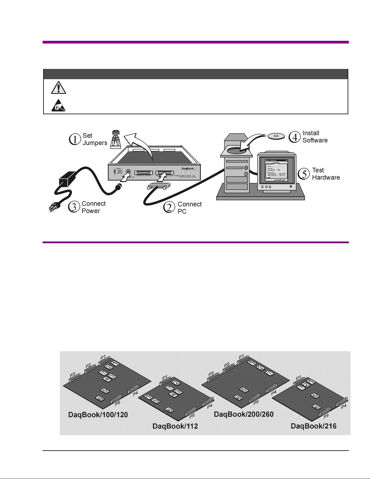
DaqBook Installation Steps, Pictorial Overview
(1) Set Jumpers
1. Place the unit on a flat, stable surface. Ensure n o power or signal lines are connected.
2. Remove cover screw(s), and slide the to p cover plate free of the device. All jumpers are accessi ble from above the board, and no
further disassembly is required.
3. Set jumpers JP1 through JP4 as needed for your application. Jumper configuration options follow shortly. Note that jumpers are
clearly labeled on the actual motherboards.
DaqBook/200, /216, and /260 do not have JP3 and JP4 jumpers. For those units, related settings are made via software.
4. Leave JP5, JP6, and JP7 in their default positions. JP5 (Time Base Selection) default position is for 1 MHz. JP6 (Watchdog Timer
Enable/Disable) default position selects “disabled.” JP7 concerns calibration. See user’s manual prior to changing the settings of
these three jumpers.
5. Replace and secure the cover before applying power and signals.
Motherboard Jumper Locations
Note that DaqBook/112 and DaqBook/216 boards are physically smaller than the other boards.
457-0941, rev 1.2
1-10-00
DaqBook Quick Start Guide 1- 3
Page 12
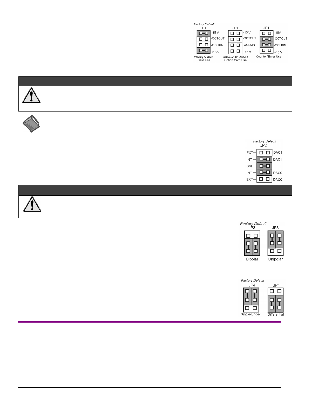
JP1 -
External Analog Expansion Power
If analog option cards (DBKs) are used
+15 and -15 VDC to the cards.
If using a DBK32A or DBK33 Power Supply Card
If no cards are being used
shown in the right-side figure.
, the counter/timer CTR0 is available, and JP1 must be set as
, JP1 jumpers are set to provide
, remove all jumpers from JP1.
&$87,21
Placing the jumpers on -OCTOUT and -OCLKIN could damage the 8254 timer chip!
Supply or a DBK33 Triple-Output Power Supply Card is used, the JP1 shunt jumpers must be removed, otherwise timer chip
damage will occur. Refer to the DBK32A, DBK33, and Power Management sections of your user’s manual for more
information.
Reference Notes:
*
proper steps for installing internal cards. (2) DBK cards and modules are available for a variety of data acquisition functions. Specific DBK
information can be found in your
programming-related information.
JP2 -
JP2 selects an
JP2 also selects
DBK2, DBK4, DBK5, DBK7, DBK17, DBK50, or DBK51.
Leave these jumpers at the factory default. Consult the user’s manual prior to making changes.
DAC Reference Voltage and SSH (Simultaneous Sample and Hold)
Internal
(default) or
SSH
(default) for applications using one or more of the following:
(1) DaqBook/260 is shipped with an additional instruction guide detailing the removal of its slide-out drawer and the
External
Daq User’s Manual
reference voltage for the two separate analog outputs.
(CD, or hard-copy version). (3) Your CD contains power management, software, and
If either a DBK32A Auxiliary Power
&$87,21
Incorrect jumper placement can damage the DaqBook!
JP2 – If EXT DAC0 or EXT DAC1 are used, the SSH jumper must be removed! See users manual for details.
•
JP3 and JP4 - Placing JP3 [or JP4] jumpers horizontally can damage DaqBook!
•
JP3 -
JP3 selects
Note
JP4 -
JP4 selects the analog input lines as 16
or 8 pairs of
If using DBK cards
If you are not using DBK cards and you want differential channels, then position the jumpers for Differential.
Note
(2) Connect PC
1. Verify DaqBook’s power switch is in the “0” (
2. Connect the female-end of the supplied cable to DaqBook’s connector labeled, “
3. Connect the male-end of the cable to an available parallel port on the PC.
4. Connect the supplied AC-to-DC adapter’s jack-end to DaqBook’s
5. Connect the adapter’s plug to a standard AC outlet.
Bipolar or Unipolar A/D Operation
Bipolar
(default) or
•
If using DBK cards
•
If you want 0-10V range
position JP3 jumpers to select
: For DaqBook/200, /216 and /260 a JP3 equivalent setting is made in software.
Unipolar
, leave these jumpers in the factory default positions.
operation for the A/D converter.
[instead of –5 V to +5 V]
Unipolar
.
and are not using DBK cards
Single-ended or Differential Analog Input Channels
Single-Ended
Differential
: For DaqBook/200, /216 and /260 a JP4 equivalent setting is made in software.
channels.
, leave these jumpers in the factory default positions.
and
channels (default);
(3) Connect Power
OFF
) position.
FROM PC PARALLEL PORT
POWER IN
connector.
,
.”
1-4 DaqBook Quick Start Guide
1-10-00
457-0941, rev 1.2
Page 13
6. To verify connections, turn ON the power switch by rotating the rocker-arm switch to the “1” position. The
light up.
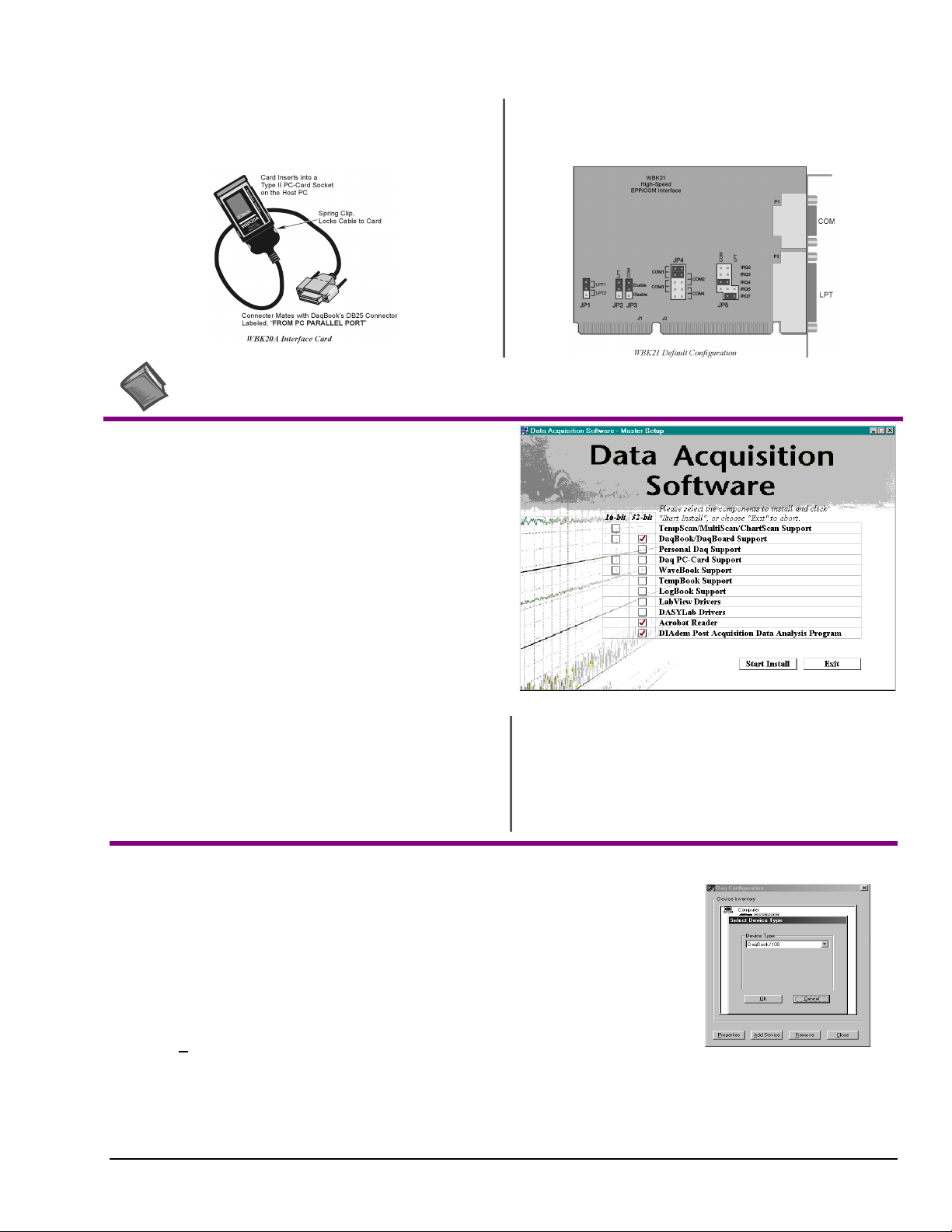
If connecting your DaqBook to a notebook PC
WBK20A, PCMCIA Interface Card. Refer to separate instruction s
(supplied with the WBK20A) if applicable.
, you can use a
If connecting your DaqBook to a desktop PC (with no available
EPP port),
instructions (supplied with the WBK21) if applicable.
you can use a WBK21 Interface card. Refer to separate
POWER LED
should
Reference Note:
consult the Power Management Section of your user’s manual before doing so.
It is possible to use a different VDC power source (instead of the adapter); however, you should
(4) Install Software
Remove previous version Daq* drivers, if present. You can do
1.
this through Microsoft’s Add/Remove Programs feature by
navigating from your desktop as follows:
Start ⇒ Settings ⇒ Control Panel ⇒ Add/Remove Programs
Place the Data Acquisition Software CD in the host PC’s
2.
CD-ROM drive.
may take a few moments, depending on your PC.
3.
If a Licensing Agreement appears, read over the agreement,
then click “Agree.” The Data Acquisition Software Master
Setup Screen appears (see figure at right).
Select
4.
5.
DaqBook/DaqBoard Support.
For Windows95/98/NT
If using Windows3.1, or DOS,
If you do not have Acrobat Reader version 3.0 or greater
installed on your PC, select
enable you to read and print documentation that is included
on the install CD-ROM.
Wait for PC to auto-access the CD. This
(or more recent Windows), select
select
Acrobat Reader
instead of 32-bit.
16-bit
. This will
32-bit
.
6.
Select
DIAdem Post Acquisition Data Analysis
Program
. Refer to your separate DIAdem document
(p/n 457-0903) for information regarding DIAdem.
7. Click “
8. Follow screen prompts.
Start Install
.”
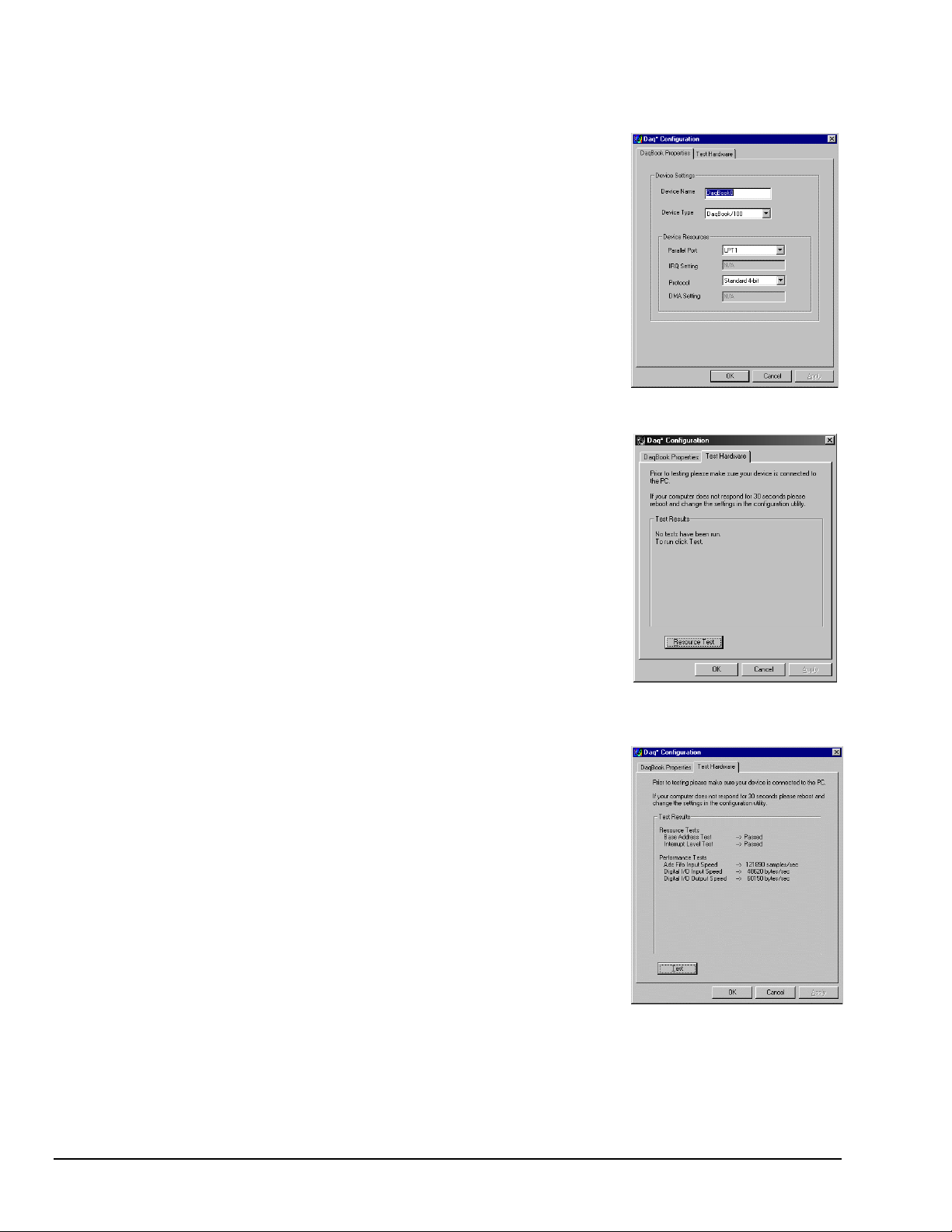
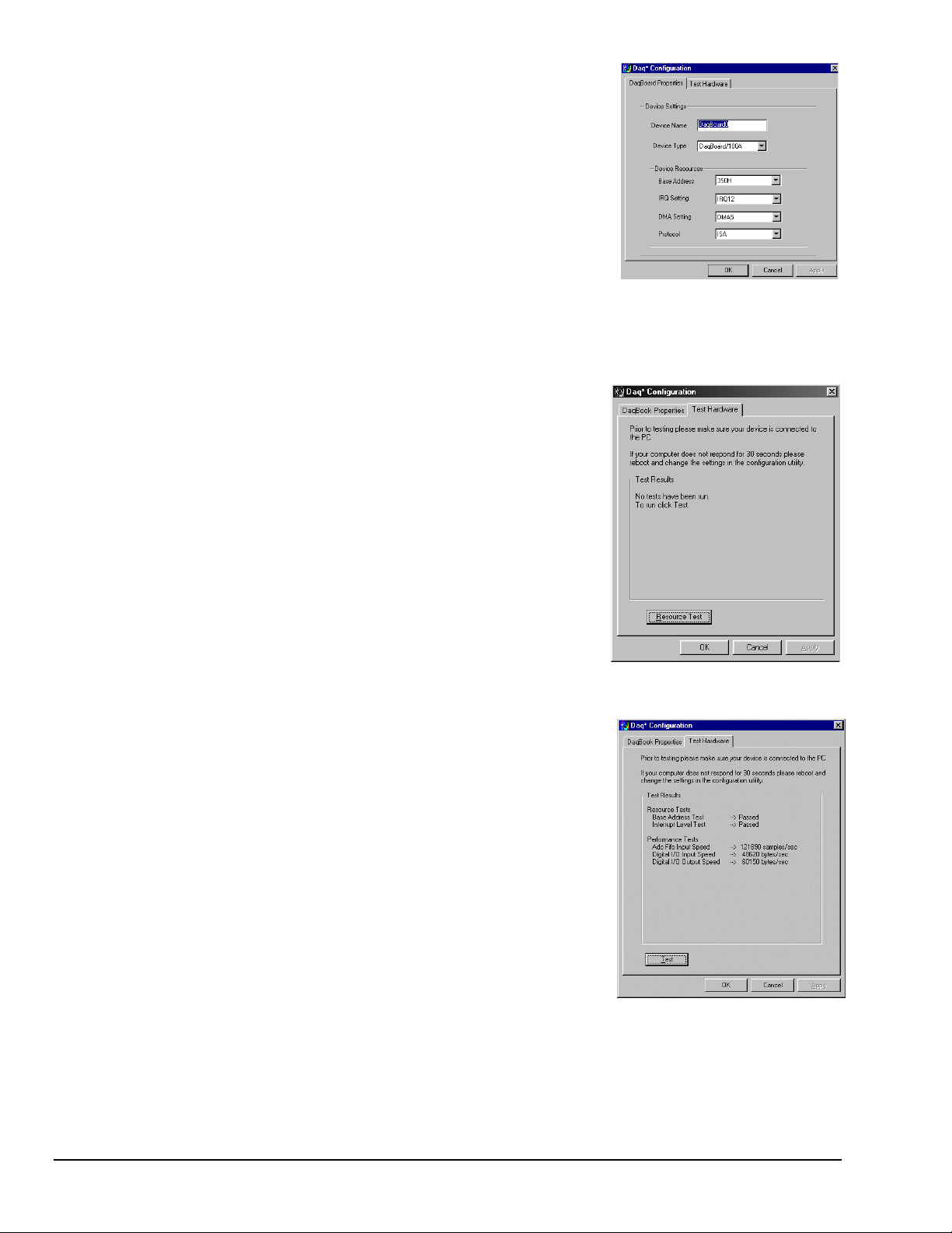
(5) Test Hardware
1. Run the
2. Click “
3. Select your DaqBook model from the “
4. Select your DaqBook from the “
5. Ensure settings are correct, and make changes if needed.
6. Select the
7. Verify DaqBook has been properly installed and powered-on. Make sure the parallel port cable
Click the “
8.
Click the
9.
Test results should be displayed within a few seconds.
Note that test results have two components:
457-0941, rev 1.2
Daq Configurati o n
Add Device
Test Hardware
is firmly in place on both th e DaqBook and the host PC’s LPT port.
Test
.”
Resource Test
button.
control panel applet.
Device Type
Device Inventory
tab.
” button. This begins the test on DaqBook.
Resource Tests
1-10-00
” scroll box and click OK.
” window and click “
and
Properties
Performance Tests.
.”
Each is described below.
Device Type Window
DaqBook Quick Start Guide 1- 5
Page 14
Testing the DaqBook device may, in some cases, cause the system to hang. If test results are not displayed in 30 seconds or the
Note:
system does not seem to be responding, reboot the system. Upon power-up, re-enter the Daq Configuration and change the
DaqBook configuration settings to those that work properly.
Resource Tests
Resource tests are intended to test system capability for the current device configuration. These
tests are pass/fail. Resource test failure may indicate a lack of resource availability or a resource
conflict.
Tests the base address for the selected parallel port. Failure of this test
–
Base Address Test
may indicate that the parallel port is not properly configured within the system. See relevant
operating system and computer manufacturer’s documentation to correct the problem.
Interrupt Level Test
this test may indicate that the parallel port may be currently unable to generate the necessary
hardware interrupt, while other parallel port devices may work OK in this mode. Some parallel
port devices (such as printers) do not require interrupts to work properly. See relevant operating
system and computer manufacturer’s documentation to correct the problem.
Tests the ability of the parallel port to generate interrupts. Failure of
–
DaqBook Properties Tab
Performance Tests
Performance tests are intended to test various DaqBook functions with the current device
configuration. These tests give quantitative results for each supported functional group. The
results represent maximum rates at which the various operations can be performed. These rates
depend on the selected parallel port p rotocol and will vary according to port hardware capabilities.
tests the maximum rate at which data can be transferred from the
–
ADC FIFO Input Speed
DaqBook’s internal ADC FIFO to computer memory through the parallel port. Results are given
in samples/second, where a sample (2 bytes in length) represents a single A/D value.
Digital I/O Input Speed
from the DaqBook’s Digital I/O ports to computer memory through the parallel port. Results are
given in bytes/second.
Digital I/O Output Speed
transferred from the computer’s memory to the DaqBook’s Digital I/O ports through the parallel
port. Results are given in bytes/second.
tests the maximum rate at which DIO input data can be transferred
–
tests the maximum rate at which DIO output data can be
–
Test Hardware Tab
Test Results
If you experience difficulties, please consult your user documentation (on CD, or hardcopy) before calling technical support.
Note:
User documentation includes troubleshooting, as well as a great deal of information regarding specific DBK cards and modules.
1-6 DaqBook Quick Start Guide
1-10-00
457-0941, rev 1.2
Page 15

DaqBoard
ISA Type
[
]
Quick Start Guide
For DaqBoard/100A, /112A, /200A, and 216A
Reference Notes:
applicable to your acquisition system. Specific DBK information can be found in your
install CD-ROM). (3) The user’s manual contains power management, hardware, software, and program-related information.
Turn off power to the host PC and externally connected equipment prior to removing the PC’s cover and
installing a DaqBoard. Electric shock or damage to equipment can result even under low-voltage
conditions.
Take ESD precautions (packaging, proper handling, grounded wrist strap, etc.)
Use care to avoid touching board surfaces and onboard components. Only handle boards by their edges (or
ORBs, if applicable). Ensure boards do not come into contact with foreign elements such as oils, water, and
industrial particulate.
(1) Consult your PC owner’s manual as needed. (2) Be sure to read about the DBK cards and modules
&$87,21
This document does not apply to DaqBoard/2000.
Daq User’s Manual
(included on your
(1) Configure Board
JP1 -
If analog option cards (DBKs) are used
JP1 jumpers are set to provide +15 and -15 VDC to the cards.
If using a DBK32A or DBK33 Power Supply Card
from JP1.
If no cards are being used
must be set as shown in the figure.
JP2 -
JP2 selects an
JP2 also select s
DBK2, DBK4, DBK5, DBK7, DBK17, DBK50, or DBK51.
Leave the JP2 jumpers at their factory default settings.
Consult the user’s manual prior to making changes.
External Analog Expansion Power
&$87,21
Placing the jumpers on JP1’s OCTOUT and -OCLKIN could damage the 8254 timer chip!
Auxiliary Power Supply or a DBK33 Triple-Output Power Supply Card is used, the JP1 shunt jumpers must be removed,
otherwise timer chip damage will occur. Refer to the DBK32A, DBK33, and Power Management sections of your user’s
manual for more information.
,
, remove all jumper s
, the counter/timer CTR0 is available, and JP1
DAC Reference Voltage and SSH (Simultaneous Sample and Hold)
&$87,21
In regard to JP2, the SSH jumper must be removed if you are using EXT DAC0 or EXT DAC1.
See users manual for details.
Internal (default
SSH (default
External
) or
) for applications using one or more of the following:
reference voltage for the two separate analog outputs.
If either a DBK32A
457-0942, rev 1.2
01-11-00
DaqBoard [ISA Type] Quick Start Guide 1-7
Page 16
JP7
Calibration
–
Leave JP7 in default position. Only use JP7 during calibration.
See user’s manual
.
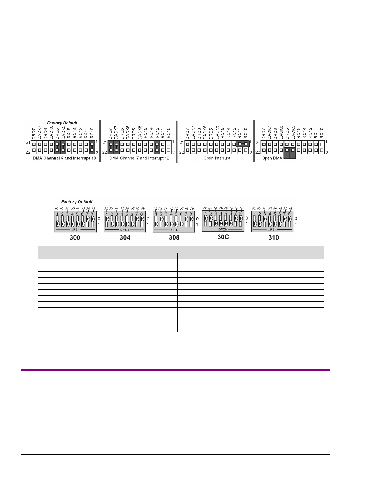
JP8 –
Interrupt Selection
DMA and Interrupt
. DaqBoard may be set to interrupt the PC when certain hardware conditions occur. The interrupt may
be set to IRQ level 10, 11, 12, 14 or 15. DaqBoard’s IRQ level cannot be shared with another device. To disable interrupt
assistance and background transfers you can configure JP8 to “Open Interrupt” (see following figure).
DMA Selection
. Direct Memory Access (DMA) configuration provides for:
(a) high-speed data transfer from the ADC FIFO, or
(b) high-speed data transfer to the DAC FIFO.
Only DMA channels 5-7 (of an ISA AT machine’s seven channels) are available to DaqBoard.
Set DRQ and DACK jumpers to the desired DMA channels. Note that DaqBoard does not share DMA channels.
Set the DMA jumpers to OPEN when other devices will be using DMA channels 5, 6 and 7.
- Base Address
SW1
SW1’s factory default is 300 Hex. If 300 Hex presents an address conflict, set a new SW1 address within the range of
1FF to 3FF (256 to 1023 Decimal). Note that the address must be on a 4-byte boundary.
Industry Standard I/O Addresses
Hex Range Device Hex Range Device
000-1FF Internal system 368-36B PC network (high address)
200-207 Game I/O 36C-36F Reserved
20C-20D Reserved 378-37F Parallel pri nter port 1
21F Reserved 380-38F SDLC, bisynchronous 2
278-27F Parallel pri n t er port 2 390-393 Reserved
2B0-2DF Alternate enhanced graphics adapt er 3A0-3AF Bisynchronous 1
2E1 GPIB (Adapter 0) 3B0-3BF Monochrome display and printer adapter
2E2 & 2E3 Data acquisition (Adapter 0) 3C0-3CF Enhanced graphics adapter
2F8-2FF Serial port 2 3D0-3DF Col or/Graphics monitor adapter
300-31F Protot ype card 3F0-3F7 Diskette Controller
360-363 PC network (low address) 3F8-3FF Seri al port 1
364-367 Reserved
Notes:
(1) SW1’s addres s must be unique, i.e., not used by another device.
(2) I/O addresses, hex 000 to 0FF, are reserved f or system board I/O.
(3) Hex 100 to 3FF are available on the I/O channel.
(4) Although the above table represents i ndustry standards, som e systems may vary.
(2) Make Board Connections
Before connecting your DaqBoard, you should review the following co nnector descr iptions.
P1 Analog I/O
outputs, and various signals for driving expansion cards.
P2 Digital I/O
operation, for P2 expansion cables
. Provides 16 analog input channels, 2 analog output channels, a 16-bit counter/timer, 4 TTL inputs and
. Provides three 8-bit TTL programmable I/O ports and external interrupt input. To ensure reliable
do not exceed 14 inches per attached DBK card
.
P3 Frequency I/O
1-8 DaqBoard [ISA Type] Quick Start Guide
. Provides five 16-bit counters and 16 high-speed digital inputs and external interrupt input.
01-11-00
457-0942, rev 1.2
Page 17
1. Turn power OFF to the PC and all attached equipment.
2. Remove the PC’s cover. Refer to your PC Owner’s Manual as needed.
3. Choose an empty 16-bit ISA slot. Loosen and remove the screw at the top of
the slot’s blank adapter plate. Then slide the plate up and out to remove.
Refer to your PC Owner’s Manual as needed.
4. Align DaqBoard’s edge-connector with the desired ISA slot, and with the
PC’s corresponding rear-panel slot. Gently press the board into the ISA slot.
5. Secure the board by inserting the rear-panel adapter-plate screw.
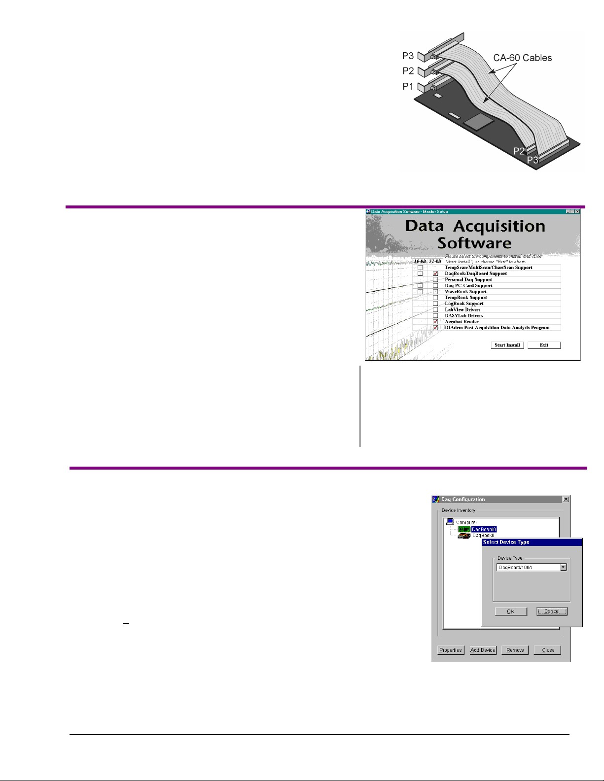
6. If using P2, P3, or both, route CA-60 cables as needed. Secure the P2 and
P3 rear panel connectors, as applicable.
7. Replace the computer’s cover.
8. Plug in all cords and cables.
9. Apply power to the PC.
(3) Install Software
Remove previous version Daq* drivers, if present. You can do this through
1.
Microsoft’s Add/Remove Programs feature by navigating from your
desktop as follows:
Start ⇒ Settings ⇒ Control Panel ⇒ Add/Remove Programs
Place the Data Acquisition Software CD in the host PC’s
2.
CD-ROM drive.
This may take a few moments, depending on your PC.
Wait for PC to auto-access the CD.
DaqBoard’s I/O Connectors
If used, P2 and P3 require cable CA-60.
3.
If a Licensing Agreement appears, read over the agreement, then
click “Agree.” The Data Acquisition Software Master Setup Screen
appears (see figure at right).
4. Select
5. If you do not have Acrobat Reader version 3.0 or greater installed
DaqBook/DaqBoard Support.
For Windows95/98/NT
If using Windows3.1, or DOS,
on your PC, select
(or more recent Windows), select
select
Acrobat Reader
. This will enable you to read
instead of 32-bit.
16-bit
32-bit
and print documentation that is included on the install CD-ROM.
6. Select
.
Program.
document (p/n 457-0903) for information
regarding this program.
7. Click “
8. Follow screen prompts.
(4) Test Hardware
Use the following steps to test your DaqBoard. Note that screen captures of the Daq
Configuration window (with DaqBoard Properties and Test Hardware tabs selected)
appear on the next page.
1. Run the
2. Click “
Daq Configuration
Add Device
.”
3. Select your DaqBoard model from the “
4. Select your DaqBoard from the “
5. Ensure settings are correct, and make changes if needed.
6. Select the “
7. Click the “
8. Click the “
Test Hardware”
Resource Test
” button.
Test
control panel applet.
Device Type
Device Inventory
tab.
” button.
” scroll box and click OK.
” window and click “
Properties
DIAdem Post Acquisition DataAnalysis
Refer to your separate DIAdem
Start Install
.”
.”
Test results should be displayed within a few seconds. Note that test results have two
components:
Resource Tests
and
Performance Tests.
Each is described on the
following page.
Testing the DaqBoard device may, in some cases, cause the system to hang. If test results are not
Note:
457-0942, rev 1.2
displayed in 30 seconds or the system does not seem to be responding, reboot the system. Upon
power-up, re-enter the Daq Configuration and change DaqBoard configuration settings to those that
work p roperly.
01-11-00
Device Inventory and
Device Type Windows
DaqBoard [ISA Type] Quick Start Guide 1-9
Page 18
Resource Tests
The resource tests are intended to test system capability for the current device
configuration. These tests are pass/fail. Resource test failure may indicate a lack of
availability of the resource or a possible resource conflict.
Base Address Test - T ests the ba se address for the selected parallel port. Failure of
this test may indicate that the parallel port is not properly configured within the
system. See relevant operating system and computer manufacturer’s documentation
to correct the problem.
Interrupt Level Test - Tests the ability of the parallel port to generate interrupts.
Failure of this test may indicate that the parallel port may be currently unable to
generate the necessary hardware interrupt.
Other parallel port devices may work fine in this mode. Some parallel port
Note:
devices (such as printers) do not require interrupts to work properly. See
relevant operating system and computer manufacturer’s documentation to
correct the problem.
Performance Tests
Performance tests check various DaqBoard functions with the current device
configuration. These tests give quantitative results for each supported functional
group. The results represent maximum rates at which the various operations can be
performed. Note that the rates depend on selected parallel port protocol and will
vary according to port hardware capabilities.
ADC FIFO Input Speed - Tests the maximum rate at which data can be transferred
from the DaqBoard’s internal ADC FIFO to computer memory, through the PC’s
parallel port. Results are given in samples/second, where a sample (2 bytes in
length) represents a single A/D value.
DaqBoard Properties Tab
Digital I/O Input Speed - Tests the maximum rate at which DIO input data can be
transferred from DaqBoard’s Digital I/O ports to computer memory, through the
PC’s parallel port. Results are given in bytes/second.
Digital I/O Output Speed – Tests the maximum rate at which DIO output data can be
Test Hardware Tab
transferred from the computer’s memory to DaqBoard’s Digital I/O por ts, through
the PC’s parallel port. Results are given in bytes/second.
Test Results
If you experience difficulties, please consult your user documentation before calling for technical support. Note that
Note:
the user documentation includes a troubleshooting chapter, as well as a great deal of information regarding specific
DBK cards and modules.
1-10 DaqBoard [ISA Type] Quick Start Guide
01-11-00
457-0942, rev 1.2
Page 19
Daq PC-Cards
Quick Start Guide
For Daq/112B and Daq /216B
This guide provides basic installation instructions for Daq PC-Cards. You may need to refer to additional material, such as
that contained in the user’s manual (included on your installation CD).
Note: Daq PC-Cards are not used with Windows NT operating systems.
Daq PC-Cards for notebook PCs comply with PC Card Standard Specification 2.1, PCMCIA Type II (5mm). Input power
for the Daq PC-Card comes from the host computer. The PC-Cards do not provide output power; thus power for DBK
signal conditioning cards and modules must be provided by another source, such as a CDK10 (powered/2-slot expansion
chassis). The CDK10 contains two expansion slots, power adapter, and rechargeable nickel-cadmium battery. Other
expansion options, such as three or ten slot chassis (DBK60 and DBK41, respectively) can connect to a PC-Card via cable.
All three chassis allow you to add additional DBK cards to the acquisition system. Refer to your user’s manual for detailed
information regarding the CDK10, DBK cards and modules.
Reference Notes:
(1) Daq PC-Cards plug into a PCMCIA Type II slot. Consult your Notebook PC owner’s manual as needed.
(2) Daq PC-Cards can connect to DBK cards or modules through an interface cable. Be sure to read about the
DBK cards and modules applicable to your acquisition system. Specific DBK information can be found in your
Daq User’s Manual (included on the install CD-ROM). A wide variety of expansion options exists.
(3) The Daq User’s Manual contains power management, hardware, software, and program-related information.
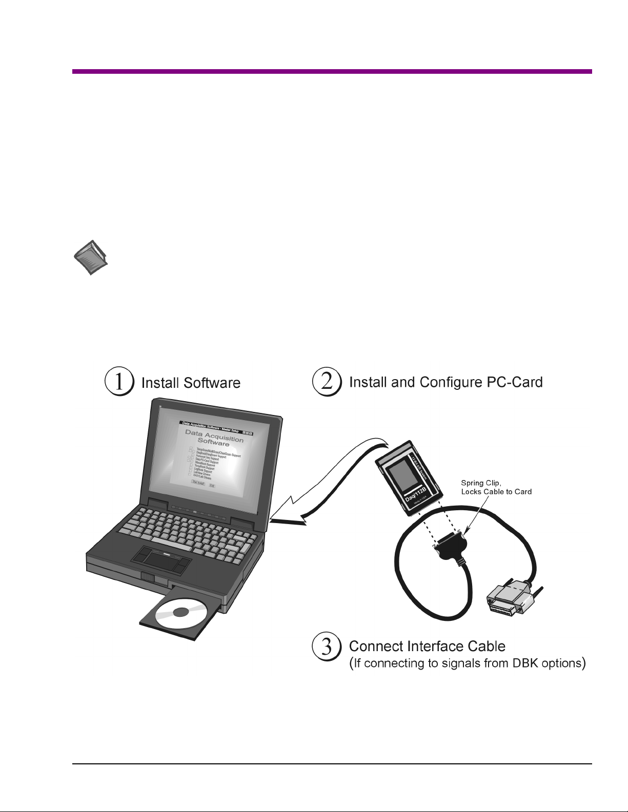
PC-Card Installation, A Pictorial Overview
457-0943, rev 1.2
05-11-00
Daq PC-Cards Quick Start Guide 1-11
Page 20

(1) Install Software
Remove previous version Daq* drivers, if present. You can do this through Microsoft’s
1.
feature by navigating from your desktop as follows:
Place the Data Acquisition Software CD in the host PC’s CD-ROM drive.
2.
This may take a few moments, depending on your PC.
3. If a Licensing Agreement appears, read over the agreement, then click “Agree.” The Data Acquisition
Software Master Setup Screen appears (see following figure).
4. On the Master Setup Screen, select
If using DBK Cards, Windows3.1, or DOS, select
5. If you do not have Acrobat Reader version 3.0 or greater installed on your PC, select
This will enable you to read and print documentation that is included on the install CD-ROM.
6. Select
7. Click “
8.
DIAdem Post Acquisition Data Analysis Program
(p/n 457-0903) for information regarding this program.
Start Install
Follow screen prompts
.”
.
Daq PC-Card Support
Start ⇒ Settings ⇒ Control Panel ⇒ Add/Remove Programs
Wait for PC to auto-access the CD.
.
; otherwise select 32-bit.
16-bit
. Refer to your separate DIAdem document
Add/Remove Programs
Acrobat Reader
.
: If using DBK Cards, Windows3.1,
Note
or DOS, select 16-bit;
otherwise select 32-bit.
Selecting Daq PC-Card Support, Acrobat Reader, and DIAdem
(2) Install and Configure the PC-Card
Install the PC-Card
1. Ensure the Notebook PC is powered on.
2. Insert the Daq PC-Card into the Notebook PC’s PCMCIA slot.
3. Push the Daq PC-Card into the PCMCIA slot until the card makes full contact.
When the card properly engages you should hear a click and see the PC’s
socket-eject button extended.
4. A “New Hard ware Found” window should appear. You are now ready to
configure the card.
Insert this end of card into
the PCMCIA slot.
1-12 Daq PC-Cards Quick Start Guide
01-11-00
457-0943, rev 1.2
Page 21

Configure the PC-Card
Note: All Daq PC-Card configuration is made through software; however, you may need to set jumpers or
switches in DBKs or other system components. DBK configuration is detailed in the user’s manual
included on your CD.
☛
For Windows 95/98/ME Operating Systems
Windows 95/98/ME operating systems include Card and Socket Services and do not require any additional
PCMCIA software. The supplied software CD includes a Windows 95/98/ME configuration file with the
driver.
After the “New Hardware Found” window appears:
1. Select the option labeled, “Driver from disk supplied by hardware manufacturer”.
2. Click “OK”.
3. Follow the screen prompts.
Navigate from the desktop as follows, to determine system resources used by the Daq PC-Card.
Start Menu
Settings
Control Panel
System
Device Manager
Data Acquisition Icon
PCMCIA
Resources
After navigating as described, the Base Addr and the IRQ (interrupt) settings for the Daq PC-Card should
appear. There are currently two possible Daq PC-Cards; Daq/112B and Daq/216B. You can change the
interrupt [or address] of a Daq PC-Card as follows:
a) Go into the Properties screen.
b) Select Resources.
c) “Uncheck” the “Use automatic settings” check box.
d) Highlight the interrupt [or address] setting to be changed.
e) Select “Change settings.”
Note: It is possible to configure Daq PC-Cards as “non-standard” devices.
Non-standard device configuration is discussed in your user’s manual.
☛
For DOS and Windows 3.x Operating Systems
When used with DOS or Windows 3.x, the Client Driver or Enabler will need to be loaded onto your
system. This software facilitates changing the IRQ level, Communication Port/Socket #, and Base Address
settings, as needed.
DaqView does not support Interrupt 9 in 16-bit applica tions. If Windows 95/98/ME installs the Daq
PC-Card at Interrupt 9, then the interrupt must be changed under System, Device Manager as described in
steps a through e, above. Note that some computers have sound card s whose resources ar e not accounted for
in the system file (e.g., ThinkPad 755).
Daq PC-Cards are shipped with Client Driver and Enabler files that conform to the PCMCIA (PC Card)
Card Services Specification 2.1. When used with CardSoft Card and Socket Services or compatible
software, a Daq PC-Card will automatically configure itself at system start-up. Use of CardSoft is not
required, but the chosen software must be compatible with the PCMCIA (PC-Card) Card Services
Specification 2.1.
The Client Driver or Enabler sets the IRQ, Communication Port/Socket # (if more than one PCMCIA
socket is available), and an Address Range. These settings become the “default”. Depending on your
system configuration, these default settings may conflict with the IRQ, Communication Port/Socket #, and
457-0943, rev 1.2
05-11-00
Daq PC-Cards Quick Start Guide 1-13
Page 22

Address Range that your system has already allocated to another device. Consult your user’s manual if this
is the case, or if you desire more control of your software configuration.
(3) Connect the Interface Cable
Digital I/O is supported and includes four general-purpose digital inputs and four general-purpose digital
outputs. The PC can access these TTL-level digital I/O lines when the Daq PC-Card is not transferring data
from the A/D converter. These I/O lines are not available if using P1 expansion cards or DBKs.
Daq/112B PC-Card, before and after attaching to a CA-134 Interface Cable
The CA-134 Interface Cable provides a female DB37 (P1) port for connecting a single passive DBK device
(such as DBK11 or DBK40) to the PC-Card. An included gender changer (CN-86, not shown) provides a
means of interfacing with a CA-37-x expansion cable. The CN-86 gender changer is also used when
connecting the PC-Card to a CDK10 module. Your user’s manual contains more detailed information,
including a pin-out of the DB37 (P1) interface.
Damage to the card or cable may result if not properly connected! Never force the connection. The
Daq PC-Card and cable are keyed, and should connect easily when properly oriented. Make sure the
connectors sli de together at a level angle. Exce ssive or angular force can damage the connectors.
Follow these steps to connect the Daq PC-Card to the Interface Cable (CA-134).
1. Hold the Daq PC-Card so that the label is face up and the bottom edge is facing yo u.
2. Verify key alignment is correct for the card and the cable.
3. Depress the cable’s spring-clips and connect the cable to the PC-Card.
4. After connection is made, release the spring-clips.
Connecting to DBK Modules
Only DBK modules that support the DB37 (P1) connector can be used with Daq PC-Cards. If connecting
to a CA-37-x expansion cable, or to a CDK10 module, use the supplied gender changer (CN 86). Refer to
your user’s manual as needed.
1. Plug the DB37 (P1) connector end of the Interface Cable into the compatible DBK module.
2. Verify all connections before powering up the system.
1-14 Daq PC-Cards Quick Start Guide
01-11-00
457-0943, rev 1.2
Page 23

Overview 2
Daq Systems, the Modular Concept …… 2-1
DaqBooks, DaqBoards, and Daq PC-Cards …… 2-3
Using DBK Cards and Modules for Signal Conditioning ……2-4
Daq Software ……2-6
Tips on Setting Up a Data Acquisition System ……2-7
Daq Systems, the Modular Concept
Daq equipment and software form a modular, interrelated family of products that provide great flexibility in
data acquisition system design. This flexibility allows for the development of custom systems that are
unique to the user, and which can be optimized for his or her specific application needs. With the Daq
product line, system expansion or redesign can typically be accomplished with relative ease. The following
table shows the relation among the three main categories of Daq-related products:
•
Primary Acquisition Device. This is the main data acquisition device, e.g., a DaqBook, DaqBoard,
or Daq PC-Card. These devices provide a vital data conversion and communications link between
the data source of transducers and signal conditioners and the data processor of the host computer.
•
DBK Option Cards and Modules. Over 30 DBK cards and modules (the number is constantly
growing) provide various types of signal conditioning and system expa nsion. Note that certain DBK
modules exist for the purpose of supplying power to other members of the acquisition system. The
DBK options are discussed in a separate chapter that is included [in pdf format] on your installation
CD.
•
Software. DaqView out-of-the-box software provides a graphical user interface with easy to read
spreadsheet formats for viewing channel data, as well as a choice of analog, digital, and bar-graph
meters. Waveform analysis can be performed, when applicable. Post data analysis can be performed
with the DIAdem program. More information is included in the software-specific chapters (also
included on your install CD). Note that, in addition to the included out-of-the-box software, Daq
products can be controlled via user-written custom progr a ms thro ugh Applications Program Interface
(API). Several languages are supported, e.g., C/C++, VisualBASIC, Delphi. See the separate
programmer’s manual (1008-0901) for program-related information.
DaqBook / DaqBoard [ISA] / Daq PC-Card User’s Manual
10-18-00
2-1
Page 24

Daq Data Acquisition Devices
Category Device Description
Primary
Acquisition
Device
DBK Option
Cards and
Modules
Software
DaqBook
DaqBoard/2000 Series
(see note 1)
DaqBoard (ISA types)
Daq PC-Card
Analog Signal
Conditioning
Analog Output
Digital I/O and Control
Expansion
Connections
Power Supply DBKs: 30A, 32A, 33, 34; CDK10
Included Software DaqView, DIAdem-View, Visual Basic extensions,
Optional Software DaqView/2000, DaqViewXL, DASYLab
Portable Data Acquisition Modules
12-bit: DaqBook/100, /112, /120
16-bit: DaqBook/200, /216, /260
Plug-In Boards for PCI Bus-Slots
Six boards identified as /2000 through / 2005
Plug-In Boards for ISA Bus-Slots
12-bit: DaqBoard/100A, /112A
16-bit: DaqBoard/200A, /216A, /2000
Plug-In PCMCI Card
12-bit: Daq/112B
16-bit: Daq/216B
Cards and modules used to condition Analog Signals
DBK/ 4, 7, 8, 9, 12, 13, 15, 17, 18, 19, 42, 43A, 44, 45, 50, 51, 52, 53, 54,
207, 207/CJC
Cards used to modify Analog Output Signals
DBK/ 2, 5
Cards and modules used to condition Digital I/O
DBK/ 20, 21, 23, 24, 25, 208
Cards and modules used to expand the acquisition system.
DBK/ 1, 10, 11A, 35, 40, 41, 60, 200, 201, 202, 203, 204, 205, 206, 209
Application Programming Interface (API)
Note 1: DaqBoard/2000 Series Boards are covered in the separate document, DaqBoard/2000 Series
User’s Manual, p/n1033-0901.
2-2
10-18-00
DaqBook / DaqBoard [ISA] / Daq PC-Card User’s Manual
Page 25

DaqBooks, DaqBoards and Daq PC-Cards
Daq*s connect to one or more DBKs on their signal input side and a computer on their output side. Each
Daq type connects to the computer in a different way:
•
The DaqBook is an external module that connects to a computer’s enhanced parallel port (EPP)
interface or PC-Card link.
•
The DaqBoard [ISA type] is an internal card that plugs into an ISA-bus slot within a computer.
•
The DaqBoard/2000 Series boards plug into a PCI-bus slot within a computer.
•
The Daq PC-Card is inserted in the PCMCIA slot of a notebook computer.
Features common to the Daq*s include:
•
100-kHz channel-to-channel scan and gain switching (10 µs); 200-kHz for the DaqBoard/2000.
•
512-location sequence memory that can be loaded with any combination of channels and gains.
•
Ability to access up to 256 different channels of DBK signals while maintaining the channel-tochannel scan rate. The DBK expansion options can accommodate mixed-signal inputs from
thermocouples and RTDs to isolated high-voltage inputs and strain gages.
•
Ability to handle 8 differential or 16 single-ended signal inputs without DBK expansion units.
•
Ability to handle fixed digital I/O up to 4 TTL lines in and 4 TTL lines out (accessible only if no
analog expansion cards are in use).
Each type of Daq has several models to meet various needs. The table lists these models and their features.
Daq* Models and Features
Model
DaqBook Models
DaqBook/100 12 bit 2 Jumper Jumper 16 high speed
DaqBook/112 12 bit 2 Jumper Jumper N/A N/A 8.5×11
DaqBook/120 12 bit 2 Jumper Jumper 16 high speed
DaqBook/200 16 bit 2 Software Software 16 high speed
DaqBook/216 16 bit 2 Software Software N/A N/A 8.5×11
DaqBook/260 16 bit 2 Software Software 16 high speed
DaqBoard Models, ISA Type
DaqBoard/100A 12 bit 2 Sequencer Software 16 high speed
DaqBoard/112A 12 bit 2 Sequencer Software N/A N/A 4.5×13. 125 970 mA
DaqBoard/200A 16 bit 2 Sequencer Software 16 high speed
DaqBoard/216A 16 bit 2 Sequencer Software N/A N/A 4.5×13. 125 1340 mA
Daq PC-Card Models
Daq/112B 12 bit N/A Bipolar
Daq/216B 16 bit N/A Bipolar
A/D
Resolution
Analog
Output
Channels
Unipolar/
Bipolar
Selection
Only
Only
Single-
ended/
Differential
Selection
Software N/A N/A 3.375×0.2 510 mA
Software N/A N/A 3.375×0.2 510 mA
Programmable
Digital I/O
Lines
24 gen purpose
24 gen purpose
24 gen purpose
24 gen purpose
24 gen purpose
24 gen purpose
Program
mable
Counter/
Timers
5 ch
7 MHz
5 ch
7 MHz
5 ch
7 MHz
5 ch
7 MHz
5 ch
7 MHz
5 ch
7 MHz
Size
(inches)
8.5×11
×1.375
×1.375
8.5×11
×1.375
8.5×11
×1.375
×1.375
11×13
×3.5
4.5×13.125 1330 mA
4.5×13.125 1700 mA
Current
Use
510 mA
360 mA
510 mA
620 mA
600 mA
620 mA
DaqBook / DaqBoard [ISA] / Daq PC-Card User’s Manual
10-18-00
2-3
Page 26

Using DBK Cards and Modules for Signal Conditioning
The DBK signal-conditioning units are designed for use with the Daq devices; however, the DBKs can be
used with ISA or PCI bus-based data acquisition boards from other vendors. The DBKs perform best when
used with an acquisition device that can dynamically select channel, gain, and range. Dynamic channel and
gain/range selection allow for high channel-to-channel scan rates with a variety of transducers.
DBK output signals can be bipolar, e.g., -5 to +5 V, or unipolar, e.g., 0 to 10 V. The user can select a range
of relevant values to correspond to the lowest signal (e.g., -5 or 0 V) and the highest signal (e.g., 5 or 10 V)
signal. This type of range selection guarantees the highest resolution in 12-bit or 16-bit conversion.
DBK modules share the same footprint as the DaqBook and a typical notebook PCs; allowing for
convenient stacking. The majority of these modules have their own power supply.
Several options exist for packaging and powering the DBKs and are discussed later in this chapter
The following table lists the DBKs by function. Note that the DBK Option cards and Modules
chapter describes each DBK in detail.
2-4
10-18-00
DaqBook / DaqBoard [ISA] / Daq PC-Card User’s Manual
Page 27

DBK Option Cards and Modules
Product Name/Description Capacity Signal
Connectivity
Analog Signal Conditioning
DBK4 Dynamic Signal Input Card 2 channels P1
DBK7 Frequency-to-Voltage Input Card 4 channels P1
DBK8 High-Voltage Input Card 8 channels P1
DBK9 RTD Measurement Card 8 channels P1
DBK12 Low-Gain Analog Multiplexing Card 16 channels P1
DBK13 High-Gain Analog Multiplexing Card 16 channels P1
DBK15 Universal Current/Voltage Input Card 16 channels P1
DBK16 Strain-Gage Measurement Card 2 channels P1
DBK17 Simultaneous Sample & Hold Card 4 channels P1
DBK18 Low-Pass Filter Card 4 channels P1
DBK19 High-Accuracy Thermocoupl e Card 14 channels P1
DBK42 5B Isolated Signal-Conditi oni ng Module 16 c hannel s P1
DBK43A Strain-Gage Meas urement Module 8 channels P1
DBK44 5B Isolated Signal-Conditi oni ng Card 2 channels P1
DBK45 SSH and Low-Pass Filter Card 4 channels P1
DBK50 Isolated High-Voltage Input Module 8 channels P1
DBK51 Isolated Low-Voltage Input Module 8 channels P1
DBK52 Thermocouple Input Module 14 channels P1
DBK53 Low-Gain Analog Multiplexing Module 16 channel s P1
DBK54 High-Gain Analog Multiplexing Module 16 channels P1
DBK207 Carrier Board for 5B Compatible A nal og Input Modules. 16 channels Two P1s
DBK207/CJC Carrier Board for 5B Compatible Analog Input Modules .
DBK207/CJC includes c ol d junction compensati on (CJC).
16 channels Two P1s
P4
P4
*
Analog Output
DBK2 V ol tage Output Card 4 channels P1
DBK5 Current Output Card 4 channel s P1
Digital I/O / Control
DBK20 General-Purpose Digital I/O Card (Screw Term i nal s) 48 channels P2
DBK21 General-Purpose Digital I/O Card (DB37 Connec t ors) 48 channels P2
DBK23 Optically Isolated Digital -Input Module 24 channels P2
DBK24 Optically Isolated Digital -Out put Module 24 channels P2
DBK25 Relay Output Card 8 channels P2
DBK208 Carrier board for Opto-22 Compatible Solid-State-Relay
Digital Modules.
Two 8-bit banks of
SSR modules
Two P2s
P4
Expansion and Connection
DBK1 16-Connector BNC Adapter Module 16 connectors P1
DBK10 3-Slot Expansion Chassis 3 cards P1, P2, or P3
DBK11A Screw-Terminal Option Card (DB37-Screw Terminal Block) Component
sockets
DBK40 BNC Interface 18 connectors P1 or P3
DBK41 Analog Expansion Enclosure 10 cards P1 or P2
DBK60 Expansion Chassis with Termination P anel s 3 cards P2
DBK200 P4-to-P1 Adapter Board P1 P4
DBK201 P4-to-P1/P2/P3 Adapter Board P1, P2, P3 P4
DBK202 P4-to-P1/P2/P3 Adapter Board with Screw-Terminals P1, P2, P3 P4
DBK203 A module version of DBK202 P1, P2, P3 P4
DBK204 A module version of DBK202 with an included CE cable k i t. P1, P2, P3 P4
DBK205 P4-to-TB1 12-slot Screw Terminal Block for DaqBoard/2003. TB1, 12-slot P4
DBK206 P4-to-P1/P2/P3 Adapter Board with Screw-Terminals P1, P2, P3 P4
DBK209 P4-to-P1/P2/P3 Mini-Adapter Board P1, P2, P3 P4
P1
P1, P2, and P3 do not exist on the DaqBoard/2000 Series boards, but are obtained by use of the P4 adapters
(DBK200 series). These adapters typically connect to the DaqBoard/2000 series 100-pin P4 connector via
cable. The DBK200 series boards are detailed in the DBK chapter. Note that the DBK chapter is included
on your install CD in pdf format, as a stand-alone document.
DaqBook / DaqBoard [ISA] / Daq PC-Card User’s Manual
10-18-00
2-5
Page 28

Daq Software
The Daq devices have software options capable of handling mo st applications. Three types of software are
available:
•
ready-to-use graphical programs, e.g., DaqView, DaqViewXL, and DIAdem
•
drivers for third-party, icon-driven software such as DASYLab and LabView
•
various language d rivers to aid cust om programming using API
Ready-to-use programs are convenient for fill-in-the-blank applications that do not require programming for
basic data acquisition and display:
•
DaqView is a Windows-based program for basic set-up and data acquisition. DaqView lets you
select desired channels, gains, transducer types (including thermocouples), and a host of other
parameters with a click of a PC’s mouse. DaqView lets you stream data to disk and display data
in numerical or graphical formats. PostView is a post-acquisition waveform-display program
within DaqView.
•
DaqViewXL allows you to interface directly with Microsoft Excel to enhance data handling and
display. Within Excel you have a full-featured Daq control panel and all the data display
capabilities of Excel.
•
DIAdem-View lets you view, measure and edit your data.
•
The Daq Configuration control panel allows for interface configuration, testing, and
troubleshooting.
Each Daq system comes with an Application Programming Interface (API). API-language drivers include:
C/C++, Delphi, and Visual Basic. The latest software is a 32-bit version API.
Reference Note:
Programming topics are covered in the Programmer’s User Manual (1008-0901). A
pdf-formatte d version of the programmer’s manual is included on your installation CD.
2-6
10-18-00
DaqBook / DaqBoard [ISA] / Daq PC-Card User’s Manual
Page 29

Tips on Setting up a Data Acquisition System
Prior to designing or setting up a custom data acquisition system, you should review the following tips.
After reviewing the material you can write out the steps you will need to follo w to setup a system that will
best meet your specific application needs.
1. The end use of the data can affect how you set up and program you acquisition system. Prior to
creating the system you should determine channel assignments, and lay out the whole system. If you
can answer the following questions you are off to a good start. If not, you need to find the answers.
•
What units, ranges, sampling rates, etc. are best for your data?
•
Will the data be charted graphically, statistically processed, or exported to other programs?
•
How will your data be used?
•
How will the data be saved?
•
What are your system’ power requirements? Using several DBKs or transducers that require
excitation current may require an extra power supply, e.g., a DBK32A.
2. Assign channel numbers.
3. Plan the location of transducers, cable runs, DBKs, the Daq device, and the computer. Label your
transducers, cables, and connectors to prevent later confusion.
4. When configuring your Daq device(s) consider t he following:
•
The DaqBook and DaqBoard (ISA type) have internal jumpers and switches that you must set
manually to match yo ur ap plication.
•
Some DaqBook models are partially configured in software.
•
Daq PC-Card are configured entirely in software.
•
DaqBoard/2000 Series boards are PCI type boards. They have no jumpers or switches and are
configured ent irely through software.
•
You may need to refer to other documentation, such as Quick Starts, Installation Guides, and
pertinent DBK documentation.
5. Remember to configure all the DBK cards and modules for your application. Several jumpers and DIP
switches may need to be set (channel, gain, filters, signal mode, etc).
6. Perform all hardware configurat ions before connecting signal and power.
7. Route and connect all signal and power cables while all power is turned OFF.
8. To minimize electrical noise, route all signal lines away from any RF or high-voltage devices.
9. Follow your device’s specific installation instructions. For certain devices software should be installed
first; for others, hardware should be installed prior to software installation.
10. After software is loaded, remember to set the software parameters as needed for your application. The
software must recognize all the hardware in the system. Measurement units and ranges should be
checked to verify that they meet your application requirements.
11. Remember to set all channels to the proper mode for your DBK or other signal source.
12. After your system is up and running, verify proper data acquisition and d ata storage.
13. Verify system accuracy; adjust ranges or calibrate as needed.
DaqBook / DaqBoard [ISA] / Daq PC-Card User’s Manual
10-18-00
2-7
Page 30

Device specific information regarding system setup and expansion can be found in the Daq hardware
chapters and in the DBK chapter. You may need to read the DBK10/41/60 sections for system expansion
and the DBK30A/32A/33 and the CDK10 sections for power management.
Since DBK modules are controlled by the Daq sequencer, external channels can be scanned at the same
high speed as internal channels. Each main (base) channel can support up to 16 sub-channels and thereby
provide expansion up to 256 input channels. DBK cards and modules can be daisy-chained off the P1
connector of the Daq or expansion module. DBKs add another level of multiplexing and programmable
gain to each channel. Setting up channel parameters often requires both hardware and software setup.
Modules for packaging DBK expansion cards are available with 3 slots (DBK10) or 10 slots (DBK41)—
some DaqBooks also have expansion slots. The best option depends on the number of DBK cards in your
system. For just a few cards, use the stackable 3-slot DBK10 low-profile expansion enclosure. For more
than six cards, use the 10-slot DBK41. Multiple DBK41s can be daisy-chained to handle a large number of
DBKs in a system. For termination panel connections, use the DBK60 expansion chassis or DaqBook/260,
which is a combination of the DaqBook/200 and DBK60.
Additional power supplies (essential with the Daq PC-Card) may be needed to handle the load. The DBK
power options accommodate a wide range of applications from laboratory to automotive and other field
applications. The power systems can use any 10 to 20 VDC source or an AC source with the included
adapter. For portable applications, the compact DBK30A rechargeable power supply can provide power to
the DBK10 or DBK41. The DBK30A also includes a 28 V output for powering 4 to 20 mA transducers.
For applications with many DBK cards (initially or in future expansion), the DBK32A or DBK33 can be
installed into any expansion slot. The DBK32A provides ±15 VDC and the DBK33 provides ±15 VDC
and +5 VDC.
2-8
10-18-00
DaqBook / DaqBoard [ISA] / Daq PC-Card User’s Manual
Page 31

Daq* Hardware 3
DaqBook/100,/112,/120,/200, and /216 ……3-1
Front and Rear Panels ……3-2
Jumpers ……3-3
Connections ……3-6
DaqBook/260 …… 3-11
Front and Rear Panels ……3-11
Hardware Setup ……3-12
DaqBoard/100A,/112A,/200A, and /216A ……3-16
Switches and Jumpers ……3-17
Connections ……3-20
DaqBook/100, /112, /120, /200, and /216
The DaqBook module is enclosed in a 8.5” × 11” × 1.375” metal box external to the computer,
(11” × 13” × 3.5” for the DaqBook/260). The DaqBook attaches to a PC’s parallel port via 25-wire parallel
port cable and can transfer data bi-directionally at up to 170 Kbytes/s for a standard printer port (SPP) and
up to 800 Kbytes/s for an enhanced parallel port (EPP). Data is stored in the PC’s memory and hard drive,
not in the DaqBook.
Input power for a DaqBook can come from various sources (e.g., a 12 V car battery, the included
AC adapter, or a rechargeable nicad battery module). This power flexibility is ideal for portable and remote
data acquisition, such as automotive and aviation in-vehicle testing.
Output power from the P1 connector includes +5 VDC (pin 1) and ±15 VDC (pins 21 and 2). The section
External Analog Expansion Power (JP1) explains how to set JP1 based on power use in the system. Also,
refer to the section Power Management at the beginning of chapter 7, DBK Options Cards and Modules.
DaqBooks have capabilities that previously required several plug-in DAS boards. All DaqBooks provide
16 analog inputs (expandable up to 256), 2 analog outputs, and 4 digital inputs and outputs. Some models
have built-in expansion slots; other models have additional digital I/O and counter/timer capabilities.
•
The DaqBook/112 and /216 models provide 1 slot for an expansion DBK card.
•
The DaqBook/100, /120, and /200 models do not have the expansion slot but do have 24 generalpurpose digital I/O channels (expandable up to 192), 16 high-speed digital inputs, and 5
frequency/pulse I/O channels.
Daq PC-Card ……3-23
Configuration ……3-23
Connections ……3-27
System Expansion Examples ……3-29
T-Cable Guide ……3-29
Note: The /120 adds an EPP port capability to the /100.
Note: The /260 has 3 expansion slots for DBK cards.
The various DaqBook models have either 12-bit or 16-bit binary resolution.
•
12-bit models include model #s /100, /112, and /120.
•
16-bit models include model #s /200, /216, and /260.
Analog input capabilities are very flexible. The A/D maximum sample rate is 100 kHz (divide by number
of channels for scan rate) with a 16-channel multiplexer and a pr o grammable-gain input amplifier. Users
can expand channel capacity to 256 analog inputs via expansion modules for multiplexing RTDs,
thermocouples, strain gages, anti-aliasing filters, and simultaneous sample and hold amplifiers. Expansion
cards and modules attach to the P1 I/O connector (refer to Connector Pinouts later in this chapter).
P1 (DB37 interface) is compatible with multiplexers and signal conditioners from several manufacturers.
The DaqBooks perform 100 kHz scan sequences with programmable delays from 10 µs to 10 hours. The
100 kHz conversion rate fixes the time skew between channels at 10 µs. The 512-location scan sequencer
allows selection of the input amplifier gain for each channel. The DaqBook/100, /120, /200, and /260 can
scan 16 digital inputs in the same sequence used for analog inputs (such inputs are thus time-correlated).
Optional simultaneous-sample-and-hold (SSH) cards enable DaqBooks to sample up to 256 channels at the
same instant. Scanning and timing specifications are met even with a full complement of expansion
modules. All types of transducers are scanned within the same scan group without PC intervention.
DaqBooks offer a wide selection of triggering capabilities. The scan can be triggered by software, a TTL
signal, or an analog input level (including slope). The analog input trigger is hardware-based and
minimizes trigger latency to less than 10 µs.
DaqBook/DaqBoard/Daq PC-Card User’s Manual
10-18-00
3-1
Page 32

DaqBook/100, /112, /120, / 200, /216 Daq* Hardware
P
s
1
S
r
P
p
A
x
x
1
C
A
C
1
1
C
D
c
+5+
-
H
S
&
T
S
Signal
I/O
P1
ANALOG I/O
(DAS-16
compatible)
P2*
DIGITAL I/O
(PIO-12
compatible)
P3*
PULSE/FREQ.
HIGH-SPEED
DIGITAL I/O
(CTM-05
compatible)
8 DE/16 SE
analog input
multiplexer
4 digital outputs
for high-speed
channel expansion
4 general purpose
digital outputs
4 general purpose
digital inputs
1 auxiliary counter gate
1 TTL trigger input
2 gain select for expansion
Dual 12-bit DAC
24-bit general purpos e
digital I/O lines
16 high-speed
digital inputs
5 counter/timer
channels
*Models /100, /120, /200, and /260 only
**Models /112, /120, /200, and /216 only
-or-
-or-
512-step, random access
channel/gain sequencer
GA
1, x2
4, x8
er channel
rigger
elect
nalog Triggeromparator
ample
old
equencer
eset
timebase.
DaqBook Block Diagram
mplifier
2 or 16-bit,
00 kHz, A-to-D
onverter
00kHz
lock
rogrammable
equencer
0 us to 12 hrs
C-DC
15
15
onverter
(+7-20 VDC for /100, /112, and /120)
(+9-18 VDC for /200)
(+10-24 VDC for /216)
4K word
FIFO
data
buffer
VDC
Power In
Computer
I/O
P4
to PC
parallel
port
or EPP*
P5
pass-through
to printer
Front and Rear Panels
The following figures show the location of controls and connectors on the DaqBook exteriors. These
locations vary by model (DaqBook/100, /120, and /200 versus the DaqBook/112 and /216).
P1 - ANALOG I/O P2 - DIGITAL I/O P3 - FREQUENCY I/O
Front Panel of DaqBook/100/120/200
Rear Panel of DaqBook/100/120/200
P1 - ANALOG I/O
Front Panel of DaqBook/112/216
Rear Panel of DaqBook/112/216
3-2
10-18-00
DaqBook/DaqBoard/Daq PC-Card User’s Manual
Page 33

Daq* Hardware DaqBook/100, /112, /120, /200, /216
DaqBook Controls and Connectors
Switch
POWER Depressing the “1” side of this rocker-arm switch turns t he power on.
Connectors
POWER INPUT This DIN5 input connector accepts +7 to 20 VDC for the /100, /112, /120;
TO PARALLEL PRINTER This port allows the computer to use any s tandard parallel printer in a
FROM PC PARALLEL PORT This port connects to t he computer’s standard or enhanced paral l el port
P1 - ANALOG I/O Provides sixteen analog input channels, two analog output channels,
P2 - DIGITAL I/O Provides three 8-bit TTL programmable I/O ports and external interrupt input
P3 - FREQUENCY I/O Provides five 16-bi t counters and sixteen high-speed digital i nputs and
Indicators
POWER This LED lights when power is applied to the DaqB ook and the power switch
P1-P2-P3 ACTIVE This LED lights when the DaqBook is i n an active state. This LED i s off
BUFFER OVERRUN This LED lights for a buffer overrun error. This occurs when A/D s i gnal s are
A/D ACTIVE This LED lights during an A/D s can sequence. If the sequence has a low
+10 to 24 VDC for the /216; +9 to 18 VDC f or the /200, /260.
pass-through mode (DB25).
(DB25).
two 16-bit counter/timers , four TTL inputs and outputs, and various signals
for driving expansion cards (DB37).
(DB37).
external interrupt input (DB37).
is in the “1” (ON) position.
when the DaqBook is disabled or in the print er-pass-through mode. P1,
P2, and P3 are software access i bl e from the computer.
converted faster than the PC collects the data. Depending on t he
application, this indication may not be an error.
number of steps and occurs inf requent ly, t his indicator will only flash
briefly.
Jumpers
Proper installation requires that several jumpers and switches be set correctly for your application. These
jumpers and switches are located inside the DaqBook enclosure and possibly on your DBKs. Jumpers for
the various DaqBook models are configured similarly except for the jumpers’ relative locations. Silkscreening on the motherboard identifies jumpers and switches. Note: Even if using the default settings, you
should verify actual jumper positions.
The DaqBook configuration jumpers include:
•
JP1 - External Analog Expansion Power
•
JP2 - DAC Voltage Reference
•
JP3* - Unipolar/Bipolar
•
JP4* - Differential/Single Ended
•
JP5 - Time Base
•
JP6 - Watchdog Timer Enable
•
JP7 - Calibration (refer to Chapter 12, Calibration)
* The DaqBook/200, /216, and /260 do not have JP3 and JP4 jumpers—these settings are made via
software.
DaqBook/DaqBoard/Daq PC-Card User’s Manual
Location of DaqBook Jumpers
10-18-00
3-3
Page 34

DaqBook/100, /112, /120, / 200, /216 Daq* Hardware
External Analog Expansion Power (JP1)
This 4×2 header (JP1) has 3 possible settings. If analog option cards (DBKs) are used, the JP1 pins are set
to provide +15 and -15 VDC to the cards. If such cards are not used, the counter/timer CTR0 is available,
and JP1 must be set accordingly. The default setting is for use of analog option cards.
&$87,21
If using a DBK32A Auxiliary Power Supply or a DBK33 Triple-Output Po wer Supply
Card, the JP1 shunt jumpers must be entirely removed. Placing the jumpers on
-OCTOUT and -OCLKIN will damage the 8254 timer chip. Refer also to the Power
Management section in the chapter DBK Option Cards and Modules.
JP1
-15 V
-O C TOU T
-O C L K IN
+15 V
Counte r/Time r Use
(16-bit Mod e O nly)
JP1
-15 V
-O C TOU T
-O C L K IN
+15 V
Analog Option
Card Use
JP1
-15 V
-O C TOU T
-O C L K IN
+15 V
DBK32A or DBK33
Option Card Use
JP1 External Analog Expansion Settings
DAC Reference Selection (JP2)
This 5×2 header (JP2) allows you to select internal or external voltage references for the two separate
analog outputs. If the internal -5 VDC reference is selected, either DAC can output from 0 to +5 VDC as
the register count varies from 0 to 4095 (12-bit). If an external voltage reference is desired (up to +10 VDC
or –10 VDC), the shunt jumpers must be set accordingly. There is also a provision to allow the outputting
of a simultaneous Sample-Hold command signal on the DAC1-REFIN pin with the DAC1 set up for an
internal reference.
&$87,21
The SSH setting cannot be used at the same time as a DAC1 external reference due to a
potentially damaging conflict on P1 pin #26. The defaults are both DAC0 and DAC1 set
to Internal Reference.
EXT
IN T
SSH
INT
EXT
DAC0 External Ref
DAC1 External Ref
3-4
Note: The SSH setting is used with DBKs: 2, 4, 5, 7, 17, 50, and 51. Refer to the DBK chapter (4) as
needed.
JP2
DAC1
DAC0
DAC0 External Ref
DAC1 Internal Ref
JP2 JP 2 JP2
DAC0 Internal Ref
DAC1 External Ref
DAC0 Internal Ref
DAC1 Internal Ref
JP2 DAC Reference Settings
10-18-00
Factory Default
JP2
DAC0 Internal Ref
DAC1 Internal Ref
w ith SSH
DaqBook/DaqBoard/Daq PC-Card User’s Manual
DAC0 External Ref
DAC1 Internal Ref
w ith SSH
JP2
Page 35

Daq* Hardware DaqBook/100, /112, /120, /200, /216
Bipolar or Unipolar A/D Operation (JP3)*
*Hardware Setting For DaqBook/100, /112, and /120 Only
The A/D converter in the DaqBook can be operated in two modes, bipolar or unipolar. In the bipolar mode
(default setting), input voltages up to ±5 VDC can be applied (on the ×1 gain range). In the unipolar mode,
positive voltages up to 10 VDC may be applied (×1 gain range). Refer to the table below for gain, range,
and mode relations.
&$87,21
JP3 is a double-wide jumper that must be positioned vertically. Misplacing this jumper
in a horizontal position will damage the unit.
Gain Mode Volts Range
×1BI ±5
×2BI ±2.5
×4 BI ±1.25
×8 BI ±0.625
×1 UNI 0 to +10
×2 UNI 0 to +5
×4 UNI 0 to +2.5
×8 UNI 0 to +1.25
JP3 Unipolar/Bipolar Operation Settings
Note: For the DaqBook/100, /112, and /120, set the jumpers to the desired position as shown in figure.
Note: For the DaqBook/200, /216, and /260 the Unipolar/Bipolar option is selected via software by the
daq200SetMode and daq200SetScan commands.
Single-ended or Differential Analog Input Channels (JP4)*
*Hardware Setting For DaqBook/100, /112, and /120 Only
&$87,21
JP4 must be positioned vertically. Positioning JP4 ho rizontally will damage the unit.
JP4 Single-Ended/Differential Settings
JP4 is a 3×2 header used to configure the 16 analog input lines as 16 single-ended channels or as 8 pairs of
differential channels. In general, if the DaqBook is going to be used in the stand-alone mode (no analog
expansion cards), either mode can be used. If analog expansion cards (each DBK capable of
sixteen single-ended or differential inputs) are used, the single-ended mode must be used. The default
setting is thus single-ended. Place the jumpers in the desired position (see figure).
Note: For the DaqBook/200, /216, and /260, the Unipolar/Bipolar option is selected via software by the
daq200SetMode and daq200SetScan commands.
DaqBook/DaqBoard/Daq PC-Card User’s Manual
10-18-00
3-5
Page 36

DaqBook/100, /112, /120, / 200, /216 Daq* Hardware
Time Base Selection (JP5)
JP5 is a 2×3 header that allows you to apply 1 of 3 oscillatorderived frequencies to the 8254 timer chip. The frequencies are
100 kHz, 1 MHz, and 10 MHz. The default setting is 1 MHz.
Note: A special-version 8254 timer-chip is required for 10 MHz.
DaqView and most 3rd party software assume the 1 MHz
time base.
JP5 Time Base Settings
Watchdog Timer Enable/Disable (JP6)
This 3-pin header (JP6) allows the elective use of the watchdog timer. The
watchdog timer is used to assure consistent operation o f the pass-through print er
port during data collect i on and to restore pass-through printing if the computer is
reset. Enable the watchdog timer if you:
•
Use a printer on the pass-through printer por t
•
Expect the computer to be suddenly reset during DaqBook operation
•
Want the DaqBook to reset itself rather than having to manually toggle the
DaqBook’s power switch.
Place the shunt jumper in the desired position as shown in the figure. The default
JP6 Watchdog Timer
Settings
setting is Disabled.
Connections
Note: The watchdog timer can mistake a computer pause for a reset and then impede background
measurements. For this reason, the watchdog timer should normally be disabled unless automatic
restoration of pass-through pr inting is required.
The DaqBook connects to the computer’s parallel printer port (female DB25) with the supplied cable (CA35-2). Connect the male end to the computer and the female end to the DaqBook connector labeled FROM
PC PARALLEL PORT. Any printer port (LPT1, LPT2, or LPT3) may be used but should be noted for
software setup. When using a printer, attach the original printer cable (male DB25) into the DaqBook
connector labeled TO PARALLEL PRINTER.
Note: Printing cannot occur during data acquisition.
The DaqBook may be powered with a supplied AC adapter that plugs into any standard AC wall outlet. An
isolated VDC source of 1-2 amps may also be used. Power requirements are +7-20 VDC for the
DaqBook/100/112/120, +10-24 VDC for the DaqBook/216, and +9-18 VDC for the DaqBook/200/260.
Before pl uggi ng unit in, make sure the power switch is in the “0” (OFF) position.
•
If using an AC power adapter, plug it into an AC outlet and attach the low voltage end to the jack on
the DaqBook.
•
If using another VDC source, make sure leads are connected to the proper DIN terminals.
3-6
10-18-00
DaqBook/DaqBoard/Daq PC-Card User’s Manual
Page 37

Daq* Hardware DaqBook/100, /112, /120, /200, /216
AC
AC
Power
Adapter
Power
Source
Power
Switch
+
GND
+V
Printer
Optional
Power Input
Conn ector
Com puter
CA-35-2
DaqBook
DaqBook Connections
To verify connections, turn ON the power switch by flipping the rocker- switch to the “1” position, and the
POWER LED should light up. If using a printer, check operation by issuing a <PRINT SCREE N> or
equivalent command.
Note: Software installation is necessary before the DaqBook can perform any functions.
Parallel Port Capabilities
The DaqBook/112, /120, /200, /216, and /260 (but not the /100) models can take advantage of enhanced
parallel port (EPP) communication. Standard LPT ports on an IBM-compatible PC have 4-bit and 8-bit
modes to read data from the printer port. The 8-bit mode is faster than the 4-bit, but not all printer ports
support this mode. EPP ports are parallel ports with additional hardware that allows the DaqBook to
communicate with the PC faster (3 to 10 times) than standard parallel ports.
EPPs require special hardware, and only certain computers are EPP-capable. Most laptop computers that
use the Intel 386SL or 486SL chip set (which includes the 82360 I/O controller) are EPP-capable. For
computers with plug-in card slots, EPP adapter cards are available. You may wish to consult your computer
documentation for details about your machine and possible adapter cards. For more information about
supported EPP hardware and machine-specific issues, refer to the README file supplied with the software.
Note: The EPPs may be configured for any available I/O address but must be configured for either
interrupt 5 or 7. The DaqBook driver does not support the use of interrupts 10, 11, 12, or 15.
In addition to supporting the special hardware required for EPP capability, some computers and parallel
port cards come equipped with special BIOS or device drivers which support the EPP BIOS Draft Revision
3 (and possible Draft Revision 5) standard. This standard specifies a software level interface between
applications and the EPP hardware itself. The DaqBook/DaqBoard software driver supports computers and
parallel ports equipped with EPP BIOS Draft Revision 3.
Connector Pinouts
To gain access to DaqBook port connectors, signals can be connected via a CA-37-x cable through a
D-shell 37-pin female connector or a DBK11 screw-terminal card with component sockets.
The following tables detail P1, P2, and P3 pinouts and how each line is used.
DaqBook/DaqBoard/Daq PC-Card User’s Manual
10-18-00
3-7
Page 38

DaqBook/100, /112, /120, / 200, /216 Daq* Hardware
N
N
N
N
N
I
I
I
I
N
I
I
C
D
V
5
1
-
/
T
3
1
U
R
S
S
O
H
H
W
0
C
C
P
/
/
R
V
T
5
+
C
1
2
G
/
1
3
3
P
P
P
I
O
O
6
5
3
4
D
N
)
T
V
G
5
U
-
0
1
R
(
O
S
S
G
/
1
P
I
7
E
0
F
0
W
A
E
/
A
O
/
R
D
P
V
D
8
0
1
9
1
1
I
H
H
4
5
1
1
H
N
H
I
C
C
*
*
C
/
/
*
F
/
N
N
I
I
E
N
I
R
O
O
L
7
H
C
2
1
O
O
L
L
L
5
4
6
H
H
H
C
C
C
C
3
4
5
1
1
1
I
H
3
1
H
C
*
/
N
I
L
3
H
C
6
1
N
I
H
2
1
H
C
*
/
N
I
O
O
L
2
H
C
7
1
N
I
I
I
I
I
I
I
H
H
H
H
0
1
1
H
H
C
*
/
N
I
O
L
1
H
H
C
8
1
D
8
1
9
N
H
H
G
C
C
*
*
/
/
E
N
N
I
I
S
N
O
E
L
S
0
L
L
9
1
DaqBook
6
3
P1 Pinout
Analog I/O
(compatible with
Metrabyte DAS-16)
3
1
0
2
2
2
2
2
2
0
C
T
U
V
O
5
1
2
+
/
N
R
I
P
T
0
K
C
C
O
L
C
0
R
T
C
E
S
S
D
T
A
H
H
R
G
C
C
/
/
T
/
0
0
2
0
P
R
P
0
A
I
/
T
D
C
/
/
2
H
P
S
I
S
7
6
2
2
2
T
D
N
0
I
U
N
G
F
O
I
G
E
1
L
L
R
L
L
A
1
/
D
2
5
4
Pin Signal Name Description for P 1 P i n Use
1+5 PWR
2 CTR 0 OUT/-15 VDC
+5 V supply (Refer to
Counter 0 output (8254 chip)/ -15 V supply (Refer to
Power Management
section in chapter 7)
3 OP 3/CHS 3 Digital out bit 3/channel select line for expansion cards
4 OP 1/CHS 1 Digital out bit 1/channel select line for expansion cards
5 IP 3/GS 1 Digital in bit 3/gain select line for expansion cards
6 IP 1/GS 0 Digital in bit 1/gain select line for expansion cards
7 POWER GND Digital ground
8 VREF (-5V) -5 V supply @ 10 mA max
9 D/A 0 OUT Digital to analog converter output ch 0
10 D/A 0 REF IN Digital to analog converter referenc e i n ch 0 (must invert)
11 CH 7 LO IN/CH 15 HI IN Ch 7 LO IN (differential mode)/ch 15 HI IN (single-ended mode)
12 CH 6 LO IN/CH 14 HI IN Ch 6 LO IN (differential mode)/ch 14 HI IN (single-ended mode)
13 CH 5 LO IN/CH 13 HI IN Ch 5 LO IN (differential mode)/ch 13 HI IN (single-ended mode)
14 CH 4 LO IN/CH 12 HI IN Ch 4 LO IN (differential mode)/ch 12 HI IN (single-ended mode)
15 CH 3 LO IN/CH 11 HI IN Ch 3 LO IN (differential mode)/ch 11 HI IN (single-ended mode)
16 CH 2 LO IN/CH 10 HI IN Ch 2 LO IN (different i al mode)/ch 10 HI IN (single-ended mode)
17 CH 1 LO IN/CH 9 HI IN Ch 1 LO IN (different i al mode)/ch 9 HI IN(single-ended mode)
18 CH 0 LO IN/CH 8 HI IN Ch 0 LO IN (different i al mode)/ch 8 HI IN (single-ended mode)
19 L.L. GND Low-level ground (analog ground - use with analog inputs and outputs)
20 CTR 2 OUT Counter 2 output (8254 chip)
21 CTR 0 CLOCK IN/+15 VDC
Counter 0 clock in (8254 chip)/+15 V supply (Refer to
22 OP 2/CHS 2 Digital output bi t 2/ channel select line f or expansion cards
23 OP 0/CHS 0 Digital output bi t 0/channel select line f or expansion cards
24 IP 2/CTR 0 GATE Digital input bit 2/counter 0 gate (16-bit support only)
25 IP 0/TRIG 0 Digital i nput bit 0/trigger 0
26 D/A 1 REF IN/SSH Digital-to-analog converter reference in ch 1 (must invert)/ SSH
27 D/A 1 OUT Digital-t o-anal og converter output ch 1
28 L.L. GND Low-level ground (analog ground - use with analog inputs and outputs)
29 L.L. GND Low-level ground (analog ground - use with analog inputs and outputs)
30 CH 7 HI IN Ch 7 HI IN (single-ended mode or differential mode)
31 CH 6 HI IN Ch 6 HI IN (single-ended mode or differential mode)
32 CH 5 HI IN Ch 5 HI IN (single-ended mode or differential mode)
33 CH 4 HI IN Ch 4 HI IN (single-ended mode or differential mode)
34 CH 3 HI IN Ch 3 HI IN (single-ended mode or differential mode)
35 CH 2 HI IN Ch 2 HI IN (single-ended mode or differential mode)
36 CH 1 HI IN Ch 1 HI IN (single-ended mode or differential mode)
37 CH 0 HI IN Ch 0 HI IN (single-ended mode or differential mode)
: Software configuration commands determine P1 di gi tal I/O pin functions. Actual shunt-jumper placement is required to provide
Note
±15 VDC to expansion cards or disconnect internal DAC references to allow externally select ed DAC references. Digital I/ O cannot
be used with DBKs. “/” indicates the pin can be used for either functi on but not both at the same ti me.
1
0
9
8
3
3
3
2
2
N
N
N
D
I
I
I
N
I
I
I
H
H
H
H
G
H
C
4
5
6
7
H
H
H
C
C
C
Power Management
Power Management
3
N
N
I
I
I
I
H
3
2
H
H
C
C
3
3
3
N
N
N
I
I
I
I
I
I
H
H
H
1
0
H
H
C
C
7
4
2
5
3
in chapter 7)
in chapter 7)
3-8
10-18-00
DaqBook/DaqBoard/Daq PC-Card User’s Manual
Page 39

Daq* Hardware DaqBook/100, /112, /120, /200, /216
DaqBook
P2 Pinout
E
L
6
7
4
5
3
T
U
P
N
N
E
I
R
R
I
I
P
1
3
2
B
B
B
A
T
T
R
R
O
O
P
P
4
5
B
B
B
T
T
T
R
R
R
R
O
O
O
O
P
P
P
8
6
7
0
2
1
B
B
B
T
T
T
R
O
O
P
P
0
1
9
D
R
D
C
N
/
N
G
N
G
3
2
4
1
1
1
1
1
Digital I/O
This P2 interface is
available on the
DaqBook/100, /120,
/200, and /260.
2
V
5
+
G
3
1
2
0
2
2
2
6
7
D
N
C
C
T
T
T
R
R
R
O
O
O
P
P
P
6
4
5
7
2
2
2
2
1
3
5
2
4
C
C
C
C
C
T
T
T
T
T
R
R
R
R
R
O
O
O
O
O
P
P
P
P
P
Pin Signal Name Description for P2 Pin Use
1 IR INPUT Interrupt line input (no functions to acces s this)
2 IR ENABLE I nterrupt line enable (no functions t o access this)
3 PORT B 7 Digital input/output - port B bit 7
4 PORT B 6 Digital input/output - port B bit 6
5 PORT B 5 Digital input/output - port B bit 5
6 PORT B 4 Digital input/output - port B bit 4
7 PORT B 3 Digital input/output - port B bit 3
8 PORT B 2 Digital input/output - port B bit 2
9 PORT B 1 Digital input/output - port B bit 1
10 PORT B 0 Digital i nput/output - port B bit 0
11 GND Digital ground
12 N/C Pin not connected/not used
13 GND Digital ground
14 N/C Pin not connected/not used
15 GND Digital ground
16 N/C Pin not connected/not used
17 GND Digital ground
18 +5 V
+5 V supply (Refer to
Power Management
section in chapter 7)
19 GND Digital ground
20 +5 V
+5 V supply (Refer to
Power Management
section in chapter 7)
21 GND Digital ground
22 PORT C 7 Digital input/output - port C bi t 7
23 PORT C 6 Digital input/output - port C bi t 6
24 PORT C 5 Digital input/output - port C bi t 5
25 PORT C 4 Digital input/output - port C bi t 4
26 PORT C 3 Digital input/output - port C bi t 3
27 PORT C 2 Digital input/output - port C bi t 2
28 PORT C 1 Digital input/output - port C bi t 1
29 PORT C 0 Digital input/output - port C bi t 0
30 PORT A 7 Digital i nput/output - port A bit 7
31 PORT A 6 Digital i nput/output - port A bit 6
32 PORT A 5 Digital i nput/output - port A bit 5
33 PORT A 4 Digital i nput/output - port A bit 4
34 PORT A 3 Digital i nput/output - port A bit 3
35 PORT A 2 Digital i nput/output - port A bit 2
36 PORT A 1 Digital i nput/output - port A bit 1
37 PORT A 0 Digital i nput/output - port A bit 0
: No local lines are available if digital expansion cards are in use.
Note
1
2
0
9
8
3
3
3
3
2
2
6
4
5
7
0
A
A
A
A
C
T
T
T
T
R
R
O
O
P
P
T
R
R
R
O
O
O
P
P
P
P
D
C
N
/
/
N
G
N
6
5
1
1
1
4
3
5
3
3
1
3
2
A
A
A
T
T
R
R
R
O
O
O
P
P
D
D
C
N
N
5
G
+
G
9
8
7
1
1
6
7
3
3
0
A
T
P2 expansion cables must be kept short for proper operation. Do not exceed 14” per attached DBK card.
DaqBook/DaqBoard/Daq PC-Card User’s Manual
10-18-00
3-9
Page 40

DaqBook/100, /112, /120, / 200, /216 Daq* Hardware
E
E
DaqBook
P3 Pinout
Pulse/Frequency/
E
L
T
B
U
A
P
N
7
5
6
N
E
I
D
R
R
I
I
S
3
2
1
4
4
I
I
D
S
I
I
I
D
D
D
S
S
S
5
7
8
6
0
I
3
2
1
I
I
D
D
D
S
G
S
S
0
1
1
9
1
T
A
N
I
G
5
5
4
D
N
2
1
R
R
R
T
T
T
C
C
C
C
3
5
4
1
1
1
1
E
T
T
A
N
I
G
4
R
R
T
T
C
7
6
1
E
A
T
N
N
I
I
A
G
3
G
2
3
R
R
R
T
T
T
C
C
C
8
9
1
1
High-Speed
Digital I/O
1
2
3
This P3 interface is
available on the
DaqBook/100, /120,
/200, and /260.
1
0
2
2
C
V
/
5
I
N
+
D
S
4
5
2
2
4
5
1
1
I
D
S
S
2
2
2
2
3
1
I
D
S
0
1
2
1
1
1
I
I
I
D
D
D
S
S
S
0
9
8
2
2
2
3
T
9
8
T
I
I
U
U
D
D
O
O
O
S
5
4
C
S
R
R
R
T
T
T
O
C
C
C
7
6
3
Pin Signal Name Description for P3 Pin Use
1 IR INPUT Interrupt line input (used with counters)
2 IR ENABLE Interrupt line enable (us ed with counters)
3 SDI 7 High-speed digit al i nput bit 7 (low byte)
4 SDI 6 High-speed digit al i nput bit 6 (low byte)
5 SDI 5 High-speed digit al i nput bit 5 (low byte)
6 SDI 4 High-speed digit al i nput bit 4 (low byte)
7 SDI 3 High-speed digit al i nput bit 3 (low byte)
8 SDI 2 High-speed digit al i nput bit 2 (low byte)
9 SDI 1 High-speed digit al i nput bit 1 (low byte)
10 SDI 0 High-speed digital input bit 0 (low byte)
11 GND Digital ground
12 CTR 5 GATE Counter 5 gat e (9513 chip)
13 CTR 5 IN Counter 5 input (9513 chip)
14 CTR 4 GATE Counter 4 gat e (9513 chip)
15 CTR 4 IN Counter 4 input (9513 chip)
16 CTR 3 GATE Counter 3 gat e (9513 chip)
17 CTR 3 IN Counter 3 input (9513 chip)
18 CTR 2 GATE Counter 2 gat e (9513 chip)
19 CTR 2 IN Counter 2 input (9513 chip)
20 +5 V
+5 V supply (Refer to
Power Management
section in chapter 7)
21 D IN STROBE NC
22 SDI 15 High-speed digital input bit 15 (hi gh byt e)
23 SDI 14 High-speed digital input bit 14 (hi gh byt e)
24 SDI 13 High-speed digital input bit 13 (hi gh byt e)
25 SDI 12 High-speed digital input bit 12 (hi gh byt e)
26 SDI 11 High-speed digital input bit 11 (hi gh byt e)
27 SDI 10 High-speed digital input bit 10 (hi gh byt e)
28 SDI 9 High-speed digital i nput bi t 9 (high byte)
29 SDI 8 High-speed digital i nput bi t 8 (high byte)
30 OSC. OUT Oscillator output - f out (9513 chip)
31 CTR 5 OUT Counter 5 output (9513 chip)
32 CTR 4 OUT Counter 4 output (9513 chip)
33 CTR 3 OUT Counter 3 output (9513 chip)
34 CTR 2 OUT Counter 2 output (9513 chip)
35 CTR 1 OUT Counter 1 output (9513 chip)
36 CTR 1 IN Counter 1 input (9513 chip)
37 CTR 1 GATE Counter 1 gat e (9513 chip)
4
5
6
3
3
3
3
T
T
T
U
U
U
U
O
O
O
3
2
1
T
R
R
C
T
T
C
C
C
7
3
3
3
T
E
N
I
T
1
A
G
R
1
R
T
3-10
10-18-00
DaqBook/DaqBoard/Daq PC-Card User’s Manual
Page 41

DaqBook/260
The DaqBook/260 is a combination of a DaqBook/200 and a DBK60 expansion chassis. The DaqBook sits on an
upper shelf within the enclosure. Below it, a card drawer can hold three analog DBK cards and provide termination
panels with connectors for various sensors.
P1
External
DB37
J3 conn ec ts
to P 1 o n
DaqBook
interna l cable.
PULSE/FREQ .
HIG H-SPEED
P2
DIGITAL I/O
P3
DIGITAL I/O
by
Pin 1 (+5V)
Interc o nn e ct
37
P1
JP2
Pins
2-37
JP1
J3
P1
Board
24-bit general purpose
digital I/O lines
J1
37
Intern al DB37
Interc o nn e ct B o ar d
8 DE/16 SE
analog input
m ult iplex er
4 digital outputs
for high-speed
channel expansion
4 general purpose
digital outputs
4 general purpose
digital inputs
1 auxiliary counter gate
1 TTL trigger input
2 gain select for ex pansion
Dual 12-bit DAC
16 high-speed
digital inputs
5 counter/tim er
channels
-or-
-or-
1 of 3 user-sup plied
DBK cards (all 3 must
be all analog or all
digital--no mixing)
(1 of 3)
PGA
x1, x2
x4, x8
per channel
512-step, random access
channel/gain sequencer
Trigger
Select
Analog Trigger-In
Comparator
DaqB ook/260 Block Diagram
Am plifier
Sample
&
Hold
Sequencer
reset
Programmable
sequencer
tim e bas e .
10 us to 10 hrs
+5
+15
-15
DC-DC
converter
Vario us
connector
types are
availa ble.
Termination
Panels (3)
16-bit, 100 kHz
Analog-to-Digital
Converter
10 kHz
Clock
512 word
FIFO
data
buffer
Fuse
ON/OFF
Switch
To
Sensors
DB25P
to PC
parallel
port
DB25S
pass-th rough
to printe r
DIN-5
10-20 VDC
Power In
Front and Rear Panels
The front panel has male DB37 connectors for
system expansion via P1, P2, and P3. The DaqBook
section includes a power switch, a DIN-5 connector
for power-in, a DB25 connector for printer passthrough, a DB25 to the PC’s para llel port, and LED
status indicators for power, buffer overload, P1-P2-P3
active, and A/D active.
The rear panel is made of three termination panels with connectors for the various sensors.
DaqBook/DaqBoard/Daq PC-Card User’s Manual
1-14-00
32:(5
32:(5 ,1
9'& 72 9'&
3
72 3$5$//(/35,17(5
)520 3& 3$5$//(/3257
3
'DT%RRN
32:(5 %8))(5 333
29(5581
$&7,9( $&7,9 (
3
70
$'
3-11
Page 42

DaqBook/260 Daq* Hardware
+
-
+
-
10
+
-
+
5
-
+
-
ANA COM--
A
B
C
&+520
$/80(/
.
&+520
$/80(/
.
&+520
$/80(/
.
&+520
&+520
$/80(/
$/80(/
.
.
&+520
&+520
$/80(/
$/80(/
.
.
&+520
$/80(/
.
&+520
$/80(/
.
1 223
0
4 5
5
8
9
13 141415
12
3
6 77
10 11
11
15
ANA COM --
&+520
$/80(/
.
&+520
&+520
$/80(/
$/80(/
.
.
&+520
&+520
$/80(/
$/80(/
.
.
A
BB
C
A
C
1
0
4
9
8
13
12
12
6
10
+
-
2
+
-
4
+
67
-
ANA COM --
A
B
C
Hardware Setup
:$51,1*
Electrical Shock Hazard! To avoid injury or equipment damage, turn off power to all connected
equipment during setup.
&$87,21
Use ESD tools, containers, and procedures during setup of DBK cards. Electrostatic discharge can
damage some of the components.
To prevent pin damage, align DBK cards with the backplane DB37 connectors before gently
pressing them together.
1 – Turn off system power and disconnect DaqBook/260
If the DaqBook/260 is presently connected in a system, turn off all system devices and disconnect it.
2 – Remove top cover
Remove the two top cover screws and slide off the top cover.
3 – Remove card drawer
A. Remove the two screws holding the card drawer to the chassis.
B. Loosen the three captive thumbscrews holding the termination panels to the chassis.
C. Using the handle, carefully slide out the card drawer.
3-12
1-14-00
DaqBook/DaqBoard/Daq PC-Card User’s Manual
Page 43

Daq* Hardware DaqBook/260
4 – Remove termination panels
Remove the two screws mounting each termination panel to the card drawer.
DaqBook/200 sits
on a shelf above
the card draw er
To p Cover
()
cut-away view
Top Cover Screws
Steps 2 and 15
DBK Card to
Interconnect Board
Steps 7A and 10A
Card Drawer
P1 Inte r conn ect Bo ard
Card Drawer to Chassis Connector
Intern al DB3 7 c o nn ec ts
to DBK c a r ds. (1 of 3 )
Standoff
(2 pe r card )
JP1 Jumpe r
Step 6B
JP2 Jumpe r
Step 6A
Thumbscrew
(1 of 3)
Steps 3B and 13C
Termination Panel
(1 of 3)
Termination Panel to
Card Drawer Screws
Steps 4 and 12
Card Drawer to
Chassis Screw
(1 of 2)
DaqBook/260 Hardware Setup
Card Drawer to
Chassis Screw
(1 of 2)
Steps 3A and 13D
DBK Card to
Card Drawer Screws
Steps 7B and 10B
Steps 3A and 13D
5 – Determine power requirements
Depending on the power needs of your system’s DBK cards, you may need to add a power card. Refer to
Calculating Your Power Needs
A. Use the
DBK Power Requirements Worktable
in chapter 7.
to calculate the power requirements of your system’s DBK
cards.
B. Use the
Available Power Chart
to determine your system’s power availability.
C. If the required power in step 5A is more than the available power in step 5B, you need an additional power
card. There are three auxiliary power supply cards:
•
DBK32A – For use with a LogBook, DaqBook, or DaqBoard. It supplies ±15 V.
•
DBK33 – For use with a Log Book, DaqBook, DaqBoard, or Daq PC-Card. It supplies +5 V and ±15 V.
•
CDK10 – For use with a Daq PC-Card. It supplies +5 V and ±15 V. The power source is housed in its
own expansion chassis.
DaqBook/DaqBoard/Daq PC-Card User’s Manual
1-14-00
3-13
Page 44

DaqBook/260 Daq* Hardware
6 – Configure chassis for power sources
Avoid having more than one power source on the P1 bus. +5 V is controlled by the JP1 and JP2 on the P1
interconnect board. ±15 V is controlled by the JP 1 on the DaqBook/200 acquisition processor board.
A. JP2 on interconnect board – If +5 V will be supplied to DBK cards outside the chassis, install the JP2 jumper
on the P1 interconnect board (see figure).
B. JP1 on interconnect board – If +5 V will be supplied to DBK cards inside the chassis, install the JP1 jumper
on the P1 interconnect board (see figure).
C. JP1 on acquisition processor board – If using a DBK32A or DBK33 power card anywhere in the system,
remove the +15 V/-15 V jumpers from JP1 on the DaqBook/200 acquisition processor board. Refer to
Hardware Setup in the DBK32A or DB K33 section of this manual.
7 – Install power card if necessary
If you determined in step 5 that additional power is needed, add a DBK32A or DBK33 power card to the
chassis. (The CDK10 power card is housed in its own chassis.)
A. Carefully align the power card’s DB37 connector with a DB37 connector on the interconnect board and
gently press them together.
B. Mount the power card with two screws into the standoffs on the card drawer.
8 – Configure DaqBook/260
If a DaqBook/260 driver is not available in software, select DaqBook/200. Refer to other parts of this chapter,
as needed.
9 – Configure DBK cards
Configure unique channel addresses with the jumpers on the DBK cards. Some cards have other jumpers and/or
DIP switches. Refer to the particular DBK sections of this manual, as needed.
10 – Install DBK cards
You must use all analog DBK cards in the DaqBook/260. (A factory modification is available to use all digital
cards.)
A. Carefully align the DBK card’s DB37 connector with a DB37 connector on the interconnect board and gently
press them together (see figure).
B. Mount the DBK card with two screws into the standoffs on the card drawer.
C. Continue installation of any remaining DBK cards.
11 – Connect internal signals
Connect signal inputs from DBK cards to termination panels. DBK cards connect to the termination panels in
various ways (see figure a nd particular DBK sections in manual):
•
Single-ended connections use analog common.
•
Differential connections require the proper polarity, typically red-to-red for high (+) and black-to-black for
low (-).
•
For thermocouples, red is generally the low side, and the T/C connector and wire type must match the T/C
type used.
BNC Connector
Red
+
High (+)
_
Termination Panel
()
intern al sid e
Black
Low (-)
High (+)
Low (-)
Red
T/C Connector
Term in a t io n Pan el
()
external side
Safety Jack C on necto r
()
Termin atio n Panel
()
intern al sid e
Single-ended use
Lo w (- ) c on n e c ts to
analog com m on
(not shown).
Red
High (+)
Safety Jack C on necto rs
()
Differential us e
Termination Panel
()
intern al sid e
Black
Low (-)
Red
High (+)
3-14
1-14-00
DaqBook/DaqBoard/Daq PC-Card User’s Manual
Page 45

Daq* Hardware DaqBook/260
12 – Install termination panels
Mount the termination panels to the card drawer with two screws for each panel.
13 – Install card drawer
The card drawer slides into the bottom track of the chassis.
A. Hold the card drawer by its handle and tilt it up slightly. Place it on the bottom track of the chassis.
B. Carefully slide the card drawer into the chassis. When it engages the bottom track, level the card drawer and
continue inserting it until it engages with the P1 interconnect board.
C. Tighten the three captive thumbscrews holding the termination panels to the chassis (see figure).
D. Install the two screws holding the card drawer to the chassis (see figure).
14 – Connect external signals
Connect signal inputs from sensors to termination panels.
15 – Install top cover
Slide on the top cover and install the two top cover screws (see figure).
16 – Turn on system power and check operation
DaqBook/DaqBoard/Daq PC-Card User’s Manual
1-14-00
3-15
Page 46

DaqBook/260 Daq* Hardware
3-16
1-14-00
DaqBook/DaqBoard/Daq PC-Card User’s Manual
Page 47

DaqBoard/100A, /112A, /200A, and /216A
The DaqBoard/100A, /112A, /200A, and /216A are 100 kHz ISA-bus plug-in cards that provide analog-todigital conversion with a wide selection of signal-conditioning, signal expansion, and software support.
DaqBoards feature an on-board 512-location sequencer that lets you select any channel and gain
combination and configure each channel for unipolar or bipolar operation.
Input power for the DaqBoard comes from the host computer’s bus. Output power from the P1 connector
includes +5 VDC (pin 1) and ±15 VDC (pins 21 and 2). The section External Analog Expansion Power
(JP1) explains how to set JP1 based on power use in the system. Also, refer to the section Power
Management in chapter 7, DBK Option Cards and Modules.
All the DaqBoards provide 16 analog inputs (expandable up to 256), 2 analog outputs, and 4 digital inputs
and outputs. Models /100A and /200A have additional digital I/O and counter/timer capabilities. The
various DaqBoard models have either 12-bit or 16-bit resolution.
•
12-bit models include model #s /100A and /112A.
•
16-bit models include model #s /200A and /216A.
Analog input capabilities are very flexible. The A/D maximum sample rate is 100 kHz (divide by number
of channels for scan rate) with a 16-channel multiplexer and a pr o grammable-gain input amplifier. Users
can expand channel capacity to 256 analog inputs via expansion modules for multiplexing RTDs,
thermocouples, strain gages, anti-aliasing filters, and simultaneous sample and hold amplifiers. Expansion
cards and modules attach to the P1 I/O connector (refer to Connections later in this chapter). The P1 DB37
interface is compatible with multiplexers and signal conditioners from several manufacturers.
ISA Type DaqBoards
The DaqBoard performs 100 kHz scan sequences and provides programmable delays from 10 µs to
12 hours. The unit’s 100 kHz conversion rate fixes the time skew between channels at 10 µs. The
512-location scan sequencer allows selection of the input amplifier gain for each channel. The
DaqBoard/100A and /200A can scan 16 digital inputs in the same sequence used for analog inputs (such
inputs are thus time-correlated). Optional simultaneous-sample-and-hold (SSH) cards enable DaqBoards to
sample up to 256 channels at the same instant. Scanning and timing specifications are met even with a full
complement of expansion modules. All types of transducers are scanned within the same scan group
without PC intervention.
DaqBoards offer a wide selection of triggering capabilities. The scan can be triggered by software, a TTL
signal, or an analog input level (including slope). The trigger is hardware-based to minimize trigger latency
to less than 10 µs.
Three data transfer modes are supported:
•
DMA
•
Interrupt-driven
•
Fast I/O to data memory via block move instruction REP INSW.
Real-time data can be collected at 100 K readings/s.
DaqBook / DaqBoard [ISA-t ypes ] / Daq PC-Card User’s Manual
10-18-00
Daq* Hardware 3-17
Page 48

DaqBoards [ISA-Types Only] Daq* Hardware
This figure shows a block diagram of DaqBoard models /100A, /112A, /200A, and /216A.
Signal
I/O
P1
ANALO G I/O
(DA S -16
compatible)
P2*
DIGITAL I/O
(PIO -12
compatible)
P3*
PULSE /FREQ .
HIG H-SPEED
DIGITAL I/O
(CT M -05
compatible)
*Models /100A and /200A.
8 DE /16 SE
analog inpu t
m ultiplex e r
4 digital outputs
for high-speed
channel expansion
4 general purpose
digital outputs
4 general purpose
digital inputs
1 auxiliary counter gate
1 TTL trigger input
2 gain select outputs for
expansion boards
Dual-DAC
Dual 12-bit
digital-toanalog
converter
24-bit gen eral purpose
digital I/O lines
An optional adapter ca ble (CA-60) is
}
require d for external access to 40-pin
ports P2 and P3 (located on Daq Boa rds).
16 high-speed
digital inputs
5 counter/timer
channels
-or-
-or-
Block Diagram for D aqBoard Models /100A , /112A. /200A, /216A
Externa l
control
MUX
Analog Trigger-In
Com parator
4K - w ord F IFO
D a ta Bu ffe r
PGA
x1, x2
x4, x8
per channel
512-step
random access
channel/gain
sequencer
Trigger
Select
Amp lifier
Sample
&
Hold
Sequencer
rese t
Programmable
sequencer
time ba s e .
10 us to 12 hrs
12 or 16-bit,
100 kHz
analog-to-digital
converter
100 kHz
Clock
ADC
4K word
FIFO
data
bu ffe r
PC (ISA)
Bus
Inte rfa c e
DMA &
Inte rrup t
Inte rfa c e
+15
-15
& address bus
DC-DC
converter
P C (I SA) Bus
16-bit data
PC +5V
Power Supply
Switches and Jumpers
The configuration of all 4 DaqBoard models is similar except for jumper locations. (Refer to the diagram
that matches your model.) The internal configuration of each DaqBoard model consists of setting the
following switches and jumpers for the desired mode of operation:
•
SW1 - Base Address
•
JP1 - External Analog Expansion Power
•
JP2 - DAC Voltage Reference Header
•
JP7 - Calibration (refer to
•
JP8 - Interrupt & DMA
DaqBoard/100A/112A Motherboard
3-18 Daq* Hardware
JP8
SW1
0
1
Base Address
Calibration
).
JP7
JP2
JP1
Location of DaqBoard Jumpers
10-18-00
DaqBook / DaqBoard [ISA-t ypes ] / Daq PC-Card User’s Manual
JP7
SW1
0
JP8
1
Base Address
DaqB oard/200 A/21 6A M otherboard
JP2
JP1
Page 49

Daq* Hardware DaqBoards [ISA-types Only]
Base Address (SW1)
The computer must know the DaqBoard’s base address. Check the base a ddress setting (3-digit hex) on the
Base Address switch (see figure). The factory default is 300 hex (within the standard range for a prototype
card; see table). If the default value does not work, you must select an address within 200 to 3FF (256 to
1023 decimal). In addition, the address must be on a 4-byte boundary, and it must not conflict with
addresses already in use.
Industry Standard I/O Addresses
Note
: Systems vary. Thi s is only a guide.
Hex Range Device
000-1FF Internal system
200-207 Game I/O
20C-20D Reserved
21F Reserved
278-27F Parallel pri nter port 2
2B0-2DF Alternate enhanced graphics adapter
2E1 GPIB (Adapt er 0)
2E2 & 2E3 Data acquisition (Adapter 0)
2F8-2FF Serial port 2
300-31F Protot ype card
360-363 PC network (low address)
364-367 Reserved
368-36B PC network (high address)
36C-36F Reserved
378-37F Parallel pri nter port 1
380-38F SDLC, bisynchronous 2
390-393 Reserved
3A0-3AF Bisynchronous 1
3B0-3BF Monochrome di splay and printer adapter
3C0-3CF Enhanced graphics adapter
3D0-3DF Color/Graphics monitor adapter
3F0-3F7 Di skette Controller
3F8-3FF Serial port 1
Note
: I/O addresses, hex 000 to 0FF, are reserved for
the system board I/O. Hex 100 to 3FF are availabl e on
the I/O channel.
A2 A3 A4 A5 A6 A7 A8 A9
6 7 8 5 2 3 14
300
Factory
Default
OPEN
A2 A3 A4 A5 A6 A7 A8 A9
6 7 8 5 2 3 14
304
OPEN
A2 A3 A4 A5 A6 A7 A8 A9
2 3 14
6 7 8 5
308
OPEN
A2 A3 A4 A5 A6 A7 A8 A9
6 7 8 5 2 3 14
30C
OPEN
A2 A3 A4 A5 A6 A7 A8 A9
2 3 14
6 7 8 5
310
OPEN
Sample Base Addresses on SW1
0
1
0
1
0
1
0
1
0
1
External Analog Expansion Power (JP1)
This 4×2 header (JP1) has 3 possible
settings. If analog option cards (DBKs) are
used, the JP1 pins are set to provide
±15 VDC to the cards. If such cards are
not used, the counter/timer CTR0 is
available, and JP1 must be set accordingly.
The default setting is for use of analog
option cards.
If using a DBK32A Auxiliary Power Supply or a DBK33 Triple-Output Po wer
Supply Card, the JP1 shunt jumpers must be entirely removed. Placing the
jumpers on -OCTOUT and -OCLKIN will damage the 8254 timer chip.
Refer to the Power Management section in chapter 7, DBK Option Cards and Modules, as needed.
DaqBook / DaqBoard [ISA-t ypes ] / Daq PC-Card User’s Manual
JP1
Counte r/Time r Use
(16-bit mod e on ly)
&$87,21
10-18-00
JP1
-15 V
-O C TOU T
-O C L K IN
+15 V
Analog Option
Card Use
-15 V
-O C TOU T
-O C L K IN
+15 V
DBK32A or DBK33
Option Card Use
JP1 External Analog Expansion Settings
Daq* Hardware 3-19
JP1
-15 V
-O C TOU T
-O C L K IN
+15 V
Page 50

DaqBoards [ISA-Types Only] Daq* Hardware
DAC Reference Selection (JP2)
This 5×2 header (JP2) allows you to select internal or external voltage references for the two separate
analog outputs. If the internal -5 VDC reference is selected, either DAC can output from 0 to +5 VDC as
the register count varies from 0 to 4095 (12-bit). If an external voltage reference is desired (up to 10 VDC
in either polarity), the shunt jumpers must be set accordingly. There is also a provision to allow the
outputting of a simultaneous Sample-Hold command signal on the DAC1-REFIN pin with the DAC1 set up
for an internal reference.
&$87,21
The SSH setting cannot be used at the same time as a DAC1 external reference due
to a potentially damaging conflict on P1 pin #26. The defaults are both DAC0 and
DAC1 set to Internal Reference.
JP2
EXT
IN T
SSH
INT
EXT
DAC0 External Ref
DAC1 External Ref
DMA and Interrupt Selec tion (JP8)
Note:
The SSH setting is used with DBKs: 2, 4, 5, 7, 17, 50, and 51. Refer to the DBK chapter (4)
as needed.
Factory Default
JP2
DAC0 Internal Ref
DAC1 Internal Ref
w ith SSH
JP2
DAC0 External Ref
DAC1 Internal Ref
w ith SSH
DAC1
DAC0
DAC0 External Ref
DAC1 Internal Ref
JP2 JP 2 JP2
DAC0 Internal Ref
DAC1 External Ref
DAC0 Internal Ref
DAC1 Internal Ref
JP2 DAC Reference Settings
This 11×2 header (JP8) selects both the interrupt IRQ level and the Direct Memo ry Access (DMA) channel
for control of background data transfers. The preset default is DMA channel 5 and interrupt 10 (see figure).
•
Interrupt Selection. The DaqBoard may be set to interrupt the PC when certain hardware conditions
occur. The main board interrupt may be set to IRQ level 10, 11, 12, 14 or 15. The DaqBoard’s IRQ
level cannot be shared with any other device. Setting the JP8 interrupt jumper to OPEN can disable
interrupt assistance and background transfers.
•
DMA Selection. Direct Memory Access allows high-speed data transfer either from the ADC FIFO
or to the DAC FIFO. Only DMA channels 5-7 (of an ISA AT machine’s seven channels) are
available for the DaqBoard. Set both the DRQ and DACK jumpers to the desired DMA channel (the
DaqBoard does not share DMA channels). Set the DMA jumpers to OPEN when other devices use
DMA channels 5, 6 and 7.
3-20 Daq* Hardware
Factory Default
DRQ7
DRQ6
DRQ5
DACK7
21
22
DM A C h a nn el 5 an d Interrupt 10
DRQ7
DACK6
DRQ6
DACK7
DACK6
O p en Inte r r u p t
IRQ 1 5
DACK5
DRQ5
IRQ1 5
DACK5
JP8 DaqBoard DMA and Interrupt Selection
10-18-00
IRQ 1 4
IRQ 1 2
IRQ 11
IRQ 1 0
1
JP8
2
IRQ1 4
IRQ1 2
IRQ11
IRQ1 0
1
DRQ7
DRQ6
DRQ5
DRQ5
IRQ 1 5
DACK5
IRQ 15
DACK5
DACK7
21
22
DM A C h a nn el 7 an d Interrupt 12
DRQ7
2121
DACK6
DRQ6
DACK7
DACK6
IRQ 1 4
IRQ 1 2
IRQ 11IRQ 11
IRQ 1 0
1
JP8
2
IRQ 14
IRQ 12
IRQ 10
1
JP8JP8
2222
Open DMA
DaqBook / DaqBoard [ISA-t ypes ] / Daq PC-Card User’s Manual
22
Page 51

Daq* Hardware DaqBoards [ISA-types Only]
Connections
Installation
Refer to the DaqBoard [ISA types] section of chapter 1, Quick Starts, for the installation procedure.
I/O Connectors
The DaqBoard accepts all analog and digital I/O signals via one standard I/O connector (P1) and two onboard 40-pin headers (P2 and P3 on the DaqBoard/100A/200A). The CA-60 cable can be used as an
interface between the onboard P2 and P3 and a DB37 connector on the outside of the computer’s enclosure.
•
P1 Analog I/O. Provides 16 analog input channels, 2 analog output channels, a 16-bit counter/timer,
4 TTL inputs and outputs, and various signals for driving expansion cards.
•
P2 Digital I/O. Provides (3) 8-bit TTL programmable I/O ports and external interrupt input.
P2 expansion cables must be kept relatively short to ensure reliable operation. Do not
exceed 14 inches per attached DBK card.
•
P3 Frequency I/O. Provides (5) 16-bit counters and 16 high-speed digital inputs and external
interrupt input.
To gain access to the DaqBoard port connectors, signals can be connected via CA-131-x cable through a
D-shell 37-pin female connector or a DBK11 screw-terminal option card with component sockets.
DaqBook / DaqBoard [ISA-t ypes ] / Daq PC-Card User’s Manual
10-18-00
Daq* Hardware 3-21
Page 52

DaqBoards [ISA-Types Only] Daq* Hardware
The following illustrations show the DaqBoard [ISA types] pinouts for P1, P2, and P3. Refer to the DaqBook section of this
chapter for full descriptions of pin usage.
N
N
N
N
N
I
I
I
I
N
I
I
C
D
V
5
1
-
/
T
3
1
U
R
S
S
O
H
H
W
0
C
C
P
/
/
R
V
T
5
+
C
1
2
G
/
1
3
3
P
P
P
I
O
O
6
5
3
4
D
N
)
T
V
G
5
U
-
0
1
R
(
O
S
S
G
/
1
P
I
7
E
0
F
0
W
A
E
/
A
O
/
R
D
P
V
D
8
0
1
9
1
1
I
H
H
4
5
1
1
H
N
H
I
C
C
*
*
C
/
/
*
F
/
N
N
I
I
E
N
I
R
O
O
L
7
H
C
2
1
O
O
L
L
L
5
4
6
H
H
H
C
C
C
C
3
4
5
1
1
1
I
H
3
1
H
C
*
/
N
I
L
3
H
C
6
1
N
I
I
H
H
2
1
1
1
H
H
C
C
*
*
/
/
N
N
I
I
O
O
L
L
2
1
H
H
C
C
7
8
1
1
N
I
I
I
I
I
I
H
H
H
0
D
8
1
9
N
H
H
H
G
C
C
*
*
/
/
E
N
N
I
I
S
N
O
O
E
L
S
0
L
H
L
9
1
DaqBoard
[ISA type]
6
3
P1 Pinout
Analog I/O
(compatible with
Metrabyte DAS-16)
2
5
4
3
1
0
2
2
2
2
2
2
0
C
T
U
V
O
5
1
2
+
/
N
R
I
P
T
0
K
C
C
O
L
C
0
R
T
C
E
S
S
D
T
A
H
H
R
G
C
C
/
/
T
/
0
0
2
0
P
R
P
0
A
I
T
/
C
D
/
/
2
H
P
S
I
S
7
6
2
2
2
T
D
0
N
I
U
N
G
F
O
I
G
E
1
L
L
R
L
L
A
/
1
D
1
2
0
9
8
2
2
N
D
I
N
I
H
G
6
7
H
H
C
C
3
3
3
3
N
N
N
N
I
I
I
I
I
I
I
I
H
H
H
H
4
3
5
2
H
H
H
H
C
C
C
C
7
4
5
3
3
3
3
N
N
N
I
I
I
I
I
I
H
H
H
1
0
H
H
C
C
DaqBoard
[ISA type]
P2 Pinout
Digital I/O
This P2 interface is avai l abl e on t he
DaqBoard/100A, /200A.
P2 expansion cables must be kept relatively short to ensure reliable operation.
Do not exceed 14 inches per attached DBK card.
DaqBoard
[ISA type]
E
L
6
7
4
5
3
T
U
A
P
N
N
E
I
R
R
I
I
P
1
3
2
1
2
0
2
2
2
7
D
V
5
N
C
C
+
G
T
T
R
R
O
O
O
P
P
P
DB 37 Con nector via CA-60 Interface Cable
T
U
P
N
N
E
I
R
R
I
S
I
2
3
1
B
B
B
T
T
R
R
O
O
P
P
4
5
3
4
2
2
6
5
C
C
T
T
R
R
O
P
P
E
L
B
A
7
6
I
I
D
D
S
S
5
4
B
B
B
T
T
T
R
R
R
R
O
O
O
O
P
P
P
8
6
7
6
5
7
2
2
2
1
3
2
4
C
C
C
T
T
T
R
R
R
R
O
O
O
O
P
P
P
5
3
4
I
I
I
I
D
D
D
D
S
S
S
7
8
9
6
0
2
1
B
B
B
T
T
T
R
D
R
O
N
O
P
G
P
2
0
1
1
1
9
1
0
9
8
3
3
2
2
6
7
0
A
A
C
T
T
T
T
R
R
R
O
O
O
P
P
P
0
I
D
2
1
I
D
N
D
S
G
S
0
2
1
1
1
1
40
39
1
39
40
D
D
C
C
N
/
N
/
/
N
G
G
N
N
6
5
3
4
1
1
1
1
1
3
1
4
2
5
3
3
3
3
1
3
4
5
2
A
A
A
A
A
T
T
T
T
R
R
R
R
O
P
P
5
R
T
C
C
3
1
R
O
O
O
O
P
P
P
E
T
T
A
A
N
I
G
G
5
4
4
R
R
R
T
T
T
T
C
C
C
5
4
6
1
1
1
1
D
D
C
N
N
5
G
+
G
9
8
7
1
1
6
7
3
3
0
A
T
E
T
A
N
I
G
3
3
R
R
T
C
C
7
8
1
1
2
The P2 40 -pin header does not
have a direct pin-to-pin correlation
w ith th e P 2 DB3 7 co nn e c to r.
E
E
T
N
N
I
A
I
G
2
R
R
T
T
C
9
P3 Pinout
Pulse/Frequency/
High-Speed Digital I/O
This P3 interface is avai l abl e on
the DaqBoard/100A, /200A.
3-22 Daq* Hardware
1
3
0
2
2
2
2
5
1
I
I
D
S
2
4
3
1
1
I
I
D
D
S
S
10-18-00
2
C
V
/
5
N
+
D
S
DB 37 Con nector via CA-60 Interface Cable
7
6
8
4
5
2
2
0
1
2
1
1
1
I
I
D
D
S
S
S
0
9
3
2
2
2
3
T
9
8
T
I
I
U
U
D
D
O
O
O
S
5
4
C
S
R
R
R
T
T
T
O
C
C
C
1
2
3
4
5
7
6
3
3
3
3
3
T
T
T
U
U
U
O
O
O
3
2
1
R
R
C
T
T
C
C
3
T
E
N
I
T
U
1
A
G
R
T
1
R
T
C
2
The P3 40 -pin header does not
have a direct pin-to-pin correlation
w ith th e P 3 DB3 7 co nn e c to r.
1
DaqBook / DaqBoard [ISA-t ypes ] / Daq PC-Card User’s Manual
Page 53

Daq/112B and Daq/216B PC-Cards
The Daq PC-Card for notebook PCs complies with PC Card Standard Specification 2.1, PCMCIA Type II
(5mm) compatible. The Daq/112B and Daq/216B provide 12- or 16- bit, 100 kHz data acquisition via
8 differential or 16 single-ended analog inputs. A variety of signal-conditioning, expansion, and software
options are available. The Daq PC-Card connects to DBK cards and modules that support the DB37 (P1)
connector.
Input power for the Daq PC-Card comes from the host computer. No output power is available. Thus,
power for DBKs must be provided by a CDK10. A CDK10 expansion chassis also has two card slots to
hold DBKs. For expansion, the DBK41 (10-Slot Chassis) or DBK60 (3-Slot Chassis with Termination
Panels) with the DBK32A or DBK33 can be used for multiple DBK Cards.
The on-board 512-location scan sequencer allows you to select any channel and gain to scan different types
of transducers, from thermocouples to strain gauges, within the same scan group without a software slow
down. The sequencer scans at a 10 µ s/channel rate and can be programmed to repeat a sequence at
intervals from 10 µ s to 10 hr. Optional simultaneous sample and hold cards can sample up to 256 channels
at the same instant. Scanning and timing specifications are met even with a full complement of expansion
modules (maximum of 256 input channels).
The Daq PC-Card includes DOS-based client software that is compatible with PCMCIA Card Services
Specification 2.1. This software allows easy insertion and removal into any Type II socket with automatic
configuration on insertion for DOS and Windows 3.x. (CardSoft™ Card and Socket Services are available
on most notebook PCs or from various sources. If using Windows 95/98/ME, the installation disk has a
configuration file and does not require additional PCMCIA software.)
The figure shows the Daq PC-Card block diagram.
Signal
Configuration
I/O
ANALOG I/O
via optio nal
cable
CA -134
P1
DB37
(DA S -16
com patible)
8 DE/16 SE
analog in put
m ultiplex er
MUX
4 digital outputs
for high-speed
channel expansion
o r
4 gene ral purpo se
digital outputs
4 gene ral purpo se
digital inputs
or
External clock gate
1 TTL trigger input
2 gain se lect outputs for
expansion boards
SE/DE
selection
Programm able
ga in am plifier
×1,2,4,8
External
MUX
Control
Gain select
per channel
512-step
random access
channel/gain
sequencer
Programmable
sequencer timebase,
10 s to 167s
Sample &
hold amp lifier
Sequencer
res et
u
100 kHz
clock
PCMCIA
Interface
12 or 16-bit,
100 kHz
analog to digital
converter
Bipolar
2K word
FIFO
data
b uffer
address
8-bit
data &
bus
C
P
o
P
o
f
Daq PC-Card Block Diagram
The Daq P C-Card does not require hard ware configuration. No jumpers, no switches— all configuratio n
occurs in software. You will have to install the software before performing the configuration.
Note: You may need to set jumpers in your DBKs or other system components.
A
I
C
M
r
t
C
P
I/O Configuration
Data is transferred to the host computer via the PCMCIA interface. This interface provides access to the
PC’s data bus, allowing real-time data collection and storage to disk at 100 K readings/s. The built-in
512-word FIFO prevents data loss. Two data transfer modes are supported:
•
The programmed I/O mode allows the computer to acquire individual data samples or large blocks of
data under application control.
DaqBook/DaqBoard/Daq PC-Card User’s Manual
05-11-00
Daq* Hardware 3-23
Page 54

Daq/112B, /216B PC-Cards Daq* Hardware
•
The interrupt transfer mode allows the computer to perform other tasks until the Daq PC-Card has
acquired a programmed amount of data. This mode provides the most efficient use of computer
resources and data transfer.
Digital I/O is supported and includes four general-purpose digital inputs and four general-purpose digital
outputs. The PC can access these TTL-level digital I/O lines when the Daq PC-Card is not transferring data
from the A/D converter. These I/O lines are not available if using P1 expansion cards or DBKs.
Windows 95/98/M E Configuration
Windows 95/98/ME has built-in Card and Socket Services and does not require additional PCMCIA
software. The supplied software (disk 1) includes a Windows 95/98/ME configuration file with the driver.
If this configuration file is not available, the PCMCIA card can be configured as a Non-Standard Device.
Descriptions follow for both these configuration options.
If Windows 95/98/ME installs the Daq PC-Card at Interrupt 9 (unsupport ed in DaqView), the
interrupt must be changed under System, Device Manager to another free interrupt. Some
computers have sound cards whose resources are not accounted for in the system file (e.g.,
ThinkPad 755). To change the interrupt or address of the Daq PC-Card, go into the Properties
screen, select Resources, deselect “Use automatic settings” check box, highlight the interrupt or
address setting to be changed, and then select “Change settings”
Windows 95/98/ME Configuration Using Configuration Disk
Set up the Daq PC-Card (112B or 216B) using the supplied configuration disk as follows:
1. While running Windows 95/98/ME, insert the Daq/112B/216B into a PCMCIA socket. A “New
Hardware Found” window should appear.
2. Choose “Driver from disk supplied by hardware manufacturer”.
3. Insert Windows 95 Configuration Disk (disk 1) into a floppy drive selected, and click “OK”.
To determine system resources used by the Daq PC-Card using the supplied configuration disk:
1. Go into “Controls Panels” from the Start menu, and select System.
2. Select the Device Manager tab at the top of the window, and then select the Data Acquisition Icon.
3. From Data Acquisition, select PCMCIA.
4. Select resources. The Base Addr and the IRQ settings for the Daq/112B216B should appear.
Windows 95/98/ME Configuration As a Non-Standard Device
Set up the Daq PC-Card (112B or 216B) as a Non-Standard Device as follows:
1. While running Windows 95/98/ME, insert the Daq/112B/216B into a PCMCIA socket. A “New
Hardware Found” window should appear.
2. Choose “Select from a list of alternative drivers”. A “Select Hardware Type” window will appear.
3. Choose “Other Devices”. A “Select Hardware Type” window will appear.
4. Make sure “Unsupported device” is highlighted, and click “OK” at the bottom of the screen.
To determine system resources used by the Daq PC-Card when configured as a Non-Standard Device:
1. Go into “Controls Panels” from the Start menu, and select System.
2. Select the Device Manager tab at the top of the window, and then select “? Other Devices?”.
3. Select “? Unsupported Device”, and click “Properties” at the bottom of the screen.
4. Note the Interrupt and Address used by the Daq PC-Card for use with DaqView or other data
acquisition software.
DOS and Windows 3.x Configuration
When used with DOS and Windows 3.x, the Client Driver or Enabler (either one, but not both) will need to
be loaded on your system. This software facilitates changing (if needed) the IRQ level, Communication
Port/Socket #, and Base Address settings.
3-24 Daq* Hardware
The Daq PC-Card is shipped with Client Driver and Enabler files that conform to the PCMCIA (PC Card)
Card Services Specification 2.1. When used with CardSoft Card and Socket Services or compatible
software, the Daq PC-Card will automatically configure itself upon system start-up. Use of CardSoft is not
required, but the chosen software must be compatible with the PCMCIA (PC-Card) Card Services
Specification 2.1.
05-11-00
DaqBook/DaqBoard/Daq PC-Card User’s Manual
Page 55

Daq* Hardware Daq/112B, /216B PC-Cards
The Client Driver or Enabler sets the IRQ, Communication Port/Socket # (if more than one PCMCIA
socket is available), and an Address Range. These settings become the “default”. Depending on your
system configuration, these default settings may conflict with the IRQ, Communication Port/Socket #, and
Address Range that your system has already allocated to another device. If this is the case or you would
like more control of your software configuration, perform the following steps:
1. Choose between the Client Driver
(CDQ_CL.SYS) or Enabler
(CDQ_EN.EXE) files for the one that
best suits your needs. The choice
depends on the computer enviro nment
and the desire for plug-and-play
functionality. The table describes the
differences between the Client Driver
and the Enabler. Generally, with Card
and Socket Services, use the Client
Feature
Card & Socket Service
Required
Hot - Swap Capability Yes No
Host Adapter
Independent
Requires Intel 82365SL
Compatible Adapter
Daq PC-Card Insertion
After Boot
Client Driver
(CDQ_CL.SYS)
Yes No
Yes No
No Yes
Yes No
Enabler
(CDQ_EN.EXE)
Driver. Without Card and Socket Services, you must use the Enabler. The Client Driver is preferred
because Card and Socket Services provide better overall system management for all sockets, adapters
and cards present in the host computer (however, Card and Socket Services can limit your flexibility).
The Client Driver allows the insertion/removal of the card at any time for plug-and-play (except
during an acquisition session). The Enabler, however, requires the card be present at boot time for
proper operation.
2. If you choose the Client Driver file option, you will need to update your CONFIG.SYS file by adding
the following command line: DEVICE=path\CDQ_CL.SYS options.
3. If you choose the Enabler File option, you must update your AUTOEXEC.BAT file with the
command line: path\CDQ_EN.EXE options. Refer to the end of this chapter for more details.
The next 2 sections describe the details for the Client Driver and the Enabler.
Client Driver
The client driver should be installed if Card and Socket Services are installed on the host computer. As
mentioned earlier, the Client Driver allows for plug and play operation and registration with Card and
Socket Services. This registration allows Card and Socket Services to more easily manage the resources
(especially important for systems with other adapters installed). So, if possible, use the Client Driver rather
than the Enabler.
Note: If Card and Socket Services are not installed, you must use the Enabler.
To install the Client Driver perform the following:
1. Using a text editor, edit the system’s CONFIG.SYS file.
2. In CONFIG.SYS, place the following entry after the line(s) that install the Card and Socket Services
software: DEVICE=path\CDQ_CL.SYS options
Where path is the drive and path of the Client Driver and options are the command line options (to be
discussed later).
3. Exit and save the CONFIG.SYS file.
4. Insert the Daq PC-Card into one of the PCMCIA slots
5. Reboot the host computer.
When the system comes up, the Client Driver should be loaded and a listing of the configuration options
should be displayed. If “Card and Socket Services Not Found” appears, then check to insure the card and
socket services was proper l y installed . If the message “Invalid Command Line Option” appears, then an
incorrect or ill-formed option was specified. Refer to the following section for the correct option syntax. If
the Daq PC-Card is configured correctly, the driver message will appear with the base address and interrupt
parameters that were assigned to the Daq PC-Card. Take note of parameters for use with the software. If,
after this, you are still having problems, use the Enabler.
The Client Driver is loaded by the system’s CONFIG.SYS file with the following format: DEVICE=install
path\CDQ_CL.SYS options; where path is the drive and path that the Client Driver is located, and where
options are the options for which the PCMCIA interface will be configured. This section describes those
options and how to use them. The table lists the options available to the Client Driver.
DaqBook/DaqBoard/Daq PC-Card User’s Manual
1-14-00
Daq* Hardware 3-25
Page 56

Daq/112B, /216B PC-Cards Daq* Hardware
Option Description Valid Values
/Badd
r Where
/Iirq
/Ssocket
Note:
If any or all of the above options are omitted, the Client Driver will attempt to configure the Daq at t he first
available resource for the omi tted option.
addr
PC-Card A/D Card (Hex)
Where
PC-Card A/D Card (Dec)
Where
configure (Dec.)
specifies base I/ O address of the Daq
irq
specifies interrupt l evel (IRQ) of the Daq
socket
specifies the PCMCIA socket to
100H-3f8H (8-byte Boundary)
3, 4, 5, 7, 9, 10, 11, 12, 14, 15
(o-No IRQ)
0-15 (Dec.)
The Client Driver (CDQ_CL.SYS) will process the command line parameters from left-to-right. If the
specified resource for the option is not available, the driver will attempt to allocate the next available
resource. If so, the response after loading the Client Driver will indicate the new allocated resource.
Example 1: DEVICE=C: install path \CDQ_CL.SYS /B300 /I5
This example will attempt to install the Daq PC-Card at base address 300H (300H-307H) with Interrupt
Level (IRQ) of 5 if they are available. Since the socket numb er was not specified, the Daq PC-Card will be
configured at the first available socket.
Example 2: DEVICE=C: install path \CDQ_CL.SYS /B300 /B330 /I5
This example will attempt to install the Daq PC-Card at base address 300H (300H-307H) if the address is
available. If not, the Daq PC-Card will be configured at 330H (330H-337H) if the address is available. If
none of the addresses specified are available, the Daq will be configured at the first available address. Also,
the Daq PC-Card will be configured for Interrupt Level (IRQ) of 5 if it is available. Otherwise, the first
available IRQ will be assigned. Since the socket number was not specified, the first available socket will be
used.
Example 3: DEVICE=C: install path \CDQ_CL.SYS /B300 /I3 /I5 /I7
This example will attempt to install the Daq PC-Card at base address 300H (300H-307H) if the address is
available. If not, the Daq PC-Card will be configured at the first available address (IRQ 3, then IRQ 5,
then IRQ 7, and then any available IRQ).
Example 4: DEVICE=C: install path \CDQ_CL.SYS
This example specifies no options for base address, interrupt level, or socket number. Therefore, the Daq
PC-Card will be configured at the first available base address, interrupt level and socket number as assigned
by Card and Socket Services.
Enabler
For systems without Card and Socket Services, the Enabler must be used to configure the Daq PC-Card.
The Enabler (CDQ_EN.EXE) can be found in the root of the directory where the Daq* software was
installed. Make sure that the Enabler is present before attempting system configuration. The Enabler is
designed to work with any DOS system using the Intel 82365SL host adapter or any PCIC compatible host
adapter that includes the Cirrus Logic CL-PD6710, the VLSI VL82C146 and the Vadem VG-365.
The Enabler does not support plug-and-play capabilities and automatic configuration of adapters upon
insertion. Therefore, the Daq PC-Card must be installed before execution of the Enabler (CDQ_EN.EXE).
Also, the Enabler must be used to release the resources used by the adapter before it is removed from the
socket. The Enabler must be used to allocate or de-allocate PCMCIA resources.
The following command line shows the format of the Enabler. To configure the Daq PC-Card at system
bootup, this command line could be placed in the system’s AUTOEXEC.BAT file:
path\CDQ_EN.EXE options
3-26 Daq* Hardware
path is the drive and path where the Enabler (CDQ_EN.EXE) is located. options are the options for which
the PCMCIA interface will be configured.
05-11-00
DaqBook/DaqBoard/Daq PC-Card User’s Manual
Page 57

Daq* Hardware Daq/112B, /216B PC-Cards
The table lists the options available to the Enabler:
Option Description Valid Values Required
/Ssocket
/Rsocket
/Badd
/Iirq
Note:
not present, the Enabler cannot properl y c onfigure the Daq PC-Card.
Where socket specifies the PC-Card
socket to configure (Dec)
Where socket specifies the PC-Card
socket to release (Dec )
Where addr specif i es base I/O address of
the Daq PC-Card A/D Card (Hex)
Where irq specifies interrupt level (IRQ) of
the Daq PC-Card A/D Card (Dec)
The /B and the /I parameters must be present in the command line. If these parameters are
0-7 (default = 0) No
0-7 (default=0) No
100H-3F8H
(8-byteboundary)
3,4,5,7,9,10, 11, 12, 14, 15
(0-No IRQ)
Yes
Yes
The Enabler (CDQ_EN.EXE) will process the command line parameters from left-to-right. When using
this command, remember that the /B (Base Address) and /I (IRQ) must always be specified. However,
when releasing the Daq PC-Card resource /R, they are not required.
Example 1: CDQ_EN /B300 /I5
This example will configure the Daq PC-Card located in Socket 0 with a Base Address of 300H and
Interrupt Level (IRQ) of 5. The Daq PC-Card must be in Socket 0 when this command is performed.
Example 2: CDQ_EN /R1
This example will release the Daq PC-Card located in Socket 1. The resources are now available to other
devices. It is not necessary to specify the Base Address or the Interrupt Level. The Daq PC-Card must be
in Socket 1 when this command is performed
Connections
Installation
I/O Connector
Example 3: CDQ_EN /B300 /I5
CDQ_EN /S1 /B330 /I3
This example will configure the Daq PC-Card located in Socket 0 with a Base Address of 300H and
Interrupt Level (IRQ) of 5. It will also configure a Daq PC-Card in Socket 1 with a Base Address of 330H
and Interrupt Level (IRQ) of 3. There must be Daq PC-Card in Socket 0 and in Socket 1 when these
commands are performed.
Refer to the Daq PC-Card section of chapter 1, Quick Starts, for the card installation procedure.
Refer to the following figure and the Daq PC-Card section of chapter 1, Quick Starts, for I/O cable
connection. The table on the following page describes the P1 pinout (partially compatible with Metrabyte
DAS-16).
DaqBook/DaqBoard/Daq PC-Card User’s Manual
1-14-00
Daq* Hardware 3-27
Page 58

Daq/112B, /216B PC-Cards Daq* Hardware
No power or analog output is available from P1.
N
N
N
N
N
I
I
I
I
I
I
H
3
1
H
C
*
/
N
I
O
L
3
H
C
6
1
N
I
H
2
1
H
C
*
/
N
I
O
L
2
H
C
7
1
N
I
I
I
I
I
I
I
H
H
H
H
0
1
1
H
H
C
*
/
N
I
O
L
1
H
H
C
8
1
D
1
8
9
N
H
H
G
C
C
*
*
/
/
E
N
N
I
I
S
N
O
E
L
S
0
L
L
9
1
Daq PC-Card
N
I
I
D
D
E
E
T
T
C
C
E
E
N
3
1
N
N
S
S
N
O
C
C
T
T
O
O
N
N
3
2
1
1
H
H
O
S
C
C
/
/
G
/
/
1
3
1
3
P
P
P
P
I
I
O
O
6
5
7
4
D
D
E
E
T
T
C
C
E
E
D
N
E
N
E
V
N
N
0
V
R
O
O
S
R
E
C
G
T
T
O
O
N
N
8
L
C
E
S
7
S
E
H
E
R
C
R
2
0
1
1
9
1
1
H
H
4
5
1
1
H
H
C
C
*
*
C
D
/
/
*
/
N
N
I
I
N
I
O
O
O
O
L
L
L
5
4
6
H
H
H
C
C
C
C
5
3
4
1
1
1
P1 Pinout
Analog I/O
1
0
2
5
4
3
2
2
2
2
2
2
0
0
D
D
E
E
T
T
C
C
E
E
N
N
P
N
0
N
O
O
C
C
T
T
O
O
N
N
E
S
H
C
/
2
P
0
2
P
I
S
T
G
A
I
H
R
G
C
/
T
/
0
0
0
R
P
E
I
T
R
C
/
8
7
6
2
2
2
2
D
D
D
H
N
N
E
S
G
G
V
S
L
R
7
L
L
L
E
H
S
C
Pin Signal Name Description for P1 Pin Use in the Daq PC-Card
1 +5 PWR Not Connected
2 CTR 0 OUT/-15 VDC Not Connected
3 OP 3/CHS 3 Digital out bit 3/channel select for expansion cards
4 OP 1/CHS 1 Digital out bit 1/channel select for expansion cards
5 IP 3/GS 1 Digital in bit 3/gain select for expansion cards
6 IP 1/GS 0 Digital in bit 1/gain select for expansion cards
7 POWER GND Not Connected
8 VREF (-5V) Not Connected
9 D/A 0 OUT Reserved
10 D/A 0 REF IN Reserved
11 CH 7 LO IN/CH 15 HI IN Ch 7 LO IN (differential mode)/ch 15 HI IN (single ended mode)
12 CH 6 LO IN/CH 14 HI IN Ch 6 LO IN (differential mode)/ch 14 HI IN (single ended mode)
13 CH 5 LO IN/CH 13 HI IN Ch 5 LO IN (differential mode)/ch 13 HI IN (single ended mode)
14 CH 4 LO IN/CH 12 HI IN Ch 4 LO IN (differential mode)/ch 12 HI IN (single ended mode)
15 CH 3 LO IN/CH 11 HI IN Ch 3 LO IN (differential mode)/ch 11 HI IN (single ended mode)
16 CH 2 LO IN/CH 10 HI IN Ch 2 LO IN (different i al mode)/ch 10 HI IN (single ended mode)
17 CH 1 LO IN/CH 9 HI IN Ch 1 LO IN (different i al mode)/ch 9 HI IN (single ended mode)
18 CH 0 LO IN/CH 8 HI IN Ch 0 LO IN (different i al mode)/ch 8 HI IN (single ended mode)
19 L.L. GND Low level ground (analog ground - use with analog inputs)
20 CTR 2 OUT Not Connect ed
21 CTR 0 CLOCK IN/+15 VDC Not Connected
22 OP 2/CHS 2 Digital output bi t 2/channel select for expansion c ards
23 OP 0/CHS 0 Digital output bi t 0/channel select for expansion c ards
24 IP 2/CTR 0 GATE Digital input bit 2
25 IP 0/TRIG 0 Digital i nput bit 0/trigger 0
26 D/A 1 REF IN/SSH SSH
27 D/A 1 OUT Reserved
28 L.L. GND Low level ground (analog ground - use with analog inputs)
29 L.L. GND Low level ground (analog ground - use with analog inputs)
30 CH 7 HI IN Ch 7 HI IN (single ended mode or differential mode)
31 CH 6 HI IN Ch 6 HI IN (single ended mode or differential mode)
32 CH 5 HI IN Ch 5 HI IN (single ended mode or differential mode)
33 CH 4 HI IN Ch 4 HI IN (single ended mode or differential mode)
34 CH 3 HI IN Ch 3 HI IN (single ended mode or differential mode)
35 CH 2 HI IN Ch 2 HI IN (single ended mode or differential mode)
36 CH 1 HI IN Ch 1 HI IN (single ended mode or differential mode)
37 CH 0 HI IN Ch 0 HI IN (single ended mode or differential mode)
Software configuration com mands determine P1 digit al I/O pin functions. “/” indicates the pin can be used for eit her function
Note:
but not both at the same time. Digital I/O onl y supported with 16-bit driver and no analog expansion.
2
1
0
9
3
3
3
3
2
N
N
N
N
I
I
I
I
I
I
I
I
H
H
H
H
5
4
3
6
H
H
H
H
C
C
C
C
6
4
3
3
N
I
I
H
2
H
C
7
5
3
3
3
N
N
N
I
I
I
I
I
I
H
H
H
1
0
H
H
C
C
3-28 Daq* Hardware
05-11-00
DaqBook/DaqBoard/Daq PC-Card User’s Manual
Page 59

System Expansion Examples
The following figures are examples of connecting DBK cards and modules to expand your system.
DaqBook/DaqBoard/Daq PC-Card User’s Manual
Typical Configurations
1-14-00
Daq* Hardware 3-29
Page 60

System Expansion Examples Daq* Hardware
For systems with many modules, stacking units together helps conserve space and assure easy cable runs.
Such stacking is facilitated in 2 ways:
•
Dual-lock tabs. DBK power cards and DaqBooks are shipped with installation kits that include
•
®
Velcro
/adhesive tabs that allow modules to be stuck together and easily removed as needed.
A Splice Plate Kit (included with the CDK10 and several DBK modules) provides more rigid
stacking. The kit includes metal plates that screw onto the sides of a module to form a vertical rack of
two or more modules. This method allows the “enclosure” to size itself as needed rather than wasting
space in a 1-size-fits-all enclosure. In addition, a handle can be attached to the plate for convenience
in portable applications.
Dual-lock Tabs
(To attach to
notebook P C)
Splice Plates
Splice Plates
T-Cable Guide
T-Cables are available in different lengths and can be used for linking two or more compatible devices
together via the device’s 37-pin digital I/O connectors.
The bottom-end of the T-Cable is a dual-connector, consisting of both a female connector, and a 37-pin
(male) connector. As seen in the following illustration, the T-Cable’s 37-pin (male) connector can be used
for “Daisy-Chain” applications.
Each T-Cable comes with three sets of screws. These are designated (in the diagram) as: short, medium, and
long. Use the short screws to secure the single, female-end of the cable to the device; and use the medium
length screws to secure a cable’s “dual-end” connector. Use the long screws for daisy-chain applications
(when you are connecting one T-Cable to another T-Cable).
Optional Handle
Stacking Units With Fastener Panels
&$87,21
Turn off power to the Daq* and externally connected equipment while connecting
cables and setting configuration jumpers and switches or before opening the lid.
Electrical shock or damage to equipment can result even under low-voltage conditions.
Tighten screws snug only; do not over-tighten!
3-30 Daq* Hardware
1-14-00
DaqBook/DaqBoard/Daq PC-Card User’s Manual
Page 61

Daq* Hardware System Expansion Examples
D
aisy-Chain Example, Using Two T-Cables
DaqBook/DaqBoard/Daq PC-Card User’s Manual
1-14-00
Daq* Hardware 3-31
Page 62

System Expansion Examples Daq* Hardware
3-32 Daq* Hardware
1-14-00
DaqBook/DaqBoard/Daq PC-Card User’s Manual
 Loading...