

Page 1
Page 2

Software User's Guide
DAQLog
For LGR-5320 Series Analog and Digital I/O
Loggers
Document Revision 1, June, 2010
© Copyright 2010, Measurement Computing Corporation
Page 3

SM DAQLog_Software.docx
Your new Measurement Computing product comes with a fantastic extra —
Management committed to your satisfaction!
Thank you for choosing a Measurement Computing product—and congratulations! You own the finest, and you can now enjoy
the protection of the most comprehensive warranties and unmatched phone tech support. It’s the embodiment of our mission:
To provide PC-based data acquisition hardware and software that will save t ime and save money.
Simple installations minimize the time between setting up your system and actually making measurements . We offer quick and
simple access to outstanding live FREE technical support to help integrate MCC products into a DAQ system.
Limited Lifetime Warranty: Most MCC products are covered by a limited lifetime warrant y against defects in materials or
workmanship for the life of the product, to the original purchaser, unless otherwise noted. Any products found to be defective in
material or workmanship will be repaired, rep laced with same or similar device, or refunded at MCC’s discretion. For specific
information, please refer to the terms and conditions of sale.
Harsh Environment Program: Any Measurement Computing product that is damaged due to misuse, or any reason, may be
eligible for replacement with the same or similar devi ce for 50% of the current list price. I/O boards face some harsh
environments, some harsher than the boards are designed to withstand. Contact MCC to determine your product’s eligibility for
this program.
30 Day Money-Back Guarantee: Any Measurement Computing Corporation product may be returned within 30 days of
purchase for a full refund of the price paid for the product being returned. If you are not satisfied, or chose the wrong product by
mistake, you do not have to keep it.
These warranties are in lieu of all other warranties, expressed or implied, including any implied warranty of merchantability or
fitness for a particular application. The remedies provided herein are the buyer’s sol e and exclusive remedies. Neither
Measurement Computing Corporation, nor its employees shall be liable for any direct or indirect, special, incidental or
consequential damage arising from the use of its products, even if Measurement Computing Corporation has been notified in
advance of the possibility of such damages.
3
Page 4
Trademark and Copy right Info rmation
Measurement Computing Corporation, and the Measurement Computing logo are either trademarks or registered trademarks of
Measurement Computing Corporation.
Windows, Microsoft, and Excel are either trademarks or registered trademarks o f Microsoft Corporation
Secure Digital is a trad emar k of The Secure Digital Association.
All other trademarks are the property of their resp ective owners.
Information furnished by Measurement Computing Corporation is believed to be accurate and reliable. However, no
responsibility is assumed by Measurement Computing Corporation neither for its use; nor for any infringements of patents or
other rights of third parties, which may result from its use. No license is granted by implication or otherwise under any patent or
copyrights of Measurement Computing Corporation.
All rights reserved. No part of this publication may be reproduced, stored in a retrieval system, or transmitted, in any form by any
means, electronic, mechanical, by photocopying, recording, or otherwise without the prior written permission of Measurement
Computing Corporation.
Notice
Measurement Computing Corporation does not authorize any Measurement Computing Corporation product for use
in life support systems and/or d e vices without prior written consent from Measurement Computing Corporation.
Life support devices/systems are devices or systems which, a) are intended for surgical implantation into the body,
or b) support or sustain life and whose failure to perform can be reasonably expected to result in injury.
Measurement Computing Corporation products are not designed with the components re quired, and are not subject
to the testing required to ensure a le vel o f re lia bility suitable for the treatment a nd diagnosis of people.
4
Page 5

Table of Contents
Preface
About this User's Guide ....................................................................................................................... 7
What you will lear n from this user's guid e ......................................................................................................... 7
Conventio ns in this user's guide ......................................................................................................................... 7
Chapter 1
About DAQLog ...................................................................................................................................... 8
System requirements ........................................................................................................................................... 8
Hardware requirements ....................................................................................................................................... 8
Chapter 2
Getting Started ...................................................................................................................................... 9
Install DAQLog .................................................................................................................................................. 9
Install your DAQLog device .............................................................................................................................. 9
Connect signals to your LGR-5320 Series device .............................................................................................. 9
Insert the SD card ............................................................................................................................................... 9
Run DAQLog ..................................................................................................................................................... 9
Chapter 3
About the DAQLog user interface ..................................................................................................... 10
DAQLog menu bar ..........................................................................................................................................................10
DAQLog Toolbar .............................................................................................................................................................11
Chapter 4
Working with Devices ......................................................................................................................... 12
Viewing logger device inform a tion .................................................................................................................. 12
Synchronizing a device’s onboard clock .......................................................................................................... 12
Modifying a device’s configuration settings..................................................................................................... 13
Removing a device from the DAQLog configurati on ...................................................................................... 13
Chapter 5
Working with SD Drives ...................................................................................................................... 14
Adding an SD drive .......................................................................................................................................... 14
Removing an SD drive ..................................................................................................................................... 15
Chapter 6
Working with Settings Files a n d F o lder Locations ......................................................................... 16
Adding a settings folder location ...................................................................................................................... 16
Removing a settings folder location ................................................................................................................. 17
Creating a settings file ...................................................................................................................................... 17
Configuring the logging session.......................................................................................................................................17
Configuring analog input parameters ...............................................................................................................................19
Configuring counter input parameters..............................................................................................................................20
Configuring digital input parameters ...............................................................................................................................23
Configuring startup, timing, and duration parameters ......................................................................................................23
Configuring event log parameters ....................................................................................................................................26
Modifying a settings file ................................................................................................................................... 27
Modifying settings stored on an SD card .........................................................................................................................27
Modifying settings stored in a settings location ...............................................................................................................27
Modifying Log Setup parameters.....................................................................................................................................28
Modifying Channels parameters ......................................................................................................................................29
Modifying Acquisition parameters ..................................................................................................................................29
Modifying Events parameters ..........................................................................................................................................30
Saving your settings changes ...........................................................................................................................................30
Deploying a settings file to a LGR-5320 Series device .................................................................................... 30
5
Page 6

DAQLog Software User's Guide
Deploying a settings file over a USB connection .............................................................................................................30
Deploying a settings file to an SD card in a card reader ..................................................................................................31
Locating a settings file ...................................................................................................................................... 32
Deleting settings files ....................................................................................................................................... 32
Chapter 7
Working with Data Folder Locations, Data Files, and Converted Data Files ................................ 33
Adding a data folder location ........................................................................................................................... 33
Removing a data folder location ....................................................................................................................... 34
Creating a data file ............................................................................................................................................ 34
Converting data files ......................................................................................................................................... 35
Setting converted data file storage parameters .................................................................................................................35
Converting a data file .......................................................................................................................................................37
Viewing data and event files ............................................................................................................................. 38
Deleting data files ............................................................................................................................................. 38
Chapter 8
DAQLog Walkthrough: Logging Data with a LGR-5320 Series Device ......................................... 39
Create a new logger settings fi le ....................................................................................................................... 39
Deploy the settings file ..................................................................................................................................... 41
Log data ............................................................................................................................................................ 42
Convert the data file ......................................................................................................................................... 42
View the converted data file ............................................................................................................................. 42
6
Page 7
Preface
About this User's Guide
What you will learn from this user's guide
This user's guide explai ns how to install and use the DAQLog so that you get the most out of its USB data
acquisition features.
This user's guide also r efers you to related documents available on our web site, and to technical support
resources.
Conventions in this user's guide
For more information on …
Text presented in a box signifies ad ditional information and helpful hints re la ted to the subject matter you are
reading.
Caution! Shaded caution statements present information to help you avoid injuring yourself and other s,
damaging your hardware, or losing your data.
<#:#> Angle brackets that encl ose numbers separated by a colo n signify a range of numbers, such as those assigned
to registers, bit settings, etc.
bold text Bold text is used for the names of objects on the screen, such as buttons, text boxes, and check boxes. For
example:
1. Insert the disk or CD and click the OK button.
italic text Italic text is used for the names of manuals and help topic titles, and to emphasize a word or phrase. For
example:
■ The software installation procedure is explained in the DAQLog Software User’s Guide.
■ Never touch the exposed pins or circuit connections on the board.
7
Page 8

Chapter 1
About DAQLog
DAQLog is a configuration and data logging application developed for use with Measurement Computing’s LGR5320 Series of data acquisition and logging devices.
With DAQLog software and a LGR -5320 Series device, you can perform the following operations:
Create logger settings files for ac quiring and logging analog, digital, and counter data from LGR-5320 Series
devices. Settings files can include analog and digital triggers, event logging, counter debounce filters, and pacer
output.
Store logger settings files in dedicated folders for deployment, modification, and reuse.
Deploy logger settings directly to logger devices over a USB connection, or remotely through Secure Digital
(SD) and Secure Digital High Capacity (SDHC) cards.
Retrieve binary data and event files stored on SD/SDHC cards and convert them to comma-separated values
(.csv) files.
Easily navigate to stored settings, data, .csv, and event fi les.
System requirements
You can insta ll this DAQLog software package on a computer running one of these ope rating syst ems:
Windows XP with Service Pack 2 (SP2)
Windows VISTA (32- and 64-bits*)
Windows 7(32- and 64-bits*)
* Application is 32-bits, but software does include 64-bit drivers for accessing the device.
Hardware requirements
Minimum screen resolution of 800 x 600
Computer with Pentium® 4 processor and 256 MB of RAM
A Microsoft-compatible mouse
A Measurement Computing LGR-5320 Series device
8
Page 9

Getting Started
This chapter explains how to:
install the DAQLog software
install and prepare your LGR-5320 Series device to log data using DAQLog
where to insert your SD card
how to run DAQLog
Install DAQLog
Install DAQLog software before you install your device(s).
1. Insert the DAQLog CD in your CD drive and wait for the installation program to start.
If the installation program does not start automatically, use Windows Explorer to browse to the root o f the CD,
and double-click on
2. Follow the on-screen instructi ons to install the software.
Install your DAQLog device
Install.exe.
Chapter 2
If you are installing the device on your computer, refer to the LGR-5320 Series device’s user’s guide for installation
instructions.
Connect signals to your LGR-5320 Series device
Once your device is powered, connect your LGR-5320 Series device to the sources and grounds of t he analog,
counter, and digital data you want to acquire and log.
Refer to the screw terminal pinout tables in your LGR-5320 Series device’s user’s guide.
Insert the SD card
If your device is installed remotely from your computer, you need an SD card reader to transfer configuration and
data files between the device and your computer.
Otherwise, you can use your LGR-5320 Series device as an SD card reader over a USB connection.
For the logging exercise presented later in this guide, please remove any other SD, SDHC, or flash drives installed
in your computer.
Run DAQLog
Now that you installed the DAQLog software, and connected your DAQLog device to its data source(s), you can
start logging data using DAQLog.
Run DAQLog by selecting
Programs Measurement Computing DAQLog DAQLog from t he Start menu.
The main DAQLog window opens. This window is explained in more detail in the next chap te r .
9
Page 10
About the DAQLog user interface
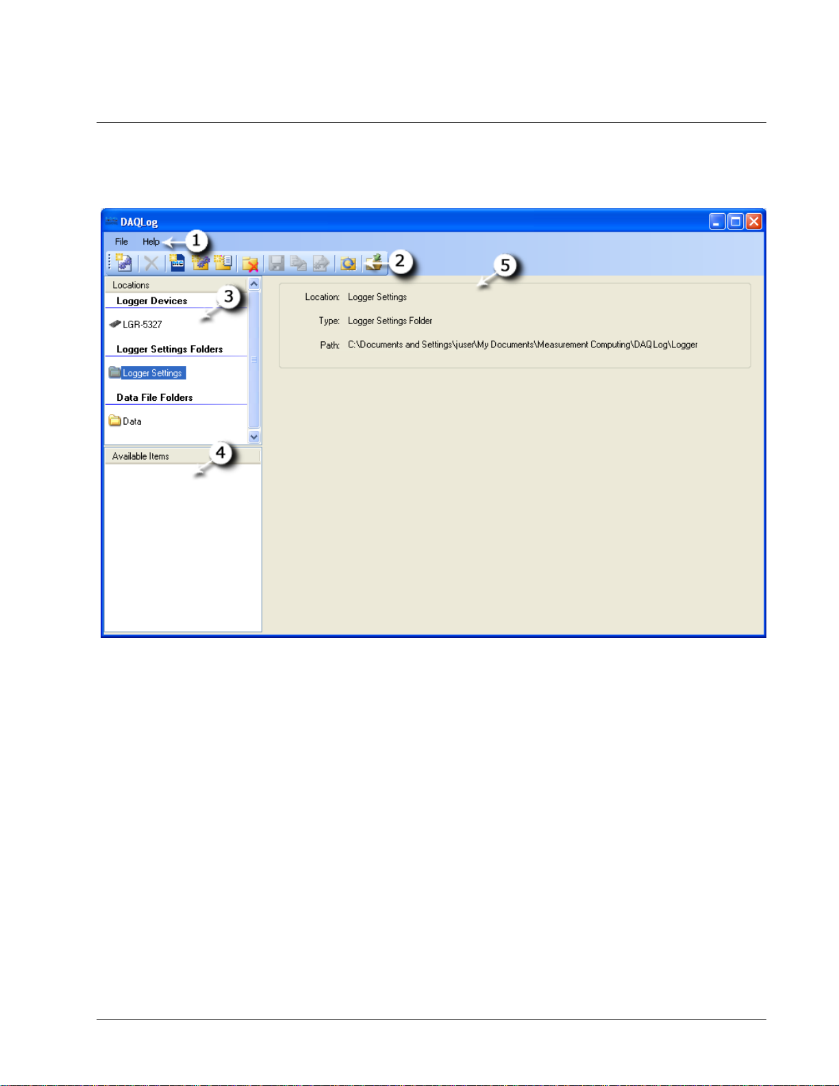
When you first run DAQLog with a LGR-5320 Series device connected to your computer, the main DAQLog
window lists the areas shown below.
Chapter 3
Figure 1. External DAQLog main window
Menu bar
Toolbar
Locations pane (divided into Logger Devices, SD Drives (when an SD card is connected), Logger Settings
Folders, and Data Folders sections).
Available Items pane
Displays information on the selected device, SD drive, folder, or file. When you select a configuration settings files in the
Available Items pane, a Log Setup, Channels, Acquisition, and Events tabs. These tabs appear when a settings file is
selected pane
DAQLog menu bar
The File menu contains options that:
Save a logger settings file
Deploy a logger settings file to an SD card or connected device
Locate the file selected in the
Convert a binary data file of logged data to a comma-separated format
Help menu contains options to open the DAQLog help file and to open an About DAQLog dialog that displays
The
software version information.
Available Items pane
10
Page 11
DAQLog Software User's Guide About the DAQLog user interface
See “Removing a data folder location” on page 34.
DAQLog Toolbar
The toolbar contains options for working with connected LGR-5320 Series devices, SD drives, settings files (.set)
and folders, data files (.dat) and folders, and converted data files (.csv).
New
Settings
File
Delete
Add SD
Drive
Add
Settings
Folder
Add Data
Folder
Remove
Location
Save
Launches a series of dialogs used to create a new configuration that is saved to the
selected destination (device, memory card, or settings folder). This file contains the
data acquisition parameters.
For more information, see “Creating a settings file” on page 17
.
Deletes the selected file in the Available Items pane.
See “Deleting settings files” on page 32
See “Deleting data files” on page 38.
.
Opens a dialog used to add an SD drive to DAQLog.
See
“Adding an SD ” on page 14.
Opens a dialog used to add folders for storing settings files.
See “Adding a se ttings folder location” on page 16.
Opens a dialog used to add folders for storing converted data files or folders containing
binary data files.
See “Adding a data folder location” on page 33 for more information.
Removes the selected settings folder, data folder, or SD drive from DAQLog Locations
without affecting the folder its e lf.
See “Removing a device from the DAQLog configuration” on page 13
See “Removing an SD drive” on page 15.
See “Removing a settings fold e r location” on page 17.
Saves the co nfiguration settings made to the selected location.
See “Modifying a settings file ” on page 27.
Convert
Data File
Converts the selected .dat file(s) to .csv files and stores them in the folder specified by
Output Location.
See “Converting data files” on page 35.
Deploy
Settings
File
Refresh
Location
Locate File
on Drive
Copies a settings file to a connected logger device, or, if no device is connected, to the
SD drive specified in the SD Drives pane.
See “Deploying a settings file to a LGR-5320 Series device" on page 30.
Updates the contents of a data folder after the contents of the folder have changed
(files are added to or removed from the DAQLog directory).
Opens Windows Explorer to the directory path of a selected folder or file.
See “Locating a settings file” on page 32
.
11
Page 12
Chapter 4
Working with Devices
DAQLog automatically detects all LGR-5320 devices that are installed and connected to your computer’s USB port.
Devices are detected when you first run DAQLog, and also if you install a device while DAQLog is running.
Devices are listed in the
Logger Devices area of the Locations pane.
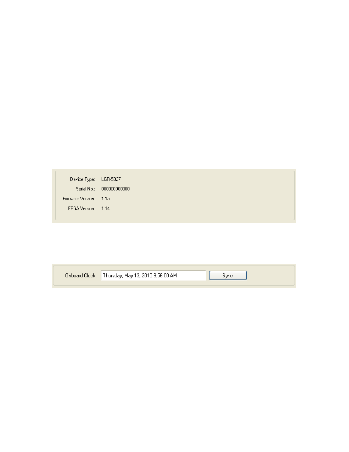
Viewing logger device inform a t ion
When you select a logger device and select Device Info in the Available Items location, the following information
about the device appears in the DAQLog window:
LGR-5320 Series device type
serial number
firmware version
FPGA ver s io n
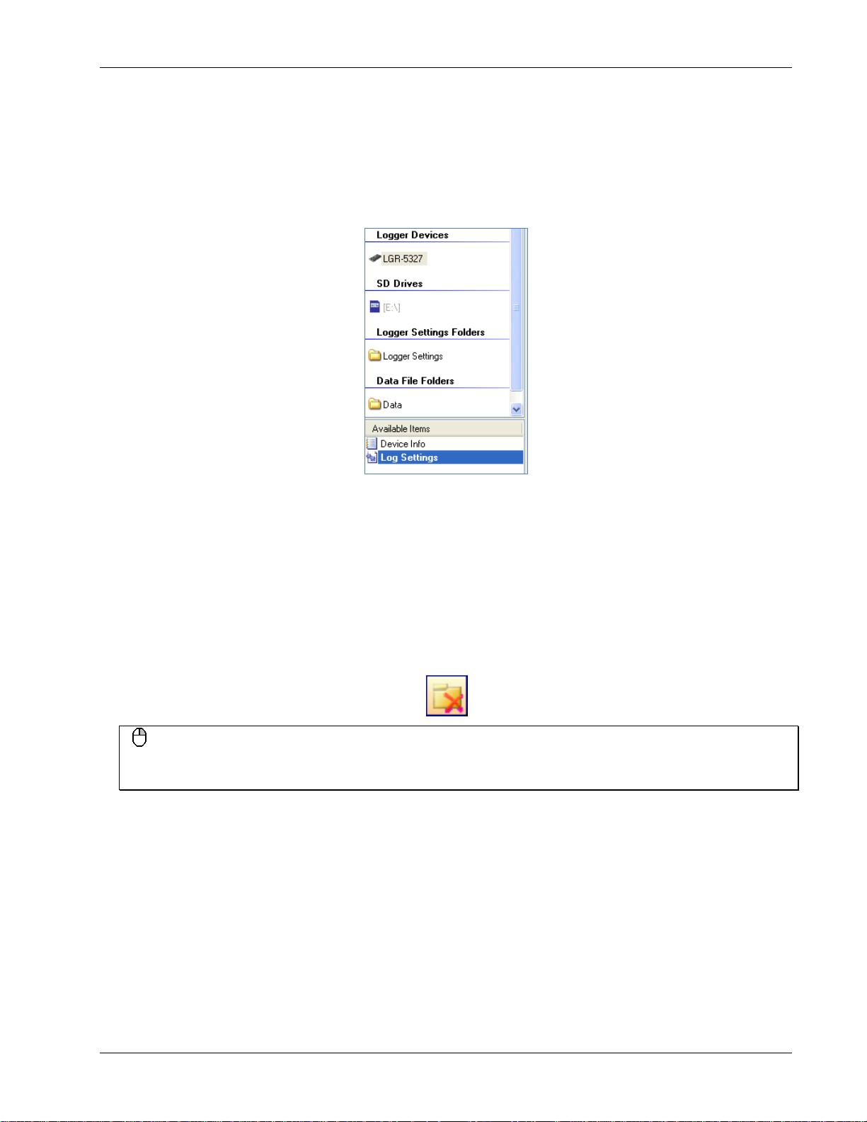
Synchronizing a device’s onboard clock
The Onboard Clock field lists the current time set on the device's internal clock.
To synchronize the clock of a LGR-5320 Series device with your computer’s clock, click
Sync.
The onboard clock does not change for daylight savings time. It keeps real time relative to the time synchronized.
12
Page 13
DAQLog Software User's Guide Working with Devices
Modifying a device’s c onfi guration settings
To modify the settings currently loaded on a LGR-5320 Series device:
1. Make sure the device is connected to a USB port on your computer.
1. Click on the d evice in the
2. Click on the Log Settings file in the
Logger Devices location.
Available Items pane.
Change the settings loaded on the LG R-5320 Series device from the Log Setup, Channels, Acquisition, and
Events tabs.
See “Modifying Log Setup parameters” on page 28 to learn how to modify settings using these tabs.
Removing a device from the DAQLog configuration
You can remove a device from the DAQLog configuration and the Logger Devices area in order to simplify the
number of deployment targets.
To remove a device from the DAQLog configuration, select it in the
Location icon from the DAQLog toolbar.
Right-mouse click method
You can also remove a device by right-clicking on it in the Logger Devices area and selecting Remove from t he
popup menu.
The device is removed from the Logger Devices area.
Logger Devices area and click the Remove
13
Page 14
Chapter 5
Working with SD Drives
You can store and deploy LGR-5320 Series device settings files to SD c a r ds installed on your computer or in the
device’s SD card slot. LGR-5320 Series devices also log data and events to files on an SD inserted in the device.
When you run DAQLog, you may need to manually add and remove SD cards from the DAQLog configuration.
Adding an SD drive
To manually add an SD drive to the SD Drives pane o n the main DAQLog window:
Add a volume name to your removable media
To differentiate between multiple SD cards and other removable media, use Windows Explorer to add a volume
name to each removable drive.
1. Click the Add SD Drive icon from the DAQLog toolbar.
Right-mouse click method
You can also add an SD drive by right-clicking anywhere in the Locations pane and selecting the Add…»SD Drive
option.
2. On the SD Drives pane, click on the SD card, and then click the Refresh Location toolbar icon.
The
SD Drive Selection dialog opens.
3. Click Continue».
The No New Storage Devices dialog opens if no SD card is detected. Connect an SD drive to the computer,
OK, and click Continue» again.
click
If an SD card is detected in a card reader or in a connected LGR-5320 Series device, another SD Drive
Selection dialog lists the available SD cards
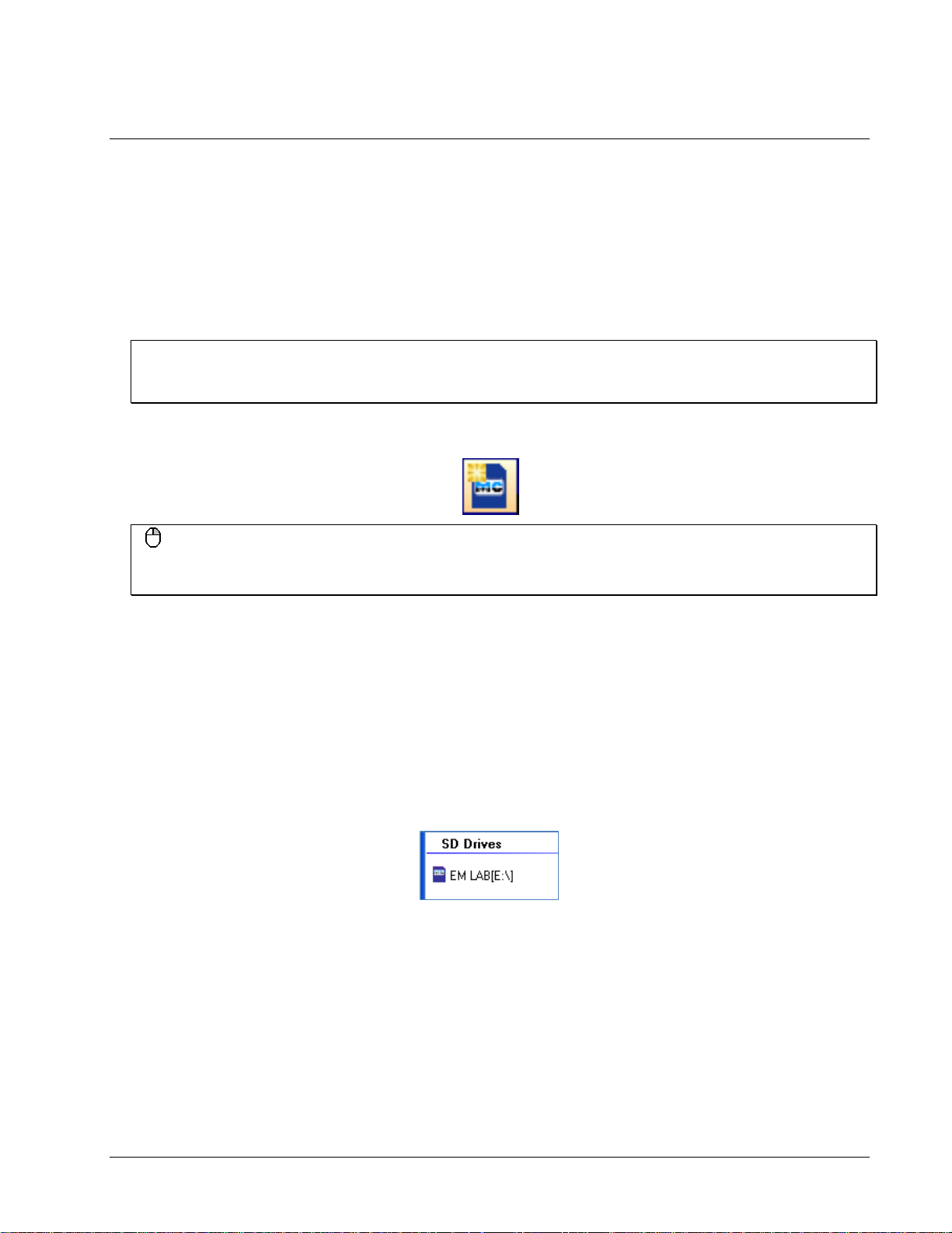
4. Select the drive letter of the SD drive you want to add, and click
The SD drive is added to the SD Drives pane as a drive letter and volume name.
Once you add an SD drive to DAQLog, you can perform the following operations:
OK.
14
Page 15

DAQLog Software User's Guide Working with SD Drives
Removing an SD drive
You may want to remove an SD drive from the DAQLog configur ation for the following reasons:
You do not plan to use the SD drive for data logging
The SD drive is no longer installed on your computer
You accidentally added removable media that is not an SD card
To remove an SD drive from the DAQLog configuration, select it in the
Location icon from the DAQLog toolbar.
SD Drives area, and click the Remove
Right-mouse click method
You can also remove an SD drive by right-clicking on it in SD Drives pane and selecting Remove from the popup
menu.
The SD drive is removed from the SD Drives area.
To add an SD drive back to the
SD Drives pane, refer to “Adding an SD ” on page 14.
Disconnected SD drives that have not been removed
If you disconnect an SD card from the comput er without u s ing the Remove Location icon or menu option, the SD
drive loca tion is grayed out on the DAQLog window until you connect the S D drive again.
15
Page 16

Chapter 6
Working with Settings Files and Folder Locations
You can configure a LGR-5320 Series device using settings (.set) files created with DAQLog.
A settings file contains parameter settings that determine:
the type of data the device logs (analog, digital, counter, event)
the source(s) of data (channels, ports), along with how those sources are configured (single-ended, differential)
how much data to log, and when a logging operation starts and stops (triggers, sampling rate, number of
samples)
the management of data files (folder structure, file naming conventions, and so on)
Settings files can be stored and deployed from your computer or from an SD card. You can create locations whose
main purpose is to store these types of files.
Adding a settings folder location
To add a new or existing folder loca tion to store settings files (.set), do the following:
1. Click the
Right-mouse click method
You can also add a settings folder location by right-clicking anywhere in the Locations pane and selecting the
Add…»Settings Folder option.
A Browse for Folder dialog opens.
2. To use an exis ting folder, navigate to the folder and select it.
To create a new folder, click
The new folder is created on your computer in the specified location.
The folder appears in the
settings files, those files are listed under
Once you create a logger settings folder location, you can:
Create a settings file to store in that folde r (see “Creating a settings file” on page 17)
Remove the folder from the DAQLog configuration (see “Removing a settings folder location” on page 17).
Add Settings Folder icon from the DAQLog toolbar.
Make New Folder, enter a name for the folder, and click OK.
Logger Settings Folders area of the Locations pane. If you add a folder that contains
Available Items.
16
Page 17

DAQLog Software User's Guide Working with Settings Files and Folder Locations
Removing a settings folder location
To remove a settings folder location from the DAQLog configuration, select the location you want to remove and
click the
You can also remove a settings location b y righ t-clicki ng the settin gs location and selecting Remove from the popup
menu.
The location i s removed from the Logger Settings Folder area, but remains on your comput er.
Removing a location from DAQLog does not delete the location from the computer. To add the location to the
DAQLog configuratio n again, refer to “Adding a settings folder location” on page 16
Remove Location toolbar icon.
Right-mouse click method
Creating a settings file
To create a settings file, select the location where you want to save the settings file from the Logger Settings
area, and click the New Settings File icon from the DAQLog toolbar.
Folder
Need to create a settings location?
If you do not see the Logger Settings Folder area in the Locations pane, you need to create a logger settings
location. Follow the instructio ns for “Adding a settings folder location” on page 16.
A series of New Log Settings…dialogs prompt you to configure your parameter settings.
Configuring the logging session
The New Log Settings…Configuring Logging Session… dialog contains parameters that determine:
the LGR-5320 Series device to configure
when logging occurs
how data files are saved,
what additional information is include d in data files (
relay behavior during logging
Name, Notes)
17
Page 18

DAQLog Software User's Guide Working with Settings Files and Folder Locations
Settings Target: Select the LGR-5320 Series device to configure with the settings file. By selecting a device,
DAQLog only shows settings that are c ompatible with that device.
If you select a settings target of LGR-5329 and try configure a LGR-5325 with that file, the LGR-5325 may not
support some of the settings, and the
SD STAT LED flas h es to indicate an error.
Name (optional): Enter a brief explanation of the configuration in the .set file. The name displays in the
Available Items list, with the actual file name in parentheses.
For example , if you enter LGR-5327 AI0 CI0 in the
5327 AI0 CI0(log_cfg.set)
Logging Options: Select any of these options that determine when logging begins, how data is stored, and
.
Name field, it appears in the Available Items list as LGR-
whether to operate the relay during logging.
Overwrite oldest log when memory full: The device overwrites the oldest log files when the SD card's
o
memory is full. If not sel ected, logging stops when the SD card's memor y is full.
Create hourly folders for new logs: The device creates a new subdirectory every hour to store logged
o
data.
Autostart new log on completion of current log: A new log session automatically begins after a log
o
session ends. Data from each log session is stored in a separate folder.
If not selected, you must start a new log session by pressing the device's
Autostart new log upon device powerup: The device immediately begins logging when powered on.
o
Otherwise, you must start logging by pressing the device's
Set relay when logging post-trigger data: The relay energizes at the start of post-trigger data, and
o
LOG button.
LOG button.
remains energized until the log sess i on ends.
Leave this option unchecked to eliminate the relay "click", and to reduce wear on the relay.
Set the parameters on this dialog and click
dialog.
Next>> to open the New Log Settings…Configuring Analog Inputs…
18
Page 19

DAQLog Software User's Guide Working with Settings Files and Folder Locations
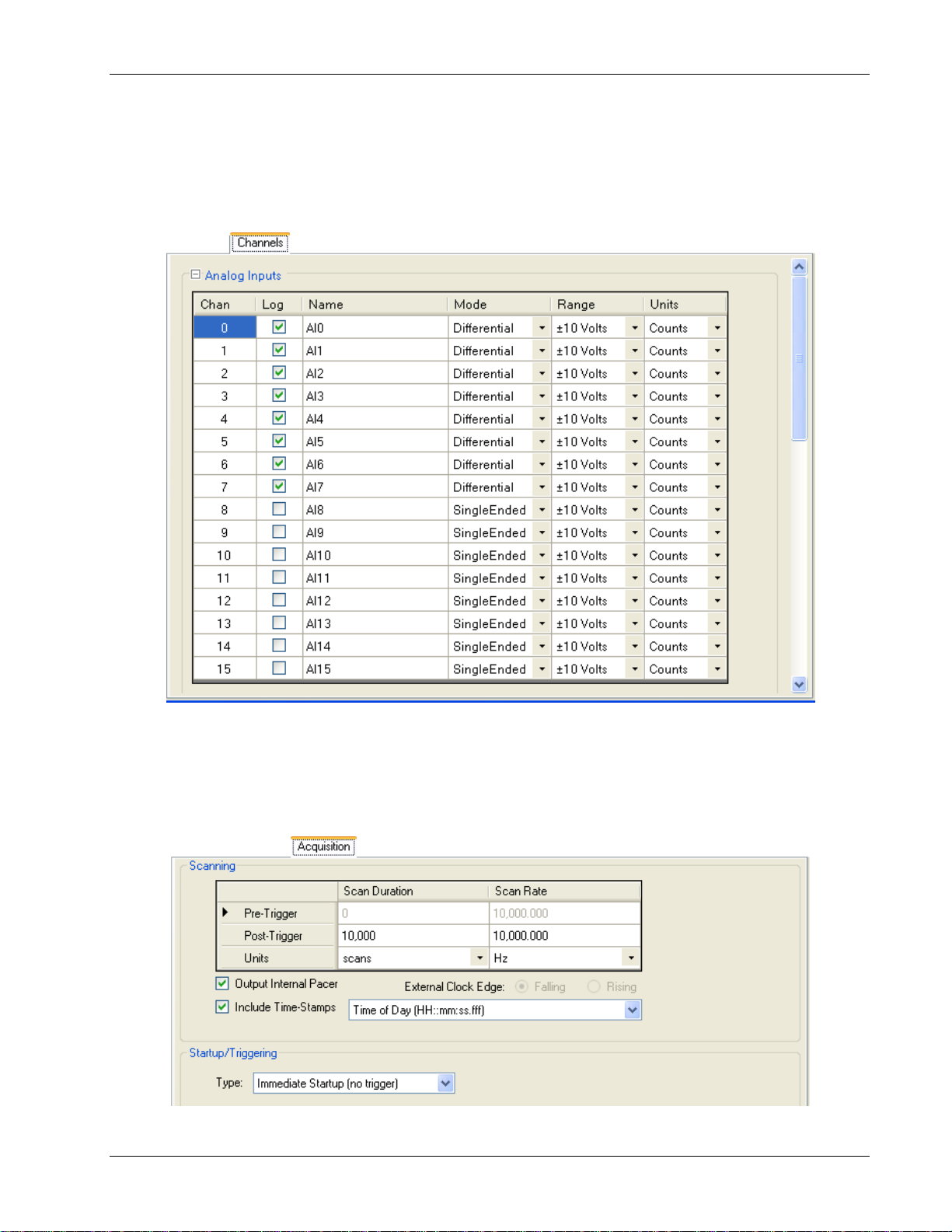
Configuring analog input parameters
The New Log Settings…Configuring Analog Inputs… dialog contains a grid of parameters that determine:
the analog input channels to log
the configuration mode of each analog input channel (single-ended or differential)
the voltage range of data to log
the units to use on the logged data
Each column in this grid is explained below.
Chan: List the number of each analog input channel. You cannot edit the numbers in this column.
Log: Select the check bo x of each analog channel whose data you want to log.
Name: Double-click on a cell in this column if you want change/add to the default name. This name appears in
the column he ader for the channel's l og data whe n you vi e w the data file in a spreadsheet.
Mode: Select the mode that the channel is physically wired to use whe n acquiring data.
Refer to the “Screw terminal pin out” section in the “Specifications” chapter of your LGR-5320 Series device
user’s guide for your device’s differential and sin gle-ended pin out.
Range: Select the voltage range of the data to log.
If you select ±30 Volts for a channel configured for differential mode, the associated high/low channel is also
set to ±30 Volts.
For example, if analog input channel 0 (
Range column, AI8 is also set to ±30 Volts.
Units: Select the units—Counts, Volts, or mV—to use when converting log data.
Set the analog input parameters on this dialog and click
Counter Inputs…
dialog..
AI0) is set to Differential in the Mode column and to ±30 Volts in the
Next>> to open the New Log Settings…Configuring
19
Page 20

DAQLog Software User's Guide Working with Settings Files and Folder Locations
Configuring counter input parameters
The New Log Settings…Configuring Counter Inputs… dialog contains three grids of counter parameters that
determine:
the counter input channels to log
the counter mode used for each counter input channel
the counter options available based on the counter
the reset, index, and modulo parameters
the default format of counter data when converted
the debounce filtering options to use on the logged counter data
Mode selection
Setting the counter mode and counter op tions
The parameters in the top grid of the
Counter Settings area are explained below.
Log: Select the check box of each counter channel whose data you want to log.
Name: Double-click on a cell in this column if you want change/add to the default name. This name appears in
the column header for the channel's log data when you view the data file in a spreadsheet.
Mode: Select the counter mode to use when logging data.
20
Page 21

DAQLog Software User's Guide Working with Settings Files and Folder Locations
o Counter: Use this mode for high-speed pulse and general counter operations. You can use the Index input
to clear, gate, latch, or decrement the counter.
Up/Down Counter: In this mode, phase A is the pulse source and phase B is the direction. The counter
o
changes direction depending on the state of phase B. The Phase B Edge setting determines whether a high
or low signal at phase B causes the counter to count up.
Encoder: Measure the system position (counts), velocity (counts per second), and direction of rotation.
o
This mode supports encoders with X1, X2, and X4 count modes.
Period: Measure the period of a signal at a counter channel's phase A input. You can measure x1, x10,
o
x100 or x1000 periods.
PulseWidth: Measure either the time from the rising edge to the falling edge, or the time from the falling
o
edge to the r ising edge o n a counter channel's pha se A input.
Timing: Measure the time between the rising or falling edge on the phase A input and the rising or falling
o
edge of the Index channel. The edges used are determined by the Phase A Edge and Index Edge options
settings.
Refer to the “Screw terminal pin out” section in the “Specifications” chapter of your LGR-5320 Series device
user’s guide for your de vi ce’s counte r signal pin out.
Option: Depending on the Mode selected, you can set these counter options:
Counter and Up/Down Counter mode options
TotalizeThe counter c ounts rising edges or fa lling edges.
o
Clear On Read: The counter is cleared after each synchronous read. The counter value is latched and
o
returned before it clears.
Encoder mode options
1X: Counts rising or falling edges on phase A, depending on the phase A Edge setting (Encoder mode
o
only).
2X: Counts rising edges and falling ed ges on phase A.
o
4X: Counts rising edges and falling ed ges on phase A and phase B.
o
Period mode options
1 Period: The measurement latches after one complete period is observed
o
10 Period:The measurement latches after 10 complete periods are observed .
o
100 Period:The measurement latches after 100 complete periods are observed.
o
1000 Period:The measurement latches after 1000 complete periods are observed.
o
Tick Size: For Period, PulseWidth and Timing modes, you can set the counter tick size measurements. The
system clock of the field programmable gate array (FPGA) is 20 ns.
20 ns: Sets the counter channel's tick size (timebase) to 20 nanoseconds.
o
200 ns: Sets the counter channel's tick size to 200 ns.
o
2 µs :Sets the counter channel's tick size to 2 microseconds
o
20 µs: Sets the counter channel's tick size to 20 µs
o
Setting reset, index, and modulo parameters
The parameters in the bottom grid of the
Counter Settings area of the dialog are explained below.
21
Page 22

DAQLog Software User's Guide Working with Settings Files and Folder Locations
No Reset: Select this check box to have the counter continue counting without resetting before each scan
operation.
Index: Depending on the Mode selected, you can set the function of the counter index from the following
options:
No-Op: Ignore the Index signal.
o
Clear: When Encoder mode is selected, the Index signal clears the counter when counting up, or reloads
o
the modulo number counting down (see Modulo N below).
Gate: For all counter modes except Timing, the Index signal gates the counter. By default, the counter is
o
enabled whe n the Index signal is hi gh. When the Index signal is low, the counter is disabled, but holds the
count value.
You can change gate pola rity using the
Decrement: When Counter mode is selected, the Index signal decrements the counter.
o
Latch: When Counter or Encoder mode is selected, the Index signal latches the counter.
o
Index Edge: Select the edge or polarity on the Index input.
Modulo N: Enter upper limit of the count. The modulo number can range from 1 to 4,294,967,295
Index Edge parameter.
(0xFFFFFFFF), which is the maximum 32-bit counter value. The default is 4294967296 (0xFFFFFFFF).
When counting up, the co unter rol ls over to 0 when Modulo N is reached, and then continues counting up.
When counting down, the counter rolls over to Modulo N whenever the co unt reaches 0, and then continues
counting down.
Format option setting determines whether this number is displayed as a decimal or hexadecimal.
The
Modulo Mode: Select how the counter behaves when the counter reaches the Modulo N number:
Rollover: The counter rolls over to a count of 0 and continues counting.
o
RangeLimit: When counting up, the counter counts up to Modulo N and stops. Counting resumes if the
direction reverses or the counter is cleared.
When counting down, the counter counts down to 0 and stops. Counting resumes if the direction reverses or
the counter is cleared.
NoRecycle: The counter is disabled if a count overflow or underflow occurs. The counter is re-enabled
o
when a reset or load operation is performed.
Format: Select whether converted counter data is displayed in decimal or hexadecimal numbers. The Modulo N
number also displays in this format.
You can select the format before you convert the data.
Setting debounce filter parameters
The parameters in the
Counter Input Settings grid on the dialog are explained below.
Debounce: Select the check box of each channel that you want to apply the debounce settings.
Debounce Mode: Select one of these debounce mode options:
AfterStable: Rejects glitches and only changes state after a specified period of stability (set with the
o
Debounce Time parameter).
Use this mode with electro-mechanical devices like encoders and mechanical switches to reject switch
bounce and disturbance s due to a vibrating encoder that is not otherwise moving. Set the debounce time
short enough to accept the input pulse you want, but longer than the period of the disturbance.
22
Page 23

DAQLog Software User's Guide Working with Settings Files and Folder Locations
o BeforeStable: Immediately changes state, and does not change state again until a specified period of
stability (
Debounce Time) passes.
Use this mode when the i nput signal has groups of glitches, and you want each group to be counted as one.
This mode r ecognizes and count the fi rst glitch within a group, but rejects the subsequent glitches within
the group if the debounce time is set accordingly. Set the debounce time to encompass one entire group of
glitches.
Debounce Time: Select from 16 programmable debounce times in the range of 0.5 µs (500 ns) to 25.5 ms.
Phase A Edge: Select the edge or polarity on the Phase A input.
Phase B Edge: Select the edge or polarity on the Phase B input.
Phase A, Index inputs on devices that do n o t support encoders
LGR-5320 Series devices that do not support encoder counting, connect the phase A input to the CTRx screw
terminal, and the Index input to the Gatex screw terminal.
Set the counter input parameters on this dialog and click Next>> to ope n the New Log Settings…Configuring
Digital Inputs… dialog.
Configuring digital input parameters
The New Log Settings…Configuring Digital Inputs… dialog contains one grid of digital input parameters that
determine:
the digital port to log
the format of digital data when conver te d
These parameters are explained below.
Log: Select the check box to log data from all connected digital inputs.
Name: Double-click in the Name colu mn to change the name of the digital port.. This name appears in the
column header for the channel's log data.
Format: Select the number format used for converted digital data.
You can select the format before you convert the data.
Decimal: Data is converted to a decimal number.
o
Hexadecimal: Data is converted to a hexadecimal number.
o
Binary: Data is converted to a binary value.
o
Bitwise: Data is converted to a binary data, with each bit separated by a comma.
o
Configure the digital i nput parameters on thi s dialog and cl ick
Acquisition Startup, Timing and Duration… dialog.
Next>> to open the New Log Settings…Configuring
Configuring startup, timing, and duration parameters
The New Log Settings… Configuring Acquisition Startup, Timing and Duration … dialog contains parameters
that determine:
the number of samples to acquire before and after a scan is triggered,
the sample rate before and after a scan is triggered.
the units used to measure the scan duration and scan rate
whether the onboard clock is available at the PACER terminal
the type of trigger used to start a logging session
23
Page 24

DAQLog Software User's Guide Working with Settings Files and Folder Locations
These parameters are explained below.
Pre-Trigger : For all Startup/ Triggering Type selections except Immediate Startup (no trigger), you can
configure these pre-trigger parameters:
Scan Duration: The number of samples or length of time to acquire before the trigger.
o
Scan Rate: The sample rate per channel used to acquire pre-trigger data.
o
Changes to
ExtClock Divisor: Disabled. Set this parameter in the Post-Trigger row when Units is set to External.
o
Post-Trigger: You can configure these post-trigger parameters:
Scan Duration: The number of samples or length of time to acquire after the trigger.
o
Scan Rate: The sample rate per channel used to acquire post-trigger data.
o
Changes to
ExtClock Divisor: Available when Units is set to External. The number used to divide the external clock
o
ExtClock Divisor when Units is set to External.
ExtClock Divisor when Units is set to External.
rate. The default setting of 1 paces the acquisition at the same rate as the external clock frequency.
Units: Sets the units to use for Scan Durat ion and Scan Rate. Also configures the device for an external clock
source.
Scan Duration: Sets the units used to measure the length of the acquisi tion.
o
scans: The number of samples to acquire.
msec: The length of time in milliseconds to acquire samples.
s: The length of time in seconds to acquire samples.
min: The length of time in minutes to acquire sa mples.
hr: The length o f t ime in hours to acquire samples.
Scan Rate: Sets the units used to measure the sample rate, or instructs the device to use an external clock
o
source to determine the acquisition rate.
External: Determine the sample rate from an external clock. Connect the device’s
PACER screw terminal
to an external clock, such as the pacer output of another logger device.
When selected, the
changes to
ExtClock Divisor .
External Clock Edge radio buttons are enabled, and the Scan Timing column header
Hz: Hertz
MHz: Megahertz
kHz: Kilohertz
s: Second
24
Page 25

DAQLog Software User's Guide Working with Settings Files and Folder Locations
Output Internal Pacer: Select this check box to make the onboard clock available at the PACER terminal (to
use the device as the clock source for another device, for example).
External Clock Edge: Set the trigger edge of the external clock to either Rising or Falling.
This optio n is only enable d when
Include Time-Stamps: Set the default timestamp format include d with logged data. Select from the following
Units is set to External.
options:
o None: No timestamp included with logged data.
o Seconds from Start (ss:ffffff): Record the number of seconds that the data was logged after data acquisition
began. Time displays as "seconds::fractions of a second (floating point)". For example, 0.0006.
o Time of Day (HH::mm::ss::fff):Record the time of day that t he d a ta was logged. Time displays as
"hours::minutes::seconds::fractions of a second (floating point)". For example, 10:08:19.035.
o Date and Time-US (MM/dd/yyyy HH:mm:ss:fff):Record the date and time that the data was logged.
Date/time displays as "month/ day/year hours::minutes::seco nd s::fractions of a second (floating po int)". For
example, 04/05/2010 10:08:19.143.
o Date and Time (yyyy-MM-dd HH:mm:ss:fff):Record the date and time that the data was logged. Date/time
displays as "month/day/year hours::minutes::seconds::fractions of a second (floating point)". For example,
2010-04-05 10:08:19.984.
Startup/ Triggering: Select the type of trigger that starts the acquisition from the Type listbox:
Immediate Startup (no trigger): The acquisition begins when you press the device’s START button.
o
Autostart new log upon device powerup checkbox is selected (see on page 18), logging starts
If the
immediately if the device is powered and not connected to a computer’s USB port.
Digital Trigger: The acquisition begins when the conditions of a digital trigger ar e met. You set these
o
conditions with these parameters.
Edge: Set the edge on which to trigger as Rising or Falling. (edge trigger) or as High or Low (level trigger)
Edge (vs Level) Sensitive: Select this checkbox to set the trigger to edge sensitive.
Clear this checkbox to set the trigger to level sensitive.
Analog Trigger: The acquisition begins when the conditions of an analog trigger are met. You set these
o
conditions with these parameters:
Edge/Level: Select whether the trigger is Edge Sensitive (triggers on a rising or falling edge), or Level
Sensitive (triggers when the signal is above or below a threshold value. Set this p arameter in conjunction
with the
Polarity: Select Rising/Above Threshold to trigger when the signal rises above the threshold value, or
Falling/Below Threshold to trigger when the signal drops be low a threshol d value.
Threshold/Hysteresis: Enter the threshold and hysteresis values. Threshold is the voltage level of the
trigger point. Hysteresis is the
Range: Select +/- 10 Volts when you are using a l ow voltag e trigger sig nal (10 V) connected to the logger
Polarity parameter.
Range that a signal must pass through before that signal can cause a trigger.
device's analog trigger input pin.
Select +/- 30 Volts when you are using a high voltage trigge r signal (30 V) connected to the device's analog
trigger inp ut pin.
Multi-Channel Trigger: The acquisition begins when the c ondition s of a multi-channel trigger are met. You
o
set these condition with these parameters.
Logic: Select And/All to trigger the acquisition when the conditions for all channels are true.
Select Or/Any to trigger the acquisition when one or more channel conditions are true.
Configure the trigger c onditions for each channel using the parameters in the multi-channel grid.
Apply: Select this check box to configure the channel wi th the selected trigger options.
Type: Select the type of t rigger to use on the selec ted channe l . Only the trigger types supported by the
connected device are listed.
AboveThreshold: Triggers a logging session when the signal l evel rises above the thre shold. T he trigger
stays valid until the signal level drops below the hysteresis range.
25
Page 26

DAQLog Software User's Guide Working with Settings Files and Folder Locations
BelowThreshold: Triggers a logging session when the signal level drops below the threshold. The trigger
stays valid until the si gnal level r i s es above the hysteresis range.
AboveThresholdWithLatch: Triggers a loggi ng session when the signal level ri ses above the threshold. The
trigger stays valid unt i l the acquisition is complete and re-armed.
BelowThresholdWithLatch: Triggers a loggi ng session when the signal level drops below the threshold . The
trigger stays valid until the acquisition is complete and re-armed.
RisingEdge: Triggers a loggin g s ession when the signal level drops below the hysteresis range and then
rises above the thresho l d. The trigger stays valid until the signal level drops bel ow the hysteresis range
again.
FallingEdge: Triggers a logging session when the signal level rises above the hysteresis range and the n
drops be low the thresho l d. The trigger stays valid until the signal leve l rises above the hysteresis range
again.
RisingEdgeWithLatch: Triggers a logging session when the signal level drops below the hysteresis range
and then rises above the threshold. The trigger stays valid u ntil the acquisition is complete, re gar dless of the
signal level.
FallingEdgeWithLatch: Triggers a logging session when the signal level rises above the hysteresis range
and then dr ops below the t hreshold. The trigger stays valid until the acquisition is c omplete, regardless of
the signal level.
Digital Pattern (Mis)Match Trigger: The loggi ng ses s io n b egins when the conditions of a digital pattern
o
trigger are met. You set these conditions with these parameters.
Condition: Select Equal to Pattern (==) to trigger the l og gi ng se ss io n when the binary numbers on a
digital connector exactly matches a defined bit pattern. To trigger the logging sessi on when the p atterns
don't match, select
Pattern: Click on each bit (0 to 15 ) to set its value and define the bit pattern. Click once to set the bit to 0.
Differ from Pattern (<>).
Click again to set the bit to 1. Leave set to "X" (don't care) to exclude that bit from the comparison.
Click the
All button to cycle through setting al l bits simultaneously to 0, 1, or X.
Configure these startup, timing, a nd duration, parameters on this dialog , and click
Settings…Configuring Event Recording… dialog.
Next>> to open the New Log
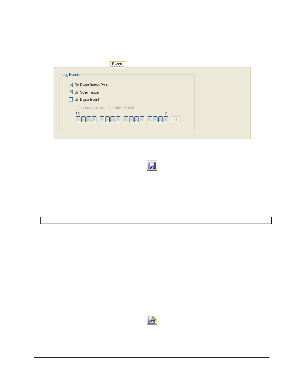
Configuring event log parameters
The New Log Settings… Configuring Event recording … dialog contains parameters that deter mine the events to
log during a lo gging session.
If you select any of the checkboxes on this screen, a separate event (.evt) log file is created along with the data file
(.dat) during a logging session.
These parameters are explained below.
On Event Button Press: Logs an event each time you press the device's EVENT button.
On Scan Trigger: Logs an event each time a logging session is triggered.
26
Page 27

DAQLog Software User's Guide Working with Settings Files and Folder Locations
On Digital Event: Logs one of the following digital events:
State Change: Logs an event anytime the digital inputs change state.
o
Pattern Match: Logs an event each time the digital inputs match the defined pattern. A"1" indicates an
o
active digital input, "0" indica te s an inactive bit, and "X" denotes bits to ignore.
Configure these event parameters on this dialog , and click
The settings file is saved and listed in t he
Available Items pane on the main DAQLog windo w.
Finish .
Modifying a settings file
You may want to change some parameters in a settings file after you create it. You can change any parameter in a
settings file except for the target device. You should create a new settings file if you want to configure another type
of LGR-5320 Series device.
The initial step you take depends o n where the settings file you want to modif y is located.
Modifying settings stored on an SD card
To modify a settings file stored on an SD card:
1. Click on the SD card in the
2. Browse the files and folders in the
SD Drives location.
Available Items pane, and select the .set file you want to modify.
Change the settings in t he file from the Log Setup, Channels, Acquisition, and Events tabs.
See “Modifying Log Setup parameters” on page 28 to learn how to modify settings using these tabs.
Modifying settings stored in a settings location
To modify a settings file stored in a settings location:
27
Page 28

DAQLog Software User's Guide Working with Settings Files and Folder Locations
1. Click on the settings file in the Logger Settings Folder area.
2. Browse the files and folders in the
Available Items pane, and select the .set file you want to modify.
Change the settings in t he file from the Log Setup, Channels, Acquisition, and Events tabs.
See “Modifying Log Setup parameters” below to learn how to modify settings using these tabs.
Modifying Log Setup parameters
Click on the Log Setup tab to modif y the logging session parameters in the file.
See “Configuring the logging session” on page 17 for detailed explanation of these parameters. You can change all
settings except for the
Settings Target.
28
Page 29
DAQLog Software User's Guide Working with Settings Files and Folder Locations
Modifying Channels parameters
Clicking on the Channels tab to modify the parameters that determine the analog, counter, and digital input data to
log. Use the scroll bars to scroll the grid down to display the counter and digital input parameters.
See “Configuring analog input paramete rs” on page 19, “Configuri ng counter input parameters” on page 20, and
"Configuring digital input parameters” on page 23 for detailed explanation of these parameters
Modifying Acquisition parameters
Clicking on the Acquisition tab to modify parameters that determine the startup, timing, and duration of a logging
session.
See “Configuring startup, timing, and duration parameters” on page 23 for a detailed explanation of these
parameters.
29
Page 30
DAQLog Software User's Guide Working with Settings Files and Folder Locations
Modifying Events parameters
Click on the Events tab to modify parameters that determine the events to lo g.
See “Configuring event log p arameters” on page 26 for a detailed explanation of these parameters.
Saving your settings changes
When you are done modifying the parameter settings, click the Save toolbar icon.
The changes yo u made to the settings file are saved in the same location.
Deploying a settings file to a LGR-5320 Series device
Once you ha ve a settings file you want to use to configure a LGR-5320 Series device, you can deploy the file to an
SD card in a card reader installed on your computer. You can then remove the SD card from the reader, insert the
card in the card slot in logger device, and load the configuration onto the device.
Other methods to deploy and load a settings file
Deploying a settings file over a USB connection
If your LGR-5320 Series device is connected to your computer’s USB port, you can deploy and load a settings file
in one of the following ways:
Directly to the device’s memory.
To the SD card in the device’s card slot
Deploying directly to a LGR-5320 Series device
To copy, or deploy, your settings file from a settings folder location directly to your DAQLog, follow these steps.
1. Make sure the device is connected to a USB port on your computer.
2. Select the settings folder location where the settings file is stored.
3. Select the settings file in the
4. Click on the Deploy Settings File to olbar icon on the toolbar.
Available Items pane.
If you have multipl e de vices installed, a Select Settings Target dialog opens.
5. Select the device to deploy to, and click
Deploy.
30
Page 31
DAQLog Software User's Guide Working with Settings Files and Folder Locations
Click-and-drag method
You can also deploy a .set file to a device by clicking-and-draggi ng i t from the Available Items pane to the
Logger Devices location.
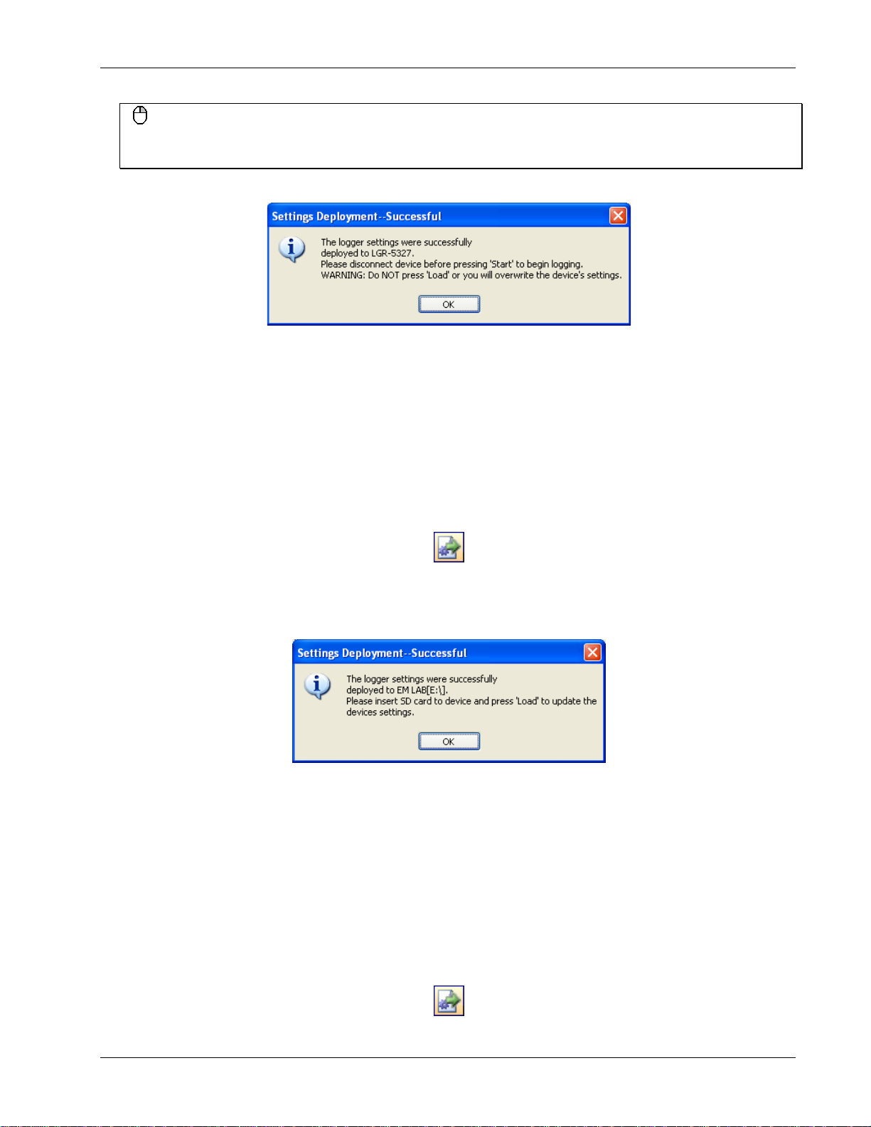
The Settings Deployment—Successful prompts you when the file deploys successfully.
The settings file is deployed and loaded to the LGR-5320 Series device’s memory. Your device is ready to log data
using the configuration in this settings file.
Deploying to the SD card in a DAQLog
To copy, or deploy, your settings file from a settings folder location on your computer t o the SD card in your LGR5320 Series device, follow these steps.
1. Make sure the device is connected to a USB port on your computer.
2. Select the settings folder location where the settings file is stored.
3. Select the settings file in the
Available Items pane.
4. Click on the Deploy Settings File to olbar icon.
If you have multiple SD cards and/or devices installed, a Select Settings Target dialog opens.
5. Select the SD card in your device, and click
The
Settings Deployment—Successful dialog prompts you when the file deploys successfully.
Deploy.
6. Disconnect the USB cable from the device if it is connected.
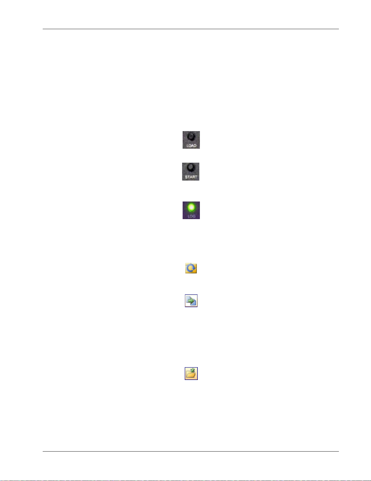
7. Press
LOAD on the device to load the settin gs file configuration to the device.
Your DAQLog is ready to log data using the configuration in this setti ng s file
Deploying a settings file to an SD card in a card reader
To copy, or deploy, your settings file from a settings folder location on your computer t o an SD card, follow these
steps.
1. Select the settings folder location where the settings file is stored.
2. Select the settings file in the
3. Click on the Deploy Settings File to olbar icon.
Available Items pane.
31
Page 32

DAQLog Software User's Guide Working with Settings Files and Folder Locations
If you have multipl e SD cards and/or devices installed, a Select Settings Target dialog opens.
4. Select the SD card to deploy to, and click
Click-and-drag method
You can also deploy a .set file to an SD drive by clicking -and-draggi ng it from the Available Items pane to the SD
Drives location.
The Settings Deployment—Successful dialog prompts you when the file deploys successfully.
5. Remove the SD card from the card reader, and insert it into the SD card slot on the device.
6. Disconnect the USB cable from the device if it is connected.
7. Press
Your DAQLog is ready to log data using the configuration in this setti ng s file
LOAD on the device to load the settin gs file configuration to the device.
Deploy.
Click-and-drag method
You can also deploy a .set file by clicking-and-d ragging it from a Available Ite m s pane to the SD Drives location
or Logger Devices location.
Locating a settings file
You can also use DAQLog to open a folder location containing a settings file in Wi ndows Explorer.
To open the location of a settings file in Windows Explorer, select the se ttings folder location or settings file and
click the Locate File on Drive toolbar icon.
Windows Explorer opens the settings folder location.
Deleting settings files
You can delete one or more settings files from a ny folder location in the DAQLog configuration.
To delete settings files from a settings folder location, follow these steps.
1. Select the settings folder location where the settings file is stored.
2. Select the settings file(s) in the
3. Click the Delete toolbar ico n.
Available Items pane. Use the Ctrl and Shift keys to select multiple files.
Keyboard method
You can also select the file(s) and click the keyboard's Del key to delete the file(s).
The file is removed from the Available Items pane and deleted from the location where it was stored.
32
Page 33

Chapter 7
Working with Data Folder Locations, Data Files, and Converted Data Files
LGR-5320 Series devices use data (.dat) and event (.evt) files to store the data and record events during a logger
session.
A data file is a binary file that contains data from a logging sessio n. Data files can be stored on your computer and
on an SD card.
You can also create locations whose main purpose is to store converted data files.
You can convert these binary data files to a comma separated value (csv) file that you can view in a spreadsheet
application.
An event file logs event s based on the c onfiguration of a logging session.
Adding a data folder location
To add a ne w or existing folder location to stor e data files (.dat), do the following:
1. Click the
Right-mouse click method
You can also add a data folder location by right-clicking anywhere in the Locations pane and selecting the
Add…»Data Folder option.
A Browse for Folder dialog opens.
2. To use an exis ting location, na vigate to the location and select it.
To create a new folder, click
The new folder is created on your computer in the specified location.
The location appears in the
and/or event files, those files are listed under
Once you create a logger data location, you can:
Create a settings file to store in that location (see “Creating a settings file” on pa ge 17)
Add Data Folder icon from the DAQLog toolbar.
Make New Folder, enter a name for the folder, and click OK.
Data File Folders area of the Locations pane. If you add a location that contains data
Available Items.
Remove the folder location from the DAQLog configuration (see “Removing a settings folder locatio n” on page
17)
33
Page 34

DAQLog Software User's Guide Working with Data Folder Locations, Data Files, and Converted Data Files
Removing a data folder location
To remove a data folder location from the DAQLog configuration, select the location you want to remove and click
Remove Location toolbar icon.
the
Right-mouse click method
You can also remove a data folder location by right-clicking t he settings location and selecting Remove from the
popup menu.
Thefolder location is remo ved from the Data Files Folder area, but remains on your computer.
Removing a data folder loca tion from DAQLog does not delete the location from the computer. To add the location
to the DAQLog configuration again, refer to “Adding a data folder location” on page 33.
Creating a data file
A LGR-5320 Series device creates a data file based on the device’s current logging sess io n configuration.
You configure when the device creates a data file from the
dialog when you create a settings file (see “Configuring the logging session: on page 17).
You can modify this setting from the
Log Setup tab when you select the settings file.
New Log Settings…Configuring Logging Session…
34
Page 35

DAQLog Software User's Guide Working with Data Folder Locations, Data Files, and Converted Data Files
Converting data files
In order to view and analyze DAQLog data and events, you must convert the data and event files to a comma
separated value (.csv) file, and then open the .csv file in a spreadsheet application.
Once you have logged data on a LGR-5320 Series device, you can convert the data and event files in one of the
following ways:
Directly from SD card in the device over a USB connection
From an SD card in card reader installed on your computer device’s card slot
Before you learn how to conv er t a data file to a .csv file, learn about the options included in DAQLog for storing
and organizing these converted file.
Setting converted data file storage parameters
DAQLog stores converted data files in locations that are named based on the date of the log file being converted.
Optionally, you can also have DAQLog create subfolders named for the device type and/or serial number of the
logging device.
To view and/or change data file storage parameters:
1. Select a folder location in the
The data file storage options display on the DAQLog window.
2. Set the
Store By: parameters.
o By default, DAQLog stores the .csv file in a folder named for the date the logging file was created.
o Select the
o Select the
Device Name check box to store data in subfolders by the device name, then date created.
Serial No. check box to store data in subfolders by the serial number, then date created.
Data File Folders area.
35
Page 36

DAQLog Software User's Guide Working with Data Folder Locations, Data Files, and Converted Data Files
o Select both check boxes to store data in subfolders by device name, serial number, then date created.
3. Set the
Date Directories parameter:
o Select the
Separate Date Fields radio button to store data in folders named for date the log was started.
The file is named using the date format YYYY-MM-DD.
o Select the
Split into Subdirectories radio button to store data in separate subfolders for the year, month,
and day that the data was acquired.
o Select the
Keep the Same radio button to store data in subfolders named for the da te the log was started.
Files are named using the date format YYYYMMDD.
o Keep The Same – select this radio button to store data under the date the log was started. the date is
formatted as YYYYMMDD; for example
4. Set the
Base Name parameters.
\20100426\.
36
Page 37

DAQLog Software User's Guide Working with Data Folder Locations, Data Files, and Converted Data Fi le s
o In the Data field, enter the characters added to the beginning of name of the converted data file.
By default, a data file named 00006.dat converts to log00006.csv.
o In the
Event field the characters add ed to the beginning of name of the converted data file. By default,
"evt" is appended to the file name. For example, entering
evt converts 00006.evt to evt00006.csv.
By default, an event file named 00006.evt converts t o evt00006.csv.
Converting a data file
To convert a data file, follow these steps.
1. Select the location where the data file is stored (usually one of the
The
Available Items pane lists folders named based on the date you performed the logging operation. The date
SD Drives locations).
format used is “YYYYMMDD.”
For example, the folder shown below was created on April 28, 2010.
2. From the Available Items pane, click on the folder location containing the data, and then select the file to
convert.
When you select a data file, you can change some of the parameters on the
Data Conversion and Settings tab
for converting the data file. Changing these p arameters only changes the parameters for the current
conversion—the stored defaults remain unchanged.
3. Click the
Refresh Location toolbar icon.
4. From the Location listbo x, select the folder location where you want the converted data to be stored.
5. Click on Settings tab to view the timestamp, pre-trigger and post-trigger, and channel configuration used when
logging data to the data file.
You can change the time stamp format, channel names, and units parameters used during the log ging sessio n.
See “Configuring startup, timing, and duration parameters” on page 23 to learn how to change the time stamp
format.
See “Configuring analog input paramete rs” on page 19 to learn how to change the channel names and units.
You change channels na mes using the same method for analog, counter, a nd digital channels.
6. Click on the
Convert Data File icon on the toolbar.
A progress bar shows the progress of the conversion operation.
The .csv file is saved in the folder location you selected from the
Location listbox.
37
Page 38

DAQLog Software User's Guide Working with Data Folder Locations, Data Files, and Converted Data Files
Viewing data and event files
Once you convert a DAQLog data file to a.csv file, you can view it in a spreadsheet application by following these
steps:
1. On the
2. Browse the folder in the
Data File Folders pane, click on the folder location conta i ning the .cs v file you want to view.
Available Items pane until you see t he .csv file, and then click the Locate File on Drive
toolbar icon.
3. The selected folder location opens in Windows® Explorer, with the selected file highlig hted.
4. Examples of a .csv data file and .csv event file opened in Microsoft® Excel® are shown below.
5. The scatter chart shown was added to the file, and is not generated during file conve rsion.
Converted data file (.csv) in spreadsheet.
Converted event file in spreadsheet.
Deleting data files
You can delete a data file from the DAQLog configuration and from the selected location (usually an SD card).
To delete one or more data files, follow these steps.
1. Select the SD card or other location where the data file(s) is stored.
2. Select the data file(s) in the
Use the
Ctrl and Shift keys to selec t multiple files.
Keyboard method
You can also select the file(s) and press the Del key to delete the file(s).
The file is removed from the Available Items pane and deleted from the location where it was stored.
Available Items pane, and click the Delete toolbar icon.
38
Page 39

Chapter 8
DAQLog Walkthrough: Logging Data with a LGR-5320 Series Device
This chapter provides a step-by-step walkthrough of how to configure a LGR-5320 Series device using DAQLog,
and then log data with the device using the configuration.
This example logs data from a single analog chan nel (AIO), a nd logs an event when the
device is pressed.
This chapter assumes you have already completed the steps in the “Getting Started” chapter on page 9.
TRIG/EVENT button on the
Create a new logger settings file
Follow these steps to create the settings file.
1. Click the
2. On the New Log Settings--Configuring Logging Session… dialog:
o Select LGR-5327 from the
o Enter AI0 SE in the
o Enter DAQLog walkthrough that logs one analog channel and records button press events in the
New Settings File icon from the DAQLog toolbar.
Settings Target listbox.
Name field.
field, and click
Next>>.
Notes
39
Page 40

DAQLog Software User's Guide DAQLog Walkthrough: Logging Data with a LGR-5320 Series Device
3. On the New Log Setting--Configuring Analog Inputs… dialog:
o Select the
o Select SingleEnded from the
o Select ±10V from the
o Select ±Volts from the
Log checkbox for AI0, and clear all other checkboxes.
Mode listbox.
Range listbox.
Units listbox, and click Next>>.
4. On the next t wo dialogs, accept the defaults by clicking Next>>.
Counter or digital channels are not logged in this example.
5. On the
New Log Settings--Configuring Acquisition Startup, Timing, and Duration… dialog:
o Set the
o Set the
Scan Duration to 200 (Post-Trigger row)
Scan Rate to 1,000.00 (Post-Trigger row), and click Next>>.
40
Page 41

DAQLog Software User's Guide DAQLog Walkthrough: Logging Data with a LGR-5320 Series Device
6. On the New Log Settings--Configuring Events… dialog:
o Select the
On Event Button Press checkbox, and click Finish.
Deploy the settings file
1. Select AI0 SE (log_cfg.set) in the Available Items pane, and click on the Deploy Settings File toolbar icon.
2. If you have multipl e deployment targets--multiple SD cards--select the SD card fr om the Select Settings
Target dialog.
If you have only one deployment target—one SD card—the se ttings file is automatically deployed to that target.
3. Click
OK on the Settings Deployment--Successful dialog.
41
Page 42
DAQLog Software User's Guide DAQLog Walkthrough: Loggi n g D at a wi th a LGR -5320 Series Device
Log data
Now that yo u have deployed your set t ings file, you can log da t a with your device using those settings.
This example uses a
1. Remove the SD card with the deployed settings file from the card reader, and then insert card into the card slo t
on the device.
2. Disconnect the USB cable if you connected it previously.
3. If you deployed the settings file directly to the device, the settings are already loaded onto the device.
If you deployed the settings file to an SD card, press
to the device.
4. Press START on the d evice to start the logging s ession, and then press TRIG/EVENT on the de vice.
5. When the LOG LED turns off, remove the SD card from the card slot, and insert it back into the card reader in
your computer.
10 Hz, ±5 V sine wave as a signal source.
LOAD on the dev ic e to load the settings file configuration
Convert the data file
Now that you have logged data, you need to convert the binary data file in order to view the data.
1. On the
2. Click on the folder in the Available Items pane, select the logxxxx.dat file, and then click on the Convert Data
SD Drives pane, click on the SD card, and then click the Refresh Location toolbar icon.
File
toolbar icon to convert the data file to a comma-separated (.csv) file.
View the converted data file
To locate and view the .csv file:
1. On the
2. Click on the .csv file, and then click the Locate File on Drive toolbar icon.
You can open the .csv file in spreadsheet application.
If you do not have a spreadsheet application, you can open it in a text editor or word processing application.
Data File Folders pane, click on the Data folder and browse the folder in the Available Items pane until
you see the logxxxx.csv file.
42
Page 43

DAQLog Software User's Guide DAQLog Walkthrough: Logging Data with a LGR-5320 Series Device
Examples of data and event .csv files opened in Microsoft® Excel® are shown below.
The scatter chart shown was added to the file, and is not generated during file conversion.
Converted data file in spreadsheet
Converted event file in spreadsheet
Now that yo u have done a simple logging operation, you can add more analog channels, and log counter and digital
channels as well. You can also set up triggers that starts the logger based on conditions related to the input data.
43
Page 44

Measurement Computing Corporation
10 Commerce Way
Suite 1008
Norton, Massachusetts 02766
(508) 946-5100
Fax: (508) 946-9500
E-mail: info@mccdaq.com
www.mccdaq.com
 Loading...