

Page 1

Document Revision 9
November 2013
© Copyright 2013
Software User's Guide
DAQFlex
Page 2
SM DAQFlex_Software.docx
Your new Measurement Computing product comes with a fantastic extra —
Management committed to your satisfaction!
Thank you for choosing a Measurement Computing product—and congratulations! You own the finest, and you can now enjoy
the protection of the most comprehensive warranties and unmatched phone tech support. It’s the embodiment of our mission:
To provide data acquisition hardware and software that will save time and save money.
Simple installations minimize the time between setting up your system and actually making measurements. We offer quick and
simple access to outstanding live FREE technical support to help integrate MCC products into a DAQ system.
Limited Lifetime Warranty: Most MCC products are covered by a limited lifetime warranty against defects in materials or
workmanship for the life of the product, to the original purchaser, unless otherwise noted. Any products found to be defective in
material or workmanship will be repaired, replaced with same or similar device, or refunded at MCC’s discretion. For specific
information, please refer to the terms and conditions of sale.
Harsh Environment Program: Any Measurement Computing product that is damaged due to misuse, or any reason, may be
eligible for replacement with the same or similar device for 50% of the current list price. I/O boards face some harsh
environments, some harsher than the boards are designed to withstand. Contact MCC to determine your product’s eligibility for
this program.
30 Day Money-Back Guarantee: Any Measurement Computing Corporation product may be returned within 30 days of
purchase for a full refund of the price paid for the product being returned. If you are not satisfied, or chose the wrong product by
mistake, you do not have to keep it.
These warranties are in lieu of all other warranties, expressed or implied, including any implied warranty of merchantability or
fitness for a particular application. The remedies provided herein are the buyer’s sole and exclusive remedies. Neither
Measurement Computing Corporation, nor its employees shall be liable for any direct or indirect, special, incidental or
consequential damage arising from the use of its products, even if Measurement Computing Corporation has been notified in
advance of the possibility of such damages.
Trademark and Copyright Information
Measurement Computing Corporation, InstaCal, Universal Library, and the Measurement Computing logo are either trademarks
or registered trademarks of Measurement Computing Corporation. Refer to the Copyrights & Trademarks section on
mccdaq.com/legal for more information about Measurement Computing trademarks. Other product and company names
mentioned herein are trademarks or trade names of their respective companies.
© 2013 Measurement Computing Corporation. All rights reserved. No part of this publication may be reproduced, stored in a
retrieval system, or transmitted, in any form by any means, electronic, mechanical, by photocopying, recording, or otherwise
without the prior written permission of Measurement Computing Corporation.
Notice
Measurement Computing Corporation does not authorize any Measurement Computing Corporation product for use
in life support systems and/or devices without prior written consent from Measurement Computing Corporation.
Life support devices/systems are devices or systems that, a) are intended for surgical implantation into the body, or
b) support or sustain life and whose failure to perform can be reasonably expected to result in injury. Measurement
Computing Corporation products are not designed with the components required, and are not subject to the testing
required to ensure a level of reliability suitable for the treatment and diagnosis of people.
Page 3

Table of Contents
Preface
About this User's Guide ....................................................................................................................... 5
What you will learn from this user's guide ............................................................................................ 5
Conventions in this user's guide ......................................................................................................... 5
Where to find more information .......................................................................................................... 5
Chapter 1
Introducing DAQFlex Software ............................................................................................................ 6
Platform support ............................................................................................................................... 6
Hardware requirements ..................................................................................................................... 7
Installing the DAQFlex software library ................................................................................................ 7
Windows 8, Windows 7, Windows Vista, and Windows XP .................................................................... 7
Windows CE .................................................................................................................................. 8
Mac OS X ...................................................................................................................................... 8
Linux ............................................................................................................................................ 8
Chapter 2
Using DAQFlex Software ...................................................................................................................... 9
Reading and writing software-paced I/O ............................................................................................ 11
Reading an analog input channel.................................................................................................... 12
Writing to an analog output channel ............................................................................................... 13
Reading a digital bit ..................................................................................................................... 14
Writing to a digital bit ................................................................................................................... 15
Reading a digital port ................................................................................................................... 16
Writing to a digital port ................................................................................................................. 17
Reading a counter input channel .................................................................................................... 18
Reading hardware-paced I/O ............................................................................................................ 19
ReadScanData() parameters ......................................................................................................... 20
Internal buffer ............................................................................................................................. 20
CallbackType ............................................................................................................................... 20
Writing hardware-paced I/O ............................................................................................................. 22
WriteScanData() parameters ......................................................................................................... 23
Internal buffer ............................................................................................................................. 23
Chapter 3
DAQFlex Software Reference ............................................................................................................ 24
DaqDeviceManager class ................................................................................................................. 24
DaqDeviceManager.GetDeviceNames() ........................................................................................... 24
DaqDeviceManager.CreateDevice() ................................................................................................ 25
DaqDeviceManager.ReleaseDevice() ............................................................................................... 26
DaqDevice class ............................................................................................................................. 26
DaqDevice.SendMessage() ............................................................................................................ 26
DaqDevice.ReadScanData() ........................................................................................................... 27
DaqDevice.WriteScanData() .......................................................................................................... 28
DaqDevice.EnableCallback() .......................................................................................................... 28
InputScanCallback Delegate .......................................................................................................... 29
DaqDevice.DisableCallback() ......................................................................................................... 29
DaqDevice.GetErrorMessage() ....................................................................................................... 29
DaqDevice.GetSupportedMessages() .............................................................................................. 30
Chapter 4
DAQFlex Message Reference ............................................................................................................ 31
DAQFlex components ...................................................................................................................... 31
Programming messages................................................................................................................... 32
AI .............................................................................................................................................. 32
3
Page 4

DAQFlex Software User's Guide
AICAL ......................................................................................................................................... 39
AIQUEUE .................................................................................................................................... 39
AISCAN ...................................................................................................................................... 42
AITRIG ....................................................................................................................................... 50
AO ............................................................................................................................................. 52
AOCAL ........................................................................................................................................ 55
AOSCAN ..................................................................................................................................... 55
AOTRIG ...................................................................................................................................... 60
CTR ............................................................................................................................................ 60
DEV ........................................................................................................................................... 61
DIO ............................................................................................................................................ 65
TMR ........................................................................................................................................... 68
Reflection messages ........................................................................................................................ 72
AI .............................................................................................................................................. 72
AISCAN ...................................................................................................................................... 76
AITRIG ....................................................................................................................................... 80
AO ............................................................................................................................................. 81
AOSCAN ..................................................................................................................................... 83
CTR ............................................................................................................................................ 86
DIO ............................................................................................................................................ 88
TMR ........................................................................................................................................... 89
Chapter 5
FlexTest Utility ..................................................................................................................................... 92
FlexTest user interface .................................................................................................................... 93
Messagelog window ...................................................................................................................... 93
Using FlexTest ................................................................................................................................ 93
Read and display scan data ........................................................................................................... 93
Calibrate a device ........................................................................................................................ 94
DAQFlex message reference ............................................................................................................. 95
Chapter 6
C# and VB Example Programs .......................................................................................................... 96
Default installation path ................................................................................................................ 96
Building the DAQFlex example programs ......................................................................................... 96
Chapter 7
Hardware Reference ........................................................................................................................... 98
USB-200 Series .............................................................................................................................. 99
USB-1208FS-Plus ......................................................................................................................... 102
USB-1408FS-Plus ......................................................................................................................... 105
USB-1608FS-Plus ......................................................................................................................... 108
USB-1608G Series ........................................................................................................................ 111
USB-2001-TC ............................................................................................................................... 115
USB-2408 Series .......................................................................................................................... 116
USB-7202 .................................................................................................................................... 120
USB-7204 .................................................................................................................................... 122
4
Page 5

Preface
About this User's Guide
What you will learn from this user's guide
This user's guide explains how to install, configure, and use the DAQFlex Framework communication
protocol.
Conventions in this user's guide
For more information
Text presented in a box signifies additional information and helpful hints related to the subject matter you are reading.
Caution! Shaded caution statements present information to help you avoid injuring yourself and others,
damaging your hardware, or losing your data.
bold text Bold text is used for the names of objects on the screen, such as buttons, text boxes, and check boxes.
italic text Italic text is used for the names of manuals and help topic titles, and to emphasize a word or phrase.
Where to find more information
Additional information about DAQFlex software is available on our website at www.mccdaq.com. You can
also contact Measurement Computing Corporation with specific questions.
Knowledgebase: kb.mccdaq.com
Phone: 508-946-5100 and follow the instructions for reaching Tech Support
Fax: 508-946-9500 to the attention of Tech Support
Email: techsupport@mccdaq.com
5
Page 6
Chapter 1
Introducing DAQFlex Software
DAQFlex is a framework that combines a small footprint driver with a message-based command
protocol. It is used to develop data acquisition applications that can be deployed across multiple
operating systems and custom embedded systems. The DAQFlex protocol greatly simplifies driver and
application development. All DAQ operations are programmed through a common command interface
composed of a cross-platform application programming interface (API) and open-source driver.
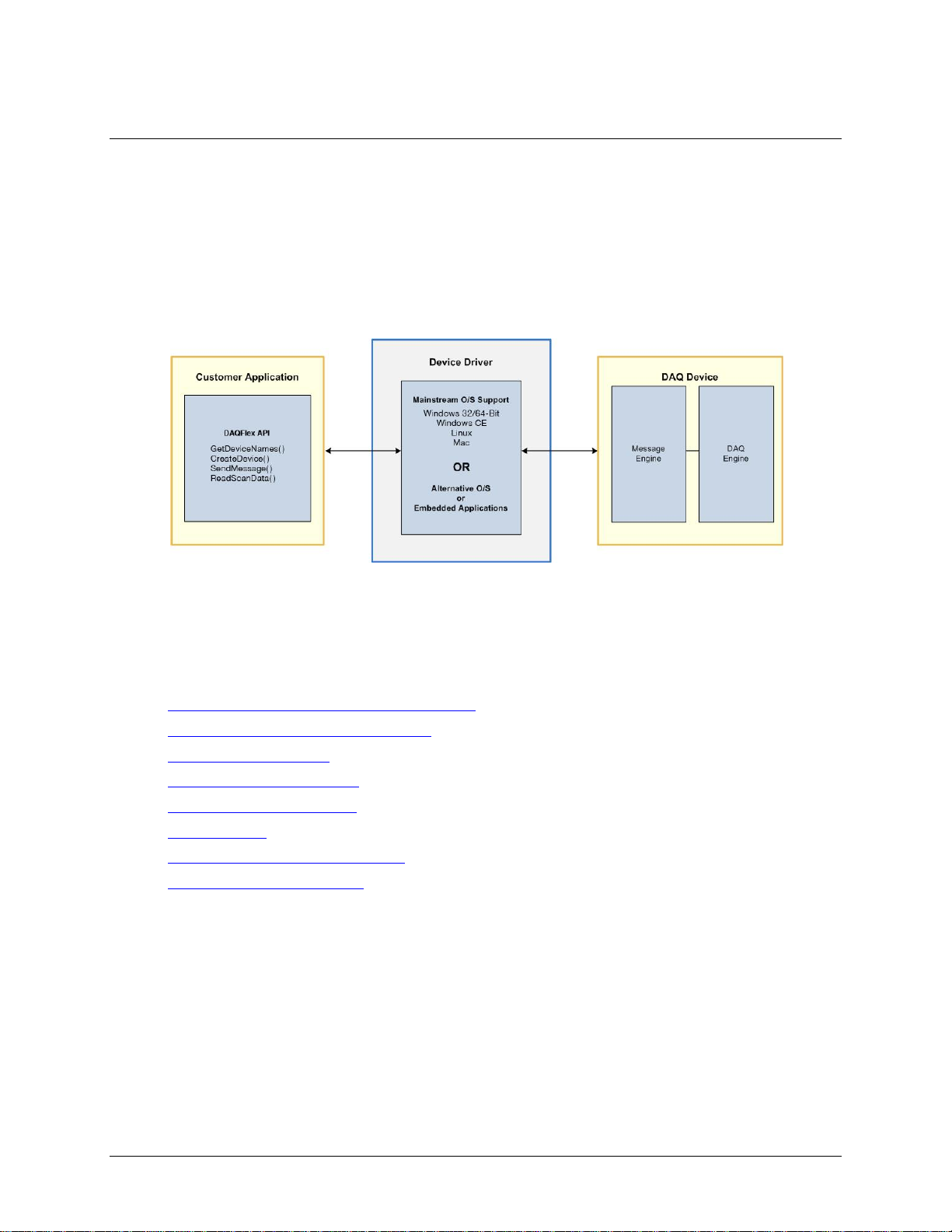
The DAQFlex framework consists of a software API, DAQFlex device driver, and the DAQ device message
engine. The message engine parses and converts the DAQFlex message-based command set into
DAQ-specific commands that control the device and process data.
Figure 1. DAQFlex Framework
A DAQFlex program sends DAQFlex methods to the driver. The driver sends the encapsulated messages
to the data acquisition device. The device interprets the message using the message engine, and sets its
corresponding attributes using the DAQ engine. The data acquisition device then returns the requested
data to the DAQFlex driver, which returns the data in an array (ScanData) to the program.
DAQFlex software includes the software API, device driver, FlexTest utility, and example programs.
Platform Support and Hardware Requirements
Installing the DAQFlex Software Library
Using DAQFlex Software
DAQFlex Software Reference
DAQFlex Message Reference
FlexTest Utility
C# and VB .NET Example programs
DAQFlex Hardware Reference
Platform support
You can run the DAQFlex communication protocol on a computer running one of the following operating
systems and software:
Microsoft Windows (32-bit or 64-bit)
o Windows 8
o Windows 7
o Windows Vista
o Windows XP
o Microsoft .NET® Framework 2.0 or later
6
Page 7

DAQFlex Software User's Guide Introducing DAQFlex Software
Microsoft Windows CE
Development requirements:
o Microsoft Windows XP/Vista operating system
o Microsoft Visual Studio 2008 or later
o Microsoft .NET Compact Framework 3.5
o Microsoft ActiveSync
Deployment requirements:
o Windows CE 5.0
o X86 or ARM CPU
o Microsoft .NET Compact Framework 3.5
o DaqFlex.dll
o Mcusb.dll
o Mcwinceusb.dll
Macintosh (32-bit or 64-bit)
o MAC OS X
o Leopard 10.5 or later
o Mono Framework 2.0 or later
o libusb user-mode driver version 1.0.0.0
Linux (32-bit or 64-bit)
o Linux (2.4 kernel or later)
o Mono Framework 2.0 or later
o libusb user-mode driver version 1.0.0.0
Hardware requirements
Intel Pentium 4, 1 GHz or higher
Minimum of 512 MG of RAM (1 GB or higher recommended)
Video card with 128 MB memory
Video display with 800 x 600 resolution or greater, and 256 colors or greater
Microsoft-compatible mouse
Installing the DAQFlex software library
DAQFlex software operates with standard drivers for Windows, Mac, and Linux. Follow the procedure
below specific to your operating system to install the DAQFlex software.
Windows 8, Windows 7, Windows Vista, and Windows XP
1. Go to the DAQFlex download page at www.mccdaq.com/DAQFlexDL and select the Windows 32/64-
bit option.
2. Run the Windows DAQFlex.exe installer file.
3. Follow the installer instructions.
Connect your DAQFlex device after installing the software. You can run the FlexTest.exe test application,
or build and run the C# or VB .NET example programs included in the installation using ExampleBuilder
or Visual Studio (version 2005 or later).
Refer to the C# and VB Example Programs chapter on page 96 for instructions on running the DAQFlex
example programs, and to the Hardware Reference chapter on page 98 for the API components and
messages supported by DAQFlex supported hardware.
7
Page 8

DAQFlex Software User's Guide Introducing DAQFlex Software
Windows CE
1. Go to the DAQFlex download page at www.mccdaq.com/DAQFlexDL and select the Windows CE
option.
2. Run the DAQFlex for Windows CE.msi installer file.
3. Follow the installer instructions.
4. After the DAQFlex software is installed, copy the Windows CE device drivers (mccusb.dll and
mccwinceusb.dll) from the DAQFlex for Windows CE\Drivers\ directory (\X86 or \XScale
folder) to the device's Windows directory.
Connect your DAQFlex device after installing the software. You can run the FlexTest.exe, or build and
run the C# or VB .NET example programs included in the installation using Visual Studio (version 2008
or later).
Refer to the C# and VB Example Programs chapter on page 96 for instructions on running the DAQFlex
example programs, and to the Hardware Reference chapter on page 98 for the API components and
messages supported by DAQFlex supported hardware.
Mac OS X
1. Go to the DAQFlex download page at www.mccdaq.com/DAQFlexDL and select the Mac OS option.
2. Run the DAQFlex installer package (DAQFlex.pkg).
3. Follow the installer instructions.
Connect your DAQFlex device after installing the software. You can run the FlexTest application located
in the /Applications/Measurement Computing/DAQFlex folder. Additionally, you can build and run
the example programs included in the installation using ExampleBuilder.
Refer to the C# and VB Example Programs chapter on page 96 for instructions on running the DAQFlex
example programs, and to the Hardware Reference chapter on page 98 for the API components and
messages supported by DAQFlex supported hardware.
Linux
1. Using your Software/Package manager, verify that the Mono framework (version 2.4 or later) and
the libusb user-mode driver are installed on your Linux system.
If these versions aren't listed, information on installing, updating, or adding software repositories to
your Software/Package manager can be found at the following links. Click here to go to the Mono
web site. Click here to go to the libusb web site.
2. As a root user, create a symbolic link to the libusb-1.0 shared object file. For example:
o ln -s /usr/lib/libusb-1.0.so.0/usr/lib/libusb-1.0.so
The actual file location may vary.
3. Extract the files from the DAQFlex-2.0.tar.gz archive file on the DAQFlex software CD using an
archive manager.
4. In a terminal window, set the current directory to DAQFlex/Source/DAQFlexAPI.
5. As a root user, run the following commands:
o make
o make install
6. Restart the system.
Connect your DAQFlex device after installing the software. You can run the FlexTest application by
running the command $ flextest from a terminal window. Additionally, you can build and run the C#
example programs included in the installation using MonoDevelop or the Mono command line
interpreter.
Refer to the C# and VB Example Programs chapter on page 96 for instructions on running the DAQFlex
example programs, and to the Hardware Reference chapter on page 98 for the API components and
messages supported by DAQFlex supported hardware.
8
Page 9

string[] deviceNames;
deviceNames = DaqDeviceManager.GetDeviceNames(DeviceNameFormat.NameAndSerno);
Dim deviceNames As String()
deviceNames = DaqDeviceManager.GetDeviceNames(DeviceNameFormat.NameAndSerno)
Member Name
Description
NameOnly
The returned values contain only the device name.
NameAndSerno
The return values contain the device name with the device serial number
formatted as "DeviceName::SerialNumber".
NameAndID
The return values contains the device name with the device's user-defined ID
formatted as "DeviceName::DeviceID".
NameSernoAndID
The return values contains the device name, the device serial number and the
device's user-defined ID formatted as "DeviceName::SerialNumber::DeviceID".
int deviceNumber = 0;
DaqDevice device;
string deviceName = deviceNames[deviceNumber];
device = DaqDeviceManager.CreateDevice(deviceName);
Chapter 2
Using DAQFlex Software
The following procedure describes how to program a DAQFlex-supported device with DAQFlex software.
1. Add a reference to the DAQFlex assembly to your project.
o In Visual Studio and MonoDevelop, this assembly is listed under the .NET tab of the Add
Reference dialog as DAQFlex API.
If your project is a C# project, add the following statement to your source file:
using MeasurementComputing.DAQFlex;
2. Get a list of device names using the static method GetDeviceNames():
C#
VB
GetDeviceNames gets the names of DAQFlex devices detected by the DAQFlex API. DeviceNameFormat
is an enumeration that specifies the format of the returned values. This enumeration defines four
different formats:
Note: Each DAQFlex API method will throw an exception if an error occurs, and should be enclosed
within a Try/Catch block.
3. Get a device object using the static method CreateDevice():
C#
9
Page 10

DAQFlex Software User's Guide Using DAQFlex Software
Dim deviceNumber As Integer
Dim device As DaqDevice
Dim deviceName As String
deviceNumber = 0
deviceName = deviceNames(deviceNumber)
device = DaqDeviceManager.CreateDevice(deviceName)
DaqResponse response;
response = device.SendMessage("AI{0}:RANGE=BIP10V"); // set the input range for channel 0
response = device.SendMessage("?AI{0}:VALUE"); // read a single value from channel 0
Dim response As DaqResponse
response = device.SendMessage("AI{0}:RANGE=BIP10V") ' set the input range for channel 0
response = device.SendMessage("?AI{0}:VALUE") ' read a single value from channel 0
string value = response.ToString();
Dim value As String
value = response.ToString()
double value = response.ToValue();
Dim value As Double
value = response.ToValue()
DaqDeviceManager.ReleaseDevice(device);
DaqDeviceManager.ReleaseDevice(device)
VB
4. Once you have a DaqDevice object, use the SendMessage() method to program your DAQFlex-
supported device.
C#
VB
The DaqResponse object contains a method for getting the response as a string and a method for
getting the response as a numeric.
To get the response as a string, use the ToString() method:
C#
VB
To get the response as a numeric, use the ToValue() method:
C#
VB
If the response does not contain a numeric value, ToValue() returns Double.NaN.
When you no longer need the DaqDevice object, you can release it by calling the ReleaseDevice()
method:
C#
VB
10
Page 11

DAQFlex Software User's Guide Using DAQFlex Software
Reading and writing software-paced I/O
The following examples demonstrate how to perform asynchronous single-point I/O using DAQFlex
software:
Reading an analog input channel
Writing to an analog output channel
Reading a digital bit
Writing to a digital bit
Reading a digital port
Writing to a digital port
Reading a counter input channel
11
Page 12

DAQFlex Software User's Guide Using DAQFlex Software
// Read the value of analog input channel 0
String[] Devices;
DaqDevice MyDevice;
DaqResponse Response;
try
{
// Get a list of message-based DAQ devices
Devices = DaqDeviceManager.GetDeviceNames(DeviceNameFormat.NameAndSerno);
// Get a DaqDevice object for device 0
MyDevice = DaqDeviceManager.CreateDevice(Devices[0]);
// Send device messages using the DaqDevice object
MyDevice.SendMessage("AI{0}:RANGE=BIP10V");
MyDevice.SendMessage("AI:CAL=ENABLE");
MyDevice.SendMessage("AI:SCALE=ENABLE");
// Read and display the daq response
Response = MyDevice.SendMessage("?AI{0}:VALUE");
label1.Text = Response.ToString();
}
catch (Exception ex)
{
// handle error
label1.Text = ex.Message;
}
' Read the value of analog input channel 0
Dim Devices As String ()
Dim MyDevice As DaqDevice
Dim Response As DaqResponse
Try
' Get a list of message-based DAQ devices
Devices = DaqDeviceManager.GetDeviceNames(DeviceNameFormat.NameAndSerno)
' Get a DaqDevice object for device 0
MyDevice = DaqDeviceManager.CreateDevice(Devices(0))
' Send device messages using the DaqDevice object
MyDevice.SendMessage("AI{0}:RANGE=BIP10V")
MyDevice.SendMessage("AI:CAL=ENABLE")
MyDevice.SendMessage("AI:SCALE=ENABLE")
' Read and display the daq response
Response = MyDevice.SendMessage("?AI{0}:VALUE")
Label1.Text = Response.ToString()
Catch Ex As Exception
' handle error
Label1.Text = Ex.Message()
End Try
Reading an analog input channel
C#
VB
12
Page 13

DAQFlex Software User's Guide Using DAQFlex Software
// Write a value to analog output channel 0
String[] Devices;
DaqDevice MyDevice;
try
{
// Get a list of message-based DAQ devices
Devices = DaqDeviceManager.GetDeviceNames(DeviceNameFormat.NameAndSerno);
// Get a DaqDevice object for device 0
MyDevice = DaqDeviceManager.CreateDevice(Devices[0]);
// Send device messages
MyDevice.SendMessage("AO{0}:RANGE=BIP10V");
MyDevice.SendMessage("AO:CAL=ENABLE");
MyDevice.SendMessage("AO:SCALE=ENABLE");
MyDevice.SendMessage("AO{0}:VALUE=2.53");
}
catch (Exception ex)
{
// handle error
label1.Text = ex.Message;
}
' Write a value to analog output channel 0
Dim Devices As String()
Dim MyDevice As DaqDevice
Try
' Get a list of message-based DAQ devices
Devices = DaqDeviceManager.GetDeviceNames(DeviceNameFormat.NameAndSerno)
' Get a DaqDevice object for device 0
MyDevice = DaqDeviceManager.CreateDevice(Devices(0))
' Send device messages
MyDevice.SendMessage("AO{0}:RANGE=BIP10V")
MyDevice.SendMessage("AO:CAL=ENABLE")
MyDevice.SendMessage("AO:SCALE=ENABLE")
MyDevice.SendMessage("AO{0}:VALUE=2.53")
Catch Ex As Exception
' handle error
Label1.Text = Ex.Message
End Try
Writing to an analog output channel
C#
VB
13
Page 14

DAQFlex Software User's Guide Using DAQFlex Software
// Read the value of digital port 0, bit 0
String[] Devices;
DaqDevice MyDevice;
DaqResponse Response;
try
{
// Get a list of message-based DAQ devices
Devices = DaqDeviceManager.GetDeviceNames(DeviceNameFormat.NameAndSerno);
// Get a DaqDevice object for device 0
MyDevice = DaqDeviceManager.CreateDevice(Devices[0]);
// Read and display the daq response
MyDevice.SendMessage("DIO{0/0}:DIR=IN");
Response = MyDevice.SendMessage("?DIO{0/0}:VALUE");
label1.Text = Response.ToString();
}
catch (Exception ex)
{
// handle error
label1.Text = ex.Message;
}
' Read the value of digital port 0, bit 0
Dim MyDevice As DaqDevice
Dim Response As DaqResponse
Dim Devices As String ()
Try
' Get a list of message-based DAQ devices
Devices = DaqDeviceManager.GetDeviceNames(DeviceNameFormat.NameAndSerno)
' Get a DaqDevice object for device 0
MyDevice = DaqDeviceManager.CreateDevice(Devices(0))
' Read and display the daq response
MyDevice.SendMessage("DIO{0/0}:DIR=IN")
Response = MyDevice.SendMessage("?DIO{0/0}:VALUE")
Label1.Text = Response.ToString()
Catch Ex As Exception
' handle error
Label1.Text = Ex.Message
End Try
Reading a digital bit
C#
VB
14
Page 15

DAQFlex Software User's Guide Using DAQFlex Software
// Write a value to digital port 0, bit 0
String[] Devices;
DaqDevice MyDevice;
DaqResponse Response;
try
{
// Get a list of message-based DAQ devices
Devices = DaqDeviceManager.GetDeviceNames(DeviceNameFormat.NameAndSerno);
// Get a DaqDevice object for device 0
MyDevice = DaqDeviceManager.CreateDevice(Devices[0]);
// Send device messages
MyDevice.SendMessage("DIO{0/0}:DIR=
MyDevice.SendMessage("DIO{0/0}:VALUE=
label1.Text = response.ToString();
}
catch (Exception ex)
}
// handle error
label1.Text = ex.Message;
}
' Write a value to digital port 0, bit 0
Dim MyDevice As DaqDevice
Dim Response As DaqResponse
Dim Devices As String ()
Try
' Get a list of message-based DAQ devices
Devices = DaqDeviceManager.GetDeviceNames(DeviceNameFormat.NameAndSerno)
' Get a DaqDevice object for device 0
MyDevice = DaqDeviceManager.CreateDevice(Devices(0))
' Send device messages
MyDevice.SendMessage("DIO{0/0}:DIR=
Response = MyDevice.SendMessage("DIO{0/0}:VALUE=
Label1.Text = Response.ToString
Catch Ex As Exception
' handle error
Label1.Text = Ex.Message
End Try
Writing to a digital bit
C#
VB
15
Page 16

DAQFlex Software User's Guide Using DAQFlex Software
// Read the value of digital port 0
String[] Devices;
DaqDevice MyDevice;
DaqResponse Response;
try
{
// Get a list of message-based DAQ devices
Devices = DaqDeviceManager.GetDeviceNames(DeviceNameFormat.NameAndSerno);
// Get a DaqDevice object for device 0
MyDevice = DaqDeviceManager.CreateDevice(Devices[0]);
// Send device messages
MyDevice.SendMessage("DIO{0}:DIR=IN");
// Read and display the daq response
Response = MyDevice.SendMessage("?DIO{0}:VALUE");
Label1.Text = Response.ToString();
}
catch (Exception ex)
{
// handle error
label1.Text = ex.Message;
}
' Read the value of digital port 0
Dim MyDevice As DaqDevice
Dim Response As DaqResponse
Dim Devices As String ()
Try
' Get a list of message-based DAQ devices
Devices = DaqDeviceManager.GetDeviceNames(DeviceNameFormat.NameAndSerno)
' Get a DaqDevice object for device 0
MyDevice = DaqDeviceManager.CreateDevice(Devices(0))
' Send device messages
MyDevice.SendMessage("DIO{0}:DIR=IN")
' Read and display the daq response
Response = MyDevice.SendMessage("?DIO{0}:VALUE")
Label1.Text = Response.ToString()
Catch Ex As Exception
' handle error
Label1.Text = Ex.Message
End Try
Reading a digital port
C#
VB
16
Page 17

DAQFlex Software User's Guide Using DAQFlex Software
// Write a value to digital port 0
String[] Devices;
DaqDevice MyDevice;
DaqResponse Response;
try
{
// Get a list of message-based DAQ devices
Devices = DaqDeviceManager.GetDeviceNames(DeviceNameFormat.NameAndSerno);
// Get a DaqDevice object for device 0
MyDevice = DaqDeviceManager.CreateDevice(Devices[0]);
// Send device messages
MyDevice.SendMessage("DIO{0}:DIR=OUT");
MyDevice.SendMessage("DIO{0}:VALUE=128");
label1.Text = response.ToString();
}
catch (Exception ex)
}
// handle error
label1.Text = ex.Message;
}
' Write a value to digital port 0
Dim MyDevice As DaqDevice
Dim Response As DaqResponse
Dim Devices As String ()
Try
' Get a list of message-based DAQ devices
Devices = DaqDeviceManager.GetDeviceNames(DeviceNameFormat.NameAndSerno)
' Get a DaqDevice object for device 0
MyDevice = DaqDeviceManager.CreateDevice(Devices(0))
' Send device messages
MyDevice.SendMessage("DIO{0}:DIR=OUT")
Response = MyDevice.SendMessage("DIO{0}:VALUE=128")
Label1.Text = Response.ToString
Catch Ex As Exception
' handle error
Label1.Text = Ex.Message
End Try
Writing to a digital port
C#
VB
17
Page 18

DAQFlex Software User's Guide Using DAQFlex Software
// Read counter channel 0
String[] Devices;
DaqDevice MyDevice;
DaqResponse Response;
try
{
// Get a list of message-based DAQ devices
Devices = DaqDeviceManager.GetDeviceNames(DeviceNameFormat.NameAndSerno);
// Get a DaqDevice object for device 0
MyDevice = DaqDeviceManager.CreateDevice(Devices(0));
// Start the counter
MyDevice.SendMessage("CTR{0}:VALUE=0");
MyDevice.SendMessage("CTR{0}:START");
// Read and display the daq response
for(int i = 1;i<=10;i++)
{
System.Threading.Thread.Sleep(750);
Response = MyDevice.SendMessage("?CTR{0}:VALUE");
label1.Text = Response.ToString();
Application.DoEvents();
}
// Stop the counter
MyDevice.SendMessage("CTR{0}:STOP");
}
catch (Exception ex)
{
// handle error
label1.Text = ex.Message;
}
' Read counter channel 0
Dim MyDevice As DaqDevice
Dim Response As DaqResponse
Dim Devices As String ()
Try
' Get a list of message-based DAQ devices
Devices = DaqDeviceManager.GetDeviceNames(DeviceNameFormat.NameAndSerno)
' Get a DaqDevice object for device 0
MyDevice = DaqDeviceManager.CreateDevice(Devices(0))
Dim I As Integer
' Start the counter
MyDevice.SendMessage("CTR{0}:VALUE=0")
MyDevice.SendMessage("CTR{0}:START")
' Read and display the daq response
For I = 1 To 10
System.Threading.Thread.Sleep(750)
Response = MyDevice.SendMessage("?CTR{0}:VALUE")
Label1.Text = Response.ToString()
Application.DoEvents()
Next
Reading a counter input channel
C#
VB
18
Page 19

DAQFlex Software User's Guide Using DAQFlex Software
' Stop the counter
MyDevice.SendMessage("CTR{0}:STOP")
Catch Ex As Exception
' handle error
Label1.Text = Ex.Message
End Try
try
{
double[,] scanData;
string[] names = DaqDeviceManager.GetDeviceNames(DeviceNameFormat.NameAndSerno);
DaqDevice device = DaqDeviceManager.CreateDevice(names[0]);
device.SendMessage("AISCAN:LOWCHAN=0");
device.SendMessage("AISCAN:HIGHCHAN=0");
device.SendMessage("AISCAN:RATE=1000");
device.SendMessage("AISCAN:SAMPLES=5000");
device.SendMessage("AISCAN:START");
scanData = device.ReadScanData(5000, 0);
}
catch (Exception ex)
{
Console.WriteLine(ex.Message);
}
Try
Dim ScanData As Double(,)
Dim Names As String()
Dim Device As DaqDevice
Names = DaqDeviceManager.GetDeviceNames(DeviceNameFormat.NameAndSerno)
Device = DaqDeviceManager.CreateDevice(Names(0))
Device.SendMessage("AISCAN:LOWCHAN=0")
Device.SendMessage("AISCAN:HIGHCHAN=0")
Device.SendMessage("AISCAN:RATE=1000")
Device.SendMessage("AISCAN:SAMPLES=5000")
Device.SendMessage("AISCAN:START")
ScanData = Device.ReadScanData(5000, 0)
Catch ex As Exception
Console.WriteLine(ex.Message)
End Try
Reading hardware-paced I/O
The basic approach to programming analog input scans is to set the device's scan properties, send the
START command, and call the ReadScanData() method. The following examples show how to program a
basic input scan.
C#
VB
19
Page 20
DAQFlex Software User's Guide Using DAQFlex Software
Device.EnableCallback(callbackMethod, callbackType, callbackCount);
Device.EnableCallback(Addressof CallbackMethod, CallbackType, CallbackCount)
void CallbackMethod(ErrorCodes errorCode, CallbackType callbackType, object callbackData)
Sub CallbackMethod(ByVal errorCode As ErrorCodes, ByVal callbackType As CallbackType,
_ ByVal callbackData As Object)
Member Name
Description
OnDataAvailable
Specifies that the callback method will be invoked when a specified
number of samples becomes available for reading.
OnInputScanComplete
Specifies that the callback method will be invoked when a finite scan has
complete or when a continuous scan is stopped.
OnInputScanError
Specifies that the callback method will be invoked when an input scan
error occurs.
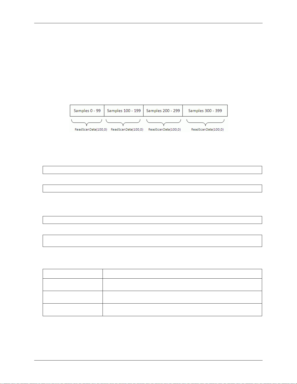
ReadScanData() parameters
The first parameter to the ReadScanData method is the number of samples to read.
The second parameter is a time out value in milli-seconds. A value of 0 indicates no timeout
specified.
The ReadScanData method is synchronous, and will return when the number of requested samples are
available for reading. When the number of requested samples are available, the DAQFlex software
copies the requested number of samples from an internal buffer to a new array of data. The DAQFlex
software keeps track of the buffer index so that multiple calls to ReadScanData always return
contiguous data.
Internal buffer
An alternative method for reading scan data is to enable a user-defined callback method. When you
enable a callback method, the DAQFlex software invokes your user-defined method when a specified
number of samples are available for reading, when a scan completes, or if a scan error occurs. This is
done using the EnableCallback method as shown below:
C#
VB
The callbackMethod is the name of the method that will be invoked by the DAQFlex software. The
callbackMethod is a class method that must have the following form:
C#
VB
The callbackType is an enumeration that defines when the callback method will be invoked.
CallbackType
Only one callback method can be specified for each callback type. When the callback type is set to
OnDataAvailable, set the callbackData parameter to the number of samples you wish to receive in the
callback method. When the callback type is set to OnInputScanComplete or OnInputScanError, set the
callbackData parameter to null or Nothing.
20
Page 21

DAQFlex Software User's Guide Using DAQFlex Software
try
{
double[,] scanData;
string[] names = DaqDeviceManager.GetDeviceNames(DeviceNameFormat.NameAndSerno);
DaqDevice device = DaqDeviceManager.CreateDevice(names[0]);
device.EnableCallback(OnReadScanData, CallbackType.OnDataAvailable, 1000);
device.EnableCallback(OnReadScanData, CallbackType.OnScanComplete, null);
device.SendMessage("AISCAN:LOWCHAN=0");
device.SendMessage("AISCAN:HIGHCHAN=0");
device.SendMessage("AISCAN:RATE=1000");
device.SendMessage("AISCAN:SAMPLES=5000");
device.SendMessage("AISCAN:START");
}
catch (Exception ex)
{
Console.WriteLine(ex.Message);
}
protected void OnReadScanData(ErrorCodes errorCode, CallbackType callbackType,
object callbackData)
{
try
{
int availableSamples = (int)callbackData;
double[,] scanData = device.ReadScanData(availableSamples, 0);
}
catch (Exception ex)
{
Console.WriteLine(ex.Message);
}
}
The following are examples of reading scan data using a callback method:
C#
21
Page 22

DAQFlex Software User's Guide Using DAQFlex Software
Try
Dim ScanData As Double(,)
Dim Names As String()
Dim Device As DaqDevice
Names = DaqDeviceManager.GetDeviceNames(DeviceNameFormat.NameAndSerno)
Device = DaqDeviceManager.CreateDevice(Names(0))
Device.EnableCallback(AddressOf OnReadScanData, CallbackType.OnDataAvailable,
1000)
Device.EnableCallback(AddressOf OnReadScanData, CallbackType.OnScanComplete,
Nothing)
Device.SendMessage("AISCAN:LOWCHAN=0")
Device.SendMessage("AISCAN:HIGHCHAN=0")
Device.SendMessage("AISCAN:RATE=1000")
Device.SendMessage("AISCAN:SAMPLES=5000")
Device.SendMessage("AISCAN:START")
Catch ex As Exception
Console.WriteLine(ex.Message)
End Try
Protected Sub ReadScanData(ByVal errorCode As ErrorCodes, ByVal callbackType As
CallbackType, _ ByVal callbackData As Object)
Try
Dim AvailableSamples As Integer
Dim ScanData As Double(,)
AvailableSamples = DirectCast(callbackData, Integer)
ScanData = Device.ReadScanData(AvailableSamples, 0)
Catch ex As Exception
Console.WriteLine(ex.Message)
End Try
try
{
double[,] scanData = new double[1, 5000];
string[] names = DaqDeviceManager.GetDeviceNames(DeviceNameFormat.NameAndSerno);
DaqDevice device = DaqDeviceManager.CreateDevice(names[0]);
// fill scanData with data
device.SendMessage("AOSCAN:LOWCHAN=0");
device.SendMessage("AOSCAN:HIGHCHAN=0");
device.SendMessage("AOSCAN:RATE=1000");
device.SendMessage("AOSCAN:SAMPLES=5000");
device.SendMessage("AOSCAN:BUFSIZE=5000");
int timeOut = 0;
device.WriteScanData(scanData, 5000, timeOut);
device.SendMessage("AOSCAN:START");
}
VB
The basic approach to programming analog output scans is to set the device's output scan properties,
call the WriteScanData() method, and send the START command. The following examples show how to
program a basic output scan.
C#
22
Writing hardware-paced I/O
Page 23
DAQFlex Software User's Guide Using DAQFlex Software
catch (Exception ex)
{
Console.WriteLine(ex.Message);
}
Try
Dim ScanData As Double(,)
Dim Names As String()
Dim Device As DaqDevice
Dim TimeOut As Integer
Names = DaqDeviceManager.GetDeviceNames(DeviceNameFormat.NameAndSerno)
Device = DaqDeviceManager.CreateDevice(Names(0))
Device.SendMessage("AOSCAN:LOWCHAN=0")
Device.SendMessage("AOSCAN:HIGHCHAN=0")
Device.SendMessage("AOSCAN:RATE=1000")
Device.SendMessage("AOSCAN:SAMPLES=5000")
Device.SendMessage("AOSCAN:BUFSIZE=5000")
int TimeOut = 0
Device.WriteScanData(ScanData, 5000, TimeOut)
Device.SendMessage("AOSCAN:START")
Catch ex As Exception
Console.WriteLine(ex.Message)
End Try
VB
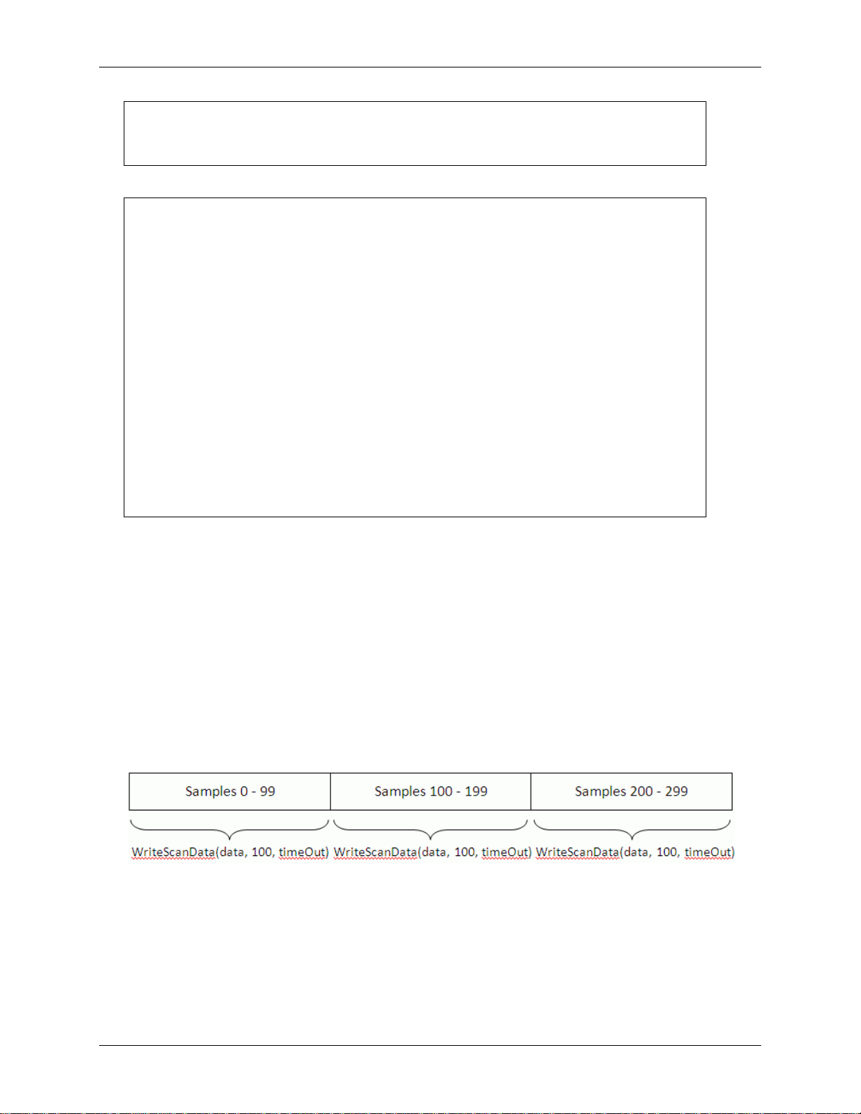
WriteScanData() parameters
The first parameter to the WriteScanData method is the array containing the output scan data.
The second parameter is the number of samples to write.
The last parameter is a timeout value in milliseconds.
The WriteScanData method is synchronous, and will return when the number of samples specified have
been written to the device’s output buffer.
Each time the WriteScanData method is called, the data is written to an internal buffer starting at the
point after the last sample was written. When an output scan completes or is stopped, the write index is
reset to the beginning of the buffer.
Internal buffer
23
Page 24

C#:
static string[] GetDeviceNames(DeviceNameFormat format);
VB:
Shared Function GetDeviceNames(ByVal format As DeviceNameFormat) As
String()
Value
Return string format
NameOnly
"Device name"
NameAndSerno
"Device name::Device serial number"
NameAndID
"Device name::Device ID"
NameSernoAndID
"Device name::Device serial number::Device ID"
Chapter 3
DAQFlex Software Reference
The DAQFlex Software API is an open source library that implements a simple message-based protocol
consisting of text-based commands, or messages. The API is written in C#, is designed for cross
platform portability, and does not require a separate configuration utility or a configuration file.
DAQFlex Software API contains two classes:
DaqDeviceManager class
DaqDevice class
DaqDeviceManager class
The DaqDeviceManager class includes the following methods:
GetDeviceNames() – gets a list of devices that support the message-based protocol.
CreateDevice() – creates a DaqDevice object, which contains the methods used to communicate
with a DAQ device.
ReleaseDevice() – frees the resources associated with a DaqDevice object.
DaqDeviceManager.GetDeviceNames()
Gets a list of DAQ devices that support the message-based protocol.
Parameter
format
The format to use for a device name. This parameter is a DeviceNameFormat enumeration. The
enumeration values and the format of the return strings are listed below:
Return value
An array of strings containing the device names of all DAQ devices that support the message-based
protocol.
Remarks
The values contained in the array can be used to create a DaqDevice object for the device that you
want to program.
The DaqDevice object is created using the DaqDeviceManager CreateDevice static method.
With the DaqDevice object, all DAQ operations are configured using one API method called
SendMessage() rather than using multiple operation-specific methods.
The NameOnly format is not useful if multiple devices of the same type are connected, since the
application won't be able to differentiate between one device and the other. If you are using
multiple devices of the same type, then use one of the other formats.
24
Page 25

DAQFlex Software User's Guide DAQFlex Software Reference
C#:
static CreateDevice(string deviceName);
VB:
Shared Function CreateDevice(ByVal deviceName As String) As DaqDevice
try
{
MyDevice = DaqDeviceManager.CreateDevice(deviceName);
}
catch (Exception ex)
{
// handle exception
}
Try
MyDevice = DaqDeviceManager.CreateDevice(deviceName)
Catch Ex As Exception
' handle exception
End Try
If using a device that does not have an ID assigned, you must use the NameOnly or NameAndSerno
format with the DaqDeviceManager.CreateDevice() method in order to create the device. A device
with no ID will not be created when using the NameAndID and NameSernoAndID format with
CreateDevice().
DaqDeviceManager.CreateDevice()
Creates a DaqDevice object. The DaqDevice object contains the methods used to configure, read data
from, or write data to a device. With the DaqDevice object, all DAQ operations are configured using one
API method called DaqDevice.SendMessage() rather than using multiple operation-specific methods.
SendMessage() takes a single parameter called message. This parameter is a text-based command that
the DAQ device parses to configure a particular operation.
Parameter
deviceName
One of the device names returned by the DaqDeviceManager.GetDevicenames() method.
Return value
An instance of a DaqDevice object.
Remarks
Depending on the DeviceNameFormat, the CreateDevice() method creates a DaqDevice object for
the device whose name, name and serial number, name and id, or name, serial number and id are
contained in the deviceName parameter.
The resources associated with the DaqDevice object can be freed by calling the ReleaseDevice()
method.
The CreateDevice() method can only be called once for a specific device, unless the ReleaseDevice()
method is called.
If CreateDevice() is called more than once for a specific device without calling ReleaseDevice(), the
DaqDevice object throws an exception, indicating that a driver handle has already been created for
the device.
Refer to the following sample code:
C#
VB
25
Page 26

DAQFlex Software User's Guide DAQFlex Software Reference
C#:
static void ReleaseDevice(DaqDevice device);
VB:
Shared Sub ReleaseDevice(ByVal device As DaqDevice)
C#:
DaqResponse SendMessage (string message);
VB:
Function SendMessage (ByVal Message as String) As DaqResponse
DaqDeviceManager.ReleaseDevice()
Frees the resources associated with a DaqDevice object.
Parameter
Device
A DaqDevice object created by the CreateDevice() method.
DaqDevice class
The DaqDevice class includes the following methods:
SendMessage() – takes a single text-based command that the DAQ device parses to configure a
particular operation.
ReadScanData() – reads scan data.
WriteScanData() – outputs scan data.
EnableCallback() – enables a user-defined callback method to be invoked when a certain condition
is met. This method is used in conjunction with input scan operations.
DisableCallback() – the condition that invokes the callback method.
GetErrorMessage() – gets the error message associated with the error code that is passed to the
user-defined callback.
GetSupportedMessages() – returns a list of messages supported by a DAQ component.
DaqDevice.SendMessage()
Configures DAQ operations. This method takes a single text-based command that the DAQ device
parses to configure a particular operation.
Parameter
Message
The text-based message to send to the device.
Return value
The device response as an instance of a DaqResponse object.
Remarks
Message is a string containing a text-based command supported by the device, and Response is a
DaqResponse object containing the device's response.
The DaqResponse object includes two methods:
ToString(): gets the response as a string, for example "AI{0}:VALUE=139".
ToValue(): gets the response as a numeric value, for example "139.0000".
All messages provide a string response, but not all messages provide a numeric response. For those
messages that do not provide a numeric response, the numeric value is set to NaN (not a number).
26
Page 27

DAQFlex Software User's Guide DAQFlex Software Reference
try
{
DaqResponse response = MyDevice.SendMessage(message);
label1.Text = response.ToString();
}
Catch (Exception ex)
{
// handle exception
label1.Text = ex.Message;
}
Try
DaqResponse Response = MyDevice.SendMessage(Message)
Label1.Text = Response.ToString()
Catch Ex As Exception
' handle exception
Label1.Text = Ex.Message;
End Try
C#:
double[,] ReadScanData(int samplesRequested, int timeOut);
VB:
Function ReadScanData(ByVal samplesRequested As Integer, ByVal timeOut
As Integer) As Double(,)
The ToString method has additional overloads that accept formatting parameters. The overloads are
ToString(string format), ToString(IFormatProvider provider) and ToString(string format,
IFormatProvider provider). The overloads can be used to format the numeric part of a response, if
present. If the response does not contain a numeric, these overloads are ignored.
If an error occurs while sending a message to a device, the SendMessage method will throw an
exception rather than returning an error code. This means the application should encapsulate calls
to SendMessage within a try/catch block.
Refer to the following sample code.
C#
VB
DaqDevice.ReadScanData()
Reads data for a scan operation.
Parameter
samplesRequested
The number of samples per channel to read.
timeOut
The number of milliseconds to wait for the samples requested to become available.
Return value
An array of data samples read from the device.
Remarks
The DAQFlex library always performs scan operations in the background, but ReadScanData()
always runs in the foreground. When called, ReadScanData() returns control to the application that
called it when the number of samples requested has been read. When timeOut is non-zero, if the
number of samples requested isn’t available within the time specified by timeOut, an exception is
thrown. The DAQFlex library manages all memory allocation and array indexing so the application
doesn't have to.
27
Page 28

DAQFlex Software User's Guide DAQFlex Software Reference
C#:
void WriteScanData(double[,] scanData, int numberOfSamplesPerChannel,
int timeOut);
VB:
Sub WriteScanData(ByVal ScanData(,) As Double, ByVal
NumberOfSamplesPerChannel As Integer, ByVal TimeOut As Integer)
C#:
void EnableCallback(ErrorCodes errorCode, InputScanCallbackDelegate
callback, CallbackType callbackType, Object callbackData
VB:
Sub EnableCallback(ByVal errorCode as ErrorCodes, ByVal callback as
InputScanCallbackDelegate, ByVal callbackType As CallbackType, ByVal
callbackData As Object)
DaqDevice.WriteScanData()
Outputs scan data.
Parameter
scanData
Array of data samples to output.
numberOfSamplesPerChannel
The number of data samples per channel to transfer from the scanData array to the device's output
buffer.
timeOut
The number of milliseconds to wait for available space in the buffer to write to. This only takes
effect when an output scan is running.
Remarks
WriteScanData may be called while a scan is running. However, the maximum number of total
samples must be less than or equal to half the number of samples for which the buffer is allocated.
Set the buffer size with the "AOSCAN:BUFSIZE" message.
DaqDevice.EnableCallback()
Enables a user-defined callback method to be invoked when a certain condition is met.
Parameter
callback
The method to be invoked when the condition specified by callbackType is met. Refer to
InputScanCallback Delegate on page 29 for the format of the method.
callbackType
The condition that invokes the callback method. Callback types are defined by the CallbackType
enumeration. The supported types are:
o CallbackType.OnDataAvailable – Invokes the callback method when the number of samples
available for reading data is ≥ the number of samples specified by the callbackData parameter.
o CallbackType.OnInputScanComplete – Invokes the callback method when an input scan
completes or is stopped.
o CallbackType.OnInputScanError – Invokes the callback method when an input scan error
occurs.
callbackData
When callbackType is set to OnDataAvailable, set callbackData to the number of samples per
channel to acquire before invoking the user-defined callback method. When callbackType is set to
OnInputScanComplete or OnInputScanError, set callbackData to null or Nothing.
28
Page 29

DAQFlex Software User's Guide DAQFlex Software Reference
C#:
public delegate void
InputScanCallbackDelegate(MeasurementComputing.DAQFlex.ErrorCodes
errorCode, MeasurementComputing.DAQFlex.CallbackType callbackType,
object callbackData)
VB:
Public Delegate Sub InputScanCallbackDelegate(ByVal errorCode As
MeasurementComputing.DAQFlex.ErrorCodes, ByVal callbackType As
MeasurementComputing.DAQFlex.CallbackType, ByVal callbackData As
Object)
C#:
void DisableCallback(CallbackType callbackType)
VB:
Sub DisableCallback(ByVal callbackType As CallbackType)
C#:
string GetErrorMessage(ErrorCodes errorCode)
VB:
Function GetErrorMessage(ByVal errorCode As ErrorCodes)
Return value
The value of callbackType.
Remarks
This method is used in conjunction with input scan operations.
EnableCallback may be called once for each callback type. If it is called more than once for the
sample callback type, a DaqException is thrown.
InputScanCallback Delegate
A delegate is a data structure that refers either to a static method, or to a class instance and an
instance method of that class. You call the delegate by passing either its address or a pointer to the
delegate to the callback parameter of the EnableCallback() method.
DaqDevice.DisableCallback()
Disables the invocation of the user-defined callback method associated with the callback type.
Parameter
callbackType
The callback type to disable.
DaqDevice.GetErrorMessage()
Gets the error message associated with the error code that is passed to the user-defined callback.
Parameter
errorCode
The error code that was passed to the user-defined callback method.
Return value
The error message associated with the error code passed to the user-defined callback method.
29
Page 30

DAQFlex Software User's Guide DAQFlex Software Reference
C#:
public List<string> GetSupportedMessages(string daqComponent);
VB:
Function GetSupportedMessages(ByVal daqComponent As String) As List(Of
String)
DaqDevice.GetSupportedMessages()
Gets the messages supported by a DAQ component.
Parameter
daqComponent
A DAQ component, such as AISCAN, DEV, TMR, and so on.
Return value
A list of messages supported by the daqComponent parameter.
30
Page 31

Chapter 4
DAQFlex Message Reference
The software messages that you send to a DAQFlex supported device are text-based commands. Each
message pertains to a specific DAQ component. A DAQ component is a device element that
encapsulates a DAQ subsystem which has multiple properties or commands associated with it.
DAQFlex components
A DAQ component is a device element that encapsulates a DAQ subsystem which has multiple
properties or commands associated with it. The DAQFlex API defines the following DAQ components:
DEV — encapsulates device-level operations
AI — encapsulates single-point analog input operations
AICAL — encapsulates analog input self-calibration
AIQUEUE — encapsulates analog input gain queue operations
AISCAN — encapsulates analog input scanning operations
AITRIG — encapsulates analog input triggering operations
AO — encapsulates single-point analog output operations
AOCAL — encapsulates analog output self-calibration
AOSCAN — encapsulates analog output scanning operations
AOTRIG — encapsulates analog output triggering operations
DIO — encapsulates digital I/O operations
CTR — encapsulates counter input operations
TMR — encapsulates timer output operations
Each component has one or more properties associated with it. Each property supports one or more
text-based commands, or messages. These messages are used to communicate with DAQFlexsupported hardware.
DAQFlex supports two types of messages:
Device programming messages configure or retrieve a device property value.
Device reflection messages retrieve information about a device capability, such as the maximum
scan rate or support for an external clock.
31
Page 32

DAQFlex Software User's Guide DAQFlex Message Reference – Programming messages – AI
Components for
programming a device
Description
AI
Sets and gets property values for analog input channels.
AICAL
Sets and gets property values for calibrating analog inputs.
AIQUEUE
Sets and gets property values for the analog input gain queue.
AISCAN
Sets and gets property values when scanning analog input channels.
AITRIG
Sets and gets analog input trigger property values.
AO
Sets and gets property values for analog output channels
AOCAL
Sets and gets property values for calibrating analog outputs.
AOSCAN
Sets and gets property values when scanning analog output channels.
DEV
Sets and gets device property values.
DIO
Sets and gets property values for digital I/O channels.
CTR
Sets and gets property values for counter channels.
TMR
Sets and gets property values for timer output channels.
Message
"?AI"
Response
"AI=value"
value
The number of A/D channels on the device.
Message
"AI:ADCAL/START"
Response
"AI:ADCAL/START"
Programming messages
Device programming messages are used to get and set device properties. Programming messages that
query a device property always start with the ? character.
Click on a component name below for the string messages, device responses, and property values
supported by the component.
AI
Sets and gets property values for analog input channels.
Refer to the device-specific information in the Hardware Reference section for the component properties
and commands supported by each DAQ device.
Properties
ADCAL, CAL, CHMODE, CJC, DATARATE, OFFSET, RANGE, RES, SCALE, SENSOR, SLOPE, STATUS,
VALIDCHANS, VALUE
(Component only)
Get the number of analog input channels on a device.
ADCAL
Start the A/D internal calibration.
32
Page 33

DAQFlex Software User's Guide DAQFlex Message Reference – Programming messages – AI
Message
"?AI:ADCAL/STATUS"
Response
"AI:ADCAL/STATUS=value"
value
RUNNING, IDLE
Message
"AI:CAL=value"
Response
"AI:CAL"
value
ENABLE, DISABLE
Example
"AI:CAL=ENABLE"
Note
This message is processed by the DAQFlex Software library, and is not sent to the
device.
Message
"?AI:CAL"
Response
"AI:CAL=value"
value
ENABLE, DISABLE
Note
This message is processed by the DAQFlex Software library, and is not sent to the
device.
Message
"?AI{ch}:CJC/format"
Response
"AI{ch}:CJC/format=value"
format
DEGC, DEGF, KELVIN
value
The measured temperature.
Example
"?AI{0}:CJC/DEGC"
Message
"AI:CHMODE=value"
Response
"AI:CHMODE"
value
SE, DIFF
Example
"AI:CHMODE=SE"
Get the status of the A/D internal calibration.
CAL
Enable or disable calibration of all A/D channels.
Get a value indicating whether the calibration coefficients will be applied to the raw A/D data.
CJC
Get the CJC value in the specified format.
CHMODE
Set the analog input mode to single-ended or differential for all channels.
33
Page 34

DAQFlex Software User's Guide DAQFlex Message Reference – Programming messages – AI
Message
"AI{ch}:CHMODE=value"
Response
"AI{ch}:CHMODE"
ch
The channel number.
value
SE, DIFF,TC/OTD, TC/NOOTD
Example
"AI{0}:CHMODE=SE"
Message
"?AI:CHMODE"
Response
"AI:CHMODE=value"
value
SE, DIFF, MIXED
Message
"?AI{ch}:CHMODE"
Response
"AI{ch}:CHMODE=value"
ch
The channel number.
value
SE, DIFF,TC/OTD, TC/NOOTD
Message
"AI:DATARATE=value"
Response
"AI:DATARATE"
value
The data rate in S/s.
Example
"AI:DATARATE=100"
Message
"AI{ch}:DATARATE=value"
Response
"AI{ch}:DATARATE"
ch
The channel number.
value
The data rate in S/s.
Example
"AI{0}:DATARATE=10"
Message
"?AI:DATARATE"
Response
"AI:DATARATE=value"
value
The data rate in S/s.
Set the analog input mode single-ended or differential for a specified channel.
Get the input mode that is set for all analog inputs.
Get the input mode that is set for a specified channel.
DATARATE
Set the A/D data rate in samples per channel for all channels.
Set the A/D data rate in samples per channel for a specified channel.
Get the A/D data rate in samples per channel for all channels.
34
Page 35

DAQFlex Software User's Guide DAQFlex Message Reference – Programming messages – AI
Message
"?AI{ch}:DATARATE"
Response
"AI{ch}:DATARATE=value"
ch
The channel number.
value
The data rate in S/s.
Message
"?AI{ch}:OFFSET"
Response
"AI{ch}:OFFSET=value"
ch
The channel number.
value
The calibration offset.
Example
"?AI{0}:OFFSET"
Message
"AI{ch}:RANGE=value"
Response
"AI{ch}:RANGE"
ch
The channel number.
value
The range value.
Example
"AI{0}RANGE= value"
Note
Call an AI:RANGES Reflection message to get the supported ranges. If the message
returned does not include PROG%, then the message does not apply to the device.
If ch is not specified, all channels are set to the range value.
If RANGE is not specified, the device power up default value is used.
Message
"?AI{ch}:RANGE"
Response
"AI{ch}:RANGE=value"
ch
The channel number.
value
The range value.
Example
"?AI{0}:RANGE"
Note
Call an AI:RANGES Reflection message to get the supported ranges. If the message
returned does not include PROG%, then the message does not apply to the device.
Get the A/D data rate in samples per channel for a specified channel.
OFFSET
Get the calibration offset coefficient for the specified channel.
RANGE
Set the range value for a specified channel.
Get the range value for a specified channel.
35
Page 36

DAQFlex Software User's Guide DAQFlex Message Reference – Programming messages – AI
Message
"?AI:RES"
Response
"AI:RES=value"
value
The ADC resolution, for example S24.
Note
The first character indicates if the value is signed (S) or unsigned (U). The second value
indicates the resolution in bits.
Message
"AI:SCALE=value"
Response
"AI:SCALE"
value
ENABLE, DISABLE
Example
"AI:SCALE=
Note
When SCALE is enabled, the device returns values that are converted to an appropriate
unit based on the CHMODE property. For example, when CHMODE is set to DIFF, values
are returned as voltage. When CHMODE is set to TC/OTD, values are returned as
temperature. When SCALE is disabled, values are returned as counts.
This message is processed by the DAQFlex Software library, and is not sent to the
device.
Message
"?AI:SCALE"
Response
"AI:SCALE=value"
value
ENABLE, DISABLE
Note
This message is processed by the DAQFlex Software library, and is not sent to the
device.
Message
"AI{ch}:SENSOR=TC/value"
Response
" AI:{ch}:SENSOR"
value
The thermocouple type.
Example
"AI{0}:SENSOR=TC/K"
Note
Thermocouple types B, E, J, K, N, R, S, and T are supported.
RES
Get the resolution of the A/D converter.
SCALE
Enable or disable scaling of A/D channels.
Get a value indicating whether scaling will be applied to the A/D channels.
SENSOR
Set the thermocouple sensor type.
36
Page 37

DAQFlex Software User's Guide DAQFlex Message Reference – Programming messages – AI
Message
"?AI{ch}:SENSOR"
Response
" AI:{ch}:SENSOR=TC/value"
value
The thermocouple type.
Example
"?AI{0}:SENSOR"
Note
Thermocouple types B, E, J, K, N, R, S, and T are supported.
Message
"?AI{ch}:SLOPE"
Response
"AI{ch}:SLOPE=value"
ch
The channel number.
value
The calibration slope.
Example
"?AI{0}:SLOPE"
Message
"?AI:STATUS"
Response
"AI:STATUS=value"
value
BUSY, ERROR, READY
Message
"?AI:VALIDCHANS"
Response
"AI:VALIDCHANS=value"
value
The valid analog input channel number(s) on the device.
Message
"?AI: VALIDCHANS/CHMODE"
Response
"AI:VALIDCHANS/CHMODE={ch}(mode)"
ch
The channel number.
mode
The channel mode.
Message
"?AI{ch}:VALUE"
Response
"AI{ch}:VALUE=value"
ch
The channel number.
Get the thermocouple sensor type.
SLOPE
Get the calibration slope coefficient for the specified channel.
STATUS
Get the current ADC status of the AI operation.
VALIDCHANS
Get the number of each valid analog input channel.
Get the channel mode for each valid analog input channel.
VALUE
Get the value of an analog input channel.
37
Page 38

DAQFlex Software User's Guide DAQFlex Message Reference – Programming messages – AI
value
The channel value.
Example
"?AI{0}:VALUE"
Message
"?AI{ch}:VALUE"
Response
"AI{ch}:VALUE=value"
ch
The channel number.
value
The calibrated A/D count.
Example
"?AI{0}:VALUE"
Message
"?AI{ch}:VALUE/{format}"
Response
"AI{ch}:VALUE/{format}=value"
ch
The channel number.
format
The data format of the measurement:
RAW: returns uncalibrated A/D counts
VOLTS: returns a calibrated A/D voltage
DEGC: returns a calibrated temperature value in °C
DEGF: returns a calibrated temperature value in °F
KELVIN: returns a calibrated temperature value in Kelvin
value
The A/D value.
Example
"?AI{0}:VALUE/DEGC"
Note
This message is processed by the DAQFlex Software library, and is not sent to the
device.
Get the calibrated A/D count of a specified channel.
Get the A/D value in the specified format.
Working with the CAL and SCALE properties
The ENABLE/DISABLE setting of the CAL and SCALE properties affect the kind of data that is returned:
CAL=DISABLE, SCALE=DISABLE
If CAL and SCALE are both disabled, the data returned will be raw A/D integer values within the
range of 0 to 2
to the data by the application software, the data range may be limited to well within these values.
CAL=ENABLE, SCALE=DISABLE
When CAL is enabled and SCALE is disabled, the format of the analog data returned will depend on
the type of calibration implemented. If the calibration factors are stored on the device and applied
to the data by the application software, the data will be floating point values, not integer values,
and may exceed the theoretical limits and include negative values and values above 2
SCALE=ENABLE
When SCALE is enabled, scaled floating point values are returned. The limits of the data will depend
on the implementation of calibration, as described above. Data range limits may be a small
percentage less than or greater than the full scale range selected for devices for which the
calibration factors are stored on the device and applied to the data by the application software.
resolution
-1 of the device. If the calibration factors are stored on the device and applied
38
resolution
-1.
Page 39

DAQFlex Software User's Guide DAQFlex Message Reference – Programming messages – AICAL
Message
"?AICAL:START"
Response
"AICAL:START"
Note
Once the "AICAL:START" message is sent, no other messages other "?AICAL:STATUS"
may be sent until the calibration process is complete.
Message
"?AOCAL:STATUS"
Response
"AOCAL:STATUS=value"
value
RUNNING, IDLE
Message
"AIQUEUE{element}:CHAN=value"
Response
"AIQUEUE{element}:CHAN"
element
The number of the element in the gain queue.
value
The channel number.
Example
"AIQUEUE{0}:CHAN=0"
Message
"?AIQUEUE{element}:CHAN"
Response
"AIQUEUE{element}:CHAN=value"
element
The number of the element in the gain queue.
value
The channel number.
AICAL
Gets the manufacturer calibration date and time.
Refer to the device-specific information in the Hardware Reference section for the component properties
and commands supported by each DAQ device.
Properties
START, STATUS
START
Start the A/D internal calibration. This operation calibrates the analog inputs and writes calibration
factors to the board.
STATUS
Get the status of the A/D internal calibration.
AIQUEUE
Sets and gets property values for the analog input gain queue.
Refer to the device-specific information in the Hardware Reference section for the component properties
and commands supported by each DAQ device.
Properties
CHAN, CHMODE, CLEAR, COUNT, DATARATE, RANGE, RESET
CHAN
Set the channel number for a specified queue element.
Get the channel number for a specified queue element.
39
Page 40

DAQFlex Software User's Guide DAQFlex Message Reference – Programming messages – AIQUEUE
Example
"?AIQUEUE{0}:CHAN"
Message
"AIQUEUE{element}:CHMODE=value"
Response
"AIQUEUE{element}:CHMODE"
element
The number of the element in the gain queue.
value
SE, DIFF
Example
"AIQUEUE{0}:CHMODE=DIFF"
Message
"?AIQUEUE{element}:CHMODE"
Response
"AIQUEUE{element}:CHMODE=value"
element
The number of the element in the gain queue.
value
SE, DIFF
Example
"?AIQUEUE{0}:CHMODE"
Message
"AIQUEUE:CLEAR"
Response
"AIQUEUE:CLEAR"
Message
"?AIQUEUE:COUNT"
Response
"AIQUEUE:COUNT=value"
value
The number of elements set in the gain queue.
Example
"AIQUEUE:COUNT=15"
Message
"AIQUEUE{ch}:DATARATE=value"
Response
"AIQUEUE{ch}:DATARATE"
value
The data rate in S/s.
ch
The channel number. If ch is omitted the rate is set for all channels.
Example
"AIQUEUE{0}:DATARATE=10"
CHMODE
Set the channel mode for a specified queue element.
Get the channel mode for a specified queue element.
CLEAR
Removes the elements in the analog input gain queue.
COUNT
Get the number of elements set in the gain queue.
DATARATE
Set the A/D data rate in samples per second for one or all channels.
40
Page 41

DAQFlex Software User's Guide DAQFlex Message Reference – Programming messages – AIQUEUE
Message
"?AIQUEUE{ch}:DATARATE"
Response
"AIQUEUE{ch}:DATARATE=value"
value
The data rate in S/s.
ch
The channel number.
Note
If all channels are not set to the same range the device returns "MIXED".
Message
"AIQUEUE{element}:RANGE=value"
Response
"AIQUEUE:RANGE"
element
The number of the element in the gain queue.
value
The range value.
Example
"AIQUEUE{0}:RANGE=BIP10V"
Message
"?AIQUEUE{element}:RANGE"
Response
"AIQUEUE{element}:RANGE=value"
element
The number of the element in the gain queue.
value
The range value.
Example
"?AIQUEUE{0}:RANGE"
Message
"AIQUEUE:RESET"
Response
"AIQUEUE:RESET"
Get the A/D data rate in samples per second for a specified channel.
RANGE
Set the range for a specified queue element.
Get the range for a specified queue element.
RESET
Reset the analog input gain queue.
Note
When running the FlexTest utility, AIQUEUE messages are listed on the AISCAN tab.
41
Page 42

DAQFlex Software User's Guide DAQFlex Message Reference – Programming messages – AISCAN
Message
"AISCAN:BUFOVERWRITE=value"
Response
"AISCAN:BUFOVERWRITE "
value
ENABLE, DISABLE
Example
"AISCAN:BUFOVERWRITE=ENABLE"
Note
DISABLE (default): Do not monitor the buffer – allow overwrite.
ENABLE: Monitor the buffer and generate an error if unread data is being
overwritten.
Message
"?AISCAN:BUFOVERWRITE"
Response
"AISCAN:BUFOVERWRITE=value"
value
ENABLE, DISABLE
Note
ENABLE indicates that an attempt to overwrite unread data will generate an error
message.
DISABLE indicates that no error will be generated when data is overwritten.
This message is processed by the DAQFlex Software library, and is not sent to the
device.
Message
"AISCAN:BUFSIZE=value"
Response
"AISCAN:BUFSIZE"
value
The size in bytes of the buffer.
Example
"AISCAN:BUFSIZE=131072"
Note
The default buffer size 1,024,000 bytes. This should be sufficient for most
applications. The actual buffer size will always be an integer multiple of the device's
maximum packet size.
If this value is set, it should be at least (the number of bytes per sample) x (number
of channels) x (sample count) for finite mode. In continuous mode, a circular buffer
is used, so the size needs to be sufficient to allow reading the data before it is
overwritten.
AISCAN
Sets and gets property values when scanning analog input channels.
Refer to the device-specific information in the Hardware Reference section for the component properties
and commands supported by each DAQ device.
Properties
BUFOVERWRITE, BUFSIZE, BURSTMODE, CAL, COUNT, EXTPACER, HIGHCHAN, INDEX, LOWCHAN,
QUEUE, RANGE, RATE, RESET, SAMPLES, SCALE, START, STATUS, STOP, TEMPUNITS, TRIG, XFRMODE
BUFOVERWRITE
Enable or disable buffer monitoring to prevent overwriting unread data.
Get a value indicating whether the buffer is being monitored to prevent data overwrite.
BUFSIZE
Set the size in bytes of the buffer to be used for AISCAN.
42
Page 43

DAQFlex Software User's Guide DAQFlex Message Reference – Programming messages – AISCAN
Message
"?AISCAN:BUFSIZE"
Response
"AISCAN:BUFSIZE=value"
value
The size in bytes of the buffer.
Message
"AISCAN:BURSTMODE=value"
Response
"AISCAN:BURSTMODE"
value
ENABLE, DISABLE
Example
"AISCAN:BURSTMODE=ENABLE"
Note
If not set, BURSTMODE is set to DISABLE by default.
Message
"?AISCAN:BURSTMODE"
Response
"AISCAN:BURSTMODE=value"
value
ENABLE, DISABLE
Message
"AISCAN:CAL=value"
Response
"AISCAN:CAL"
value
ENABLE, DISABLE
Example
"AISCAN:CAL=ENABLE"
Note
This message is processed by the DAQFlex Software library, and is not sent to the
device.
Message
"?AISCAN:CAL"
Response
"AISCAN:CAL=value"
value
ENABLE, DISABLE
Note
This message is processed by the DAQFlex Software library, and is not sent to the
device.
Get the size of the buffer used for AISCAN.
BURSTMODE
Enable or disable the Burst mode scan option.
Get the state of the Burst mode operation.
CAL
Enable or disable calibration of the A/D data.
Get a value indicating whether calibration coefficients will be applied to the raw A/D data.
43
Page 44

DAQFlex Software User's Guide DAQFlex Message Reference – Programming messages – AISCAN
Message
"?AISCAN:COUNT"
Response
"AISCAN:COUNT=value"
value
The number of samples per channel acquired.
Example
"AISCAN:COUNT=64"
Note
This message is processed by the DAQFlex Software library, and is not sent to the
device.
Message
"AISCAN:EXTPACER=value"
Response
"AISCAN:EXTPACER"
value
ENABLE (for most devices), DISABLE
Example
"AISCAN:EXTPACER= ENABLE"
Note
Some devices support ENABLE/MASTER, ENABLE/SLAVE, or ENABLE/GSLAVE.
For devices which do not support a master and slave configuration, the /MASTER and
/SLAVE designation is ignored.
For devices which do not support disabling of the pacer or SYNC input (for example,
the terminal is always enabled as either input or output), the DISABLE designation is
invalid.
Set to ENABLE if the device is paced using a continuous clock source, such as a
generator. In this mode, the first clock pulse after setting up the scan is ignored in
order to ensure adequate setup time for the first conversion.
Set to ENABLE/GSLAVE if the device is paced from a DAQFlex supported device. In
this mode, the first clock pulse after setting up the scan is held off to ensure
adequate setup time for the first conversion. No pulses are ignored.
When the external pacer is enabled, the AISCAN:RATE property should be set to
approximately what the external pacer rate will be, because internal transfer sizes
are calculated using the rate and channel count.
When not specified, the default is DISABLE.
Message
"?AISCAN:EXTPACER"
Response
"AISCAN:EXTPACER=value"
ch
The channel number.
value
ENABLE (for most devices).
Note
Some devices support ENABLE/MASTER, ENABLE/SLAVE, ENABLE/GSLAVE,
DISABLE/MASTER, or DISABLE/SLAVE.
COUNT
Get the number of samples per channel that have been acquired by the AISCAN operation.
EXTPACER
Set the configuration of the device's external pacer pin.
Get the configuration of the device's external pacer pin.
44
Page 45

DAQFlex Software User's Guide DAQFlex Message Reference – Programming messages – AISCAN
Message
"AISCAN:HIGHCHAN=value"
Response
"AISCAN:HIGHCHAN"
value
The channel number.
Example
"AISCAN:HIGHCHAN=3"
Message
"?AISCAN:HIGHCHAN"
Response
"AISCAN:HIGHCHAN=value"
value
The channel number.
Message
"AISCAN:INDEX=
Response
"AISCAN:INDEX"
value
The current location of the pointer in the buffer.
Example
"AISCAN:COUNT=765"
Note
INDEX tracks COUNT in finite mode, and recycles at BUFSIZE in continuous mode; this
accounts for sample size, number of channels, and so on.
Message
"AISCAN:LOWCHAN=value"
Response
"AISCAN:LOWCHAN"
value
The channel number.
Example
"AISCAN:LOWCHAN=0"
Message
"?AISCAN:LOWCHAN"
Response
"AISCAN:LOWCHAN=value"
value
The channel number.
Message
"AISCAN:QUEUE=value"
Response
"AISCAN:QUEUE"
value
ENABLE, DISABLE, or RESET
HIGHCHAN
Set the last channel to include in the hardware-paced scan operation.
Get the last channel to include in the hardware-paced scan operation.
INDEX
Get the current location of the pointer in the buffer.
LOWCHAN
Set the first channel to include in the hardware-paced scan operation.
Get the first channel to include in the hardware-paced scan operation.
QUEUE
Enable or disable the analog input gain queue.
45
Page 46

DAQFlex Software User's Guide DAQFlex Message Reference – Programming messages – AISCAN
Example
"AISCAN:QUEUE=ENABLE"
Note
RESET resets the queue count to 0, and disables the gain queue.
Message
"?AISCAN:QUEUE"
Response
"AISCAN:QUEUE=value"
value
ENABLE, DISABLE
Message
"AISCAN:RANGE=value"
Response
"AISCAN:RANGE"
value
The range value.
Note
Call an AI:RANGES Reflection message to get the supported ranges. If the message
returned does not include PROG%, then the message does not apply to the device.
Message
"?AISCAN:RANGE"
Response
"AISCAN:RANGE=value"
value
The range value.
Note
If all channels are not set to the same range the device returns "MIXED".
Message
"AISCAN:RANGE{ch}=value"
Response
"AISCAN:RANGE{qcnt/ch}" (when QUEUE is enabled)
"AISCAN:RANGE{ch}" (when QUEUE is disabled.)
The response behavior is dependent on the QUEUE setting:
When QUEUE is enabled, an element is added to the queue and the specified channel
is set to the range specified.
When QUEUE is disabled, the specified channel is set to the range specified.
qcnt
The position of the element in the gain queue. This number increments by 1
for each successive message sent.
ch
The channel number.
value
The range value (see values listed above).
Example
"AISCAN:RANGE{2}=BIP20V"
Message
"AISCAN:RANGE{element/ch}=value"
Response
"AISCAN:RANGE{element/ch}"
Read whether the gain queue is used in the scanning operation.
RANGE
Set the range for all analog input channels to be scanned.
Get the range that is set for the analog input channels to be scanned.
Add the range value as the next element in the gain queue, or set the range value for a specified
channel (depending on the queue setting).
Set a specified element in the queue to a specified range (value) and channel (ch).
46
Page 47

DAQFlex Software User's Guide DAQFlex Message Reference – Programming messages – AISCAN
element
The position of the element in the gain queue.
ch
The channel number.
value
The range value.
Example
"AISCAN:RANGE{0/1}=BIP20V"
Note
If element is greater than the size of the queue, the size of the queue is expanded to
element + 1.
Message
"?AISCAN:RANGE{x}"
Response
"AISCAN:RANGE{element/ch}=value" when QUEUE is enabled, or
"AISCAN:RANGE{ch}=value" when QUEUE is disabled.
x When QUEUE is disabled, x denotes the channel for which the range is
returned.
When QUEUE is enabled, x denotes the element in the queue for which the
range is returned.
element
The position of the element in the gain queue.
ch
The channel number.
value
The range value.
If all channels are not set to the same range, value returns MIXED.
Message
"AISCAN:RATE=value"
Response
"AISCAN:RATE"
value
0 to N
Example
"AISCAN:RATE=1000"
Note
If value is set is less than the device's minimum sampling rate, the minimum rate is
used. If value is set is greater than the device's maximum sampling rate, the maximum
rate is used.
Check the actual scan rate set using the "?AISCAN:RATE" query after setting the RATE.
Message
"?AISCAN:RATE"
Response
"AISCAN:RATE=value"
value
A value between the device's minimum and maximum rate.
Note
The value returned may not match the value requested using the
"AISCAN:RATE=value" message due to device limitations.
If the value returned is at or near the device's maximum sampling rate, you should
keep to a minimum other messages sent to the device. Otherwise, a data overrun may
occur. A data overrun occurs when the device fills its buffer with data faster than it is
read back.
Get the range value for a specified element or channel.
RATE
Set the A/D pacer rate in Hz.
Get the A/D pacer rate in Hz.
47
Page 48

DAQFlex Software User's Guide DAQFlex Message Reference – Programming messages – AISCAN
Message
"AISCAN:RESET"
Response
"AISCAN:RESET"
Message
"AISCAN:SAMPLES=value"
Response
"AISCAN:SAMPLES"
value
0 to N
Example
"AISCAN:SAMPLES=1000"
Note
A value of 0 results in a continuous scan.
Message
"?AISCAN:SAMPLES"
Response
"AISCAN:SAMPLES=value"
value
0 to N
Note
A value of 0 indicates a continuous scan.
Message
"AISCAN:SCALE=value"
Response
"AISCAN:SCALE"
value
ENABLE, DISABLE
Example
"AISCAN:SCALE=ENABLE"
Note
When SCALE is enabled, the device returns values that are converted to an appropriate
unit based on the CHMODE property. For example, when CHMODE is set to DIFF, values
are returned as voltage. When CHMODE is set to TC/OTD, values are returned as
temperature. When SCALE is disabled, values are returned as counts.
This message is processed by the DAQFlex Software library, and is not sent to the
device.
Message
"?AISCAN:SCALE"
Response
"AISCAN:SCALE=value"
value
ENABLE, DISABLE
Note
This message is processed by the DAQFlex Software library, and is not sent to the
device.
RESET
Reset the status of the AISCAN operation.
SAMPLES
Set the number of samples/channel to acquire in the scan.
Get the number of samples/channel acquired.
SCALE
Enable or disable scaling of the A/D data.
Get a value indicating whether scaling will be applied to the A/D data.
48
Page 49

DAQFlex Software User's Guide DAQFlex Message Reference – Programming messages – AISCAN
Message
"AISCAN:START"
Response
"AISCAN:START"
Message
"?AISCAN:STATUS"
Response
"AISCAN:STATUS=value"
value
IDLE, RUNNING, or OVERRUN
Message
"AISCAN:STOP"
Response
"AISCAN:STOP"
Message
"AISCAN:TEMPUNITS=value"
Response
"AISCAN:TEMPUNITS"
value
DEGC, DEGF, KELVIN
Example
"AISCAN:TEMPUNITS=DEGC"
Message
"?AISCAN:TEMPUNITS"
Response
"AISCAN:TEMPUNITS=value"
value
DEGC, DEGF, KELVIN
Message
"AISCAN:TRIG=value"
Response
"AISCAN:TRIG"
value
ENABLE, DISABLE
Example
"AISCAN:TRIG=ENABLE"
Note
If not set, TRIG is set to DISABLE by default.
Message
"?AISCAN:TRIG"
Response
"AISCAN:TRIG=value"
START
Start an analog input scan.
STATUS
Get the status of the analog input scan operation.
STOP
Stop an analog input scan operation.
TEMPUNITS
Set the unit used for temperature measurements.
Get the unit used for temperature measurements.
TRIG
Enable or disable the external trigger option.
Get the trigger status.
49
Page 50

DAQFlex Software User's Guide DAQFlex Message Reference – Programming messages – AITRIG
value
ENABLE, DISABLE
Message
"AISCAN:XFRMODE=value"
Response
"AISCAN:XFRMODE"
value
SINGLEIO, BLOCKIO, BURSTIO
Example
"AISCAN:XFRMODE=BURSTIO"
Note
For SINGLEIO, the device transfers data after one sample per channel is acquired.
For BURSTIO, the number of samples is limited to the size of the device FIFO.
Message
"?AISCAN:XFRMODE"
Response
"AISCAN:XFRMODE=value"
value
SINGLEIO, BLOCKIO, BURSTIO
Message
"AITRIG:REARM=value"
Response
"AITRIG:REARM"
value
ENABLE, DISABLE
XFRMODE
Set the transfer mode for analog input scan data.
Get the transfer mode that is set for the scan.
Working with the CAL and SCALE properties
The ENABLE/DISABLE setting of the CAL and SCALE properties affect the kind of data that is returned:
CAL=DISABLE, SCALE=DISABLE
If CAL and SCALE are both disabled, the data returned will be raw A/D integer values within the
range of 0 to 2
resolution
-1 of the device. If the calibration factors are stored on the device and applied
to the data by the application software, the data range may be limited to well within these values.
CAL=ENABLE, SCALE=DISABLE
When CAL is enabled and SCALE is disabled, the format of the analog data returned will depend on
the type of calibration implemented. If the calibration factors are stored on the device and applied
to the data by the application software, the data will be floating point values, not integer values,
and may exceed the theoretical limits and include negative values and values above 2
resolution
–1.
SCALE=ENABLE
When SCALE is enabled, scaled floating point values are returned. The limits of the data will depend
on the implementation of calibration, as described above. Data range limits may be a small
percentage less than or greater than the full scale range selected for devices for which the
calibration factors are stored on the device and applied to the data by the application software.
AITRIG
Sets and gets analog input trigger property values.
Refer to the device-specific information in the Hardware Reference section for the component properties
and commands supported by each DAQ device.
Properties
REARM, SRC, TYPE
REARM
Set the state of the retrigger mode.
50
Page 51

DAQFlex Software User's Guide DAQFlex Message Reference – Programming messages – AITRIG
Example
"AITRIG:REARM=ENABLE"
Message
"?AITRIG:REARM"
Response
"AITRIG:REARM=value"
value
ENABLE, DISABLE
Message
"AITRIG:SRC=value"
Response
"AITRIG:SRC"
value
HWSTART/trig
trig
DIG
Example
"AITRIG:SRC=DIG"
Message
"?AITRIG:SRC"
Response
"AITRIG:SRC=value"
value
HWSTART/trig
trig
DIG
Message
"AITRIG:TYPE=value"
Response
"AITRIG:TYPE"
value
type/condition
type
EDGE, LEVEL
condition
RISING, FALLING when type is EDGE
HIGH, LOW when type is LEVEL
Example
"AITRIG:TYPE=EDGE/RISING"
Message
"?AITRIG:TYPE"
Response
"AITRIG:TYPE=value"
value
EDGE/RISING, EDGE/FALLING
Get the state of the retrigger mode.
SRC
Set the trigger source.
Get the trigger source.
TYPE
Set the edge trigger type and condition.
Get the trigger type and condition.
Note
When running the FlexTest utility, AITRIG messages are listed on the AISCAN tab.
51
Page 52

DAQFlex Software User's Guide DAQFlex Message Reference – Programming messages – AO
Message
"?AO"
Response
"AO=value"
value
The number of D/A channels on the device.
Message
"AO:CAL=value"
Response
" AO:CAL"
value
ENABLE, DISABLE
Example
" AO:CAL=ENABLE"
Note
This message is processed by the DAQFlex Software library, and is not sent to the
device.
Message
"?AO{ch}:OFFSET"
Response
"AO{ch}:OFFSET=value"
ch
The D/A channel number.
value
The value of the calibration offset.
Example
"?AO{0}:OFFSET"
Message
"?AO{ch}:RANGE"
Response
"AO{ch}RANGE=value"
ch
The D/A channel number.
value
The range value.
Example
"?AO{0}:RANGE"
AO
Sets and gets property values for analog output channels.
Refer to the device-specific information in the Hardware Reference section for the component properties
and commands supported by each DAQ device.
Properties
CAL, OFFSET, RANGE, REG, RES, SCALE, SLOPE, UPDATE, VALUE
(Component only)
Get the number of analog output channels on the device.
CAL
Enable or disable calibration of all D/A channels.
OFFSET
Get the calibration offset for a specified channel, currently set range and channel mode.
RANGE
Get the range value for a specified channel.
52
Page 53

DAQFlex Software User's Guide DAQFlex Message Reference – Programming messages – AO
Message
"AO{ch}:REG=value"
Response
"AO{ch}:REG"
ch
0, 1 value
0 to 65535
Example
"AO{0}:REG=1455"
Note
This message is only supported by devices with simultaneous DAC output capability.
Use with AO:UPDATE to simultaneous update the DAC outputs.
Use AO:VALUE to set the DAC value on devices with non-simultaneous output.
Message
"?AO{ch}:REG "
Response
"AO{ch}:REG=value "
ch
0, 1 value
0 to 65535
Example
"?AO{1}:REG"
Message
"?AO:RES"
Response
"AO:RES=value"
value
U16
Note
The first character indicates if the value is signed (S) or unsigned (U). The second value
indicates the resolution in bits.
Message
"AO:SCALE=value"
Response
"AO:SCALE"
value
ENABLE, DISABLE
Example
"AO:SCALE=ENABLE"
Note
When enabled, the device accepts voltage values. When disabled, the device accepts
count values.
This message is processed by the DAQFlex Software library, and is not sent to the
device.
REG
Set the value of a DAC channel that supports simultaneous output without updating the output.
Get the value of a DAC channel that supports simultaneous output.
RES
Get the resolution of the D/A converter.
SCALE
Enable or disable scaling of all D/A channels.
53
Page 54

DAQFlex Software User's Guide DAQFlex Message Reference – Programming messages – AO
Message
"?AO:SCALE"
Response
"AO:SCALE=value"
ch
The channel number.
value
ENABLE, DISABLE
Note
This message is processed by the DAQFlex Software library, and is not sent to the
device.
Message
"?AO{ch}:SLOPE"
Response
"AO{ch}:SLOPE=value"
ch
The D/A channel number.
value
The value of the calibration slope.
Example
"?AO{0}:SLOPE"
Message
"AO:UPDATE"
Response
"AO:UPDATE"
Note
Use AO{ch}:REG to set the value of each DAC channel.
Message
"AO{ch}:VALUE=value"
Response
"AO{ch}:VALUE"
ch
The D/A channel number.
value
The channel value.
Example
"AO{0}:VALUE=1455"
Get a value indicating whether scaling will be applied to the D/A channels.
SLOPE
Get the calibration slope for a specified channel, currently set range and channel mode.
UPDATE
Simultaneously update DAC channels.
VALUE
Set the value of an analog output channel.
54
Page 55

DAQFlex Software User's Guide DAQFlex Message Reference – Programming messages – AOCAL
Message
"?AOCAL:START"
Response
"AOCAL:START"
Note
Once the "AOCAL:START" message is sent, no other messages other than
"?AOCAL:STATUS" may be sent until the calibration process is complete.
Message
"?AOCAL:STATUS"
Response
"AOCAL:STATUS=value""
value
RUNNING, IDLE
Message
"AOSCAN:BUFSIZE=value"
Response
"AOSCAN:BUFSIZE"
value
The size in bytes of the output buffer.
Example
"AOSCAN:BUFSIZE=65536"
Notes
The default buffer size is 65536 bytes. This should be sufficient for most applications.
The actual buffer size will always be an integer multiple of the device's maximum
packet size.
Message
"?AOSCAN:BUFSIZE"
Response
"AOSCAN:BUFSIZE=value"
AOCAL
Gets the manufacturer calibration date and time.
Refer to the device-specific information in the Hardware Reference section for the component properties
and commands supported by each DAQ device.
Properties
START, STATUS
START
Start the D/A internal calibration. This operation calibrates the analog outputs and writes calibration
factors to the board.
STATUS
Get the status of the D/A internal calibration.
AOSCAN
Sets and gets property values when scanning analog output channels.
Refer to the device-specific information in the Hardware Reference section for the component properties
and commands supported by each DAQ device.
Properties
BUFSIZE, CAL, COUNT, EXTPACER, HIGHCHAN, INDEX, LOWCHAN, RANGE, RATE, SAMPLES, SCALE,
START, STATUS, STOP
BUFSIZE
Set the size in bytes of the buffer used for analog output scanning operations.
Get the size of the buffer used for AOSCAN.
55
Page 56

DAQFlex Software User's Guide DAQFlex Message Reference – Programming messages – AOSCAN
value
The size in bytes of the output buffer.
Example
"?AOSCAN:BUFSIZE"
Message
"AOSCAN:CAL=value"
Response
"AOSCAN:CAL"
value
ENABLE, DISABLE
Example
"AOSCAN:CAL=ENABLE"
Note
This message is processed by the DAQFlex Software library, and is not sent to the
device.
Message
"?AOSCAN:CAL"
Response
"AOSCAN:CAL=value"
value
ENABLE, DISABLE
Note
This message is processed by the DAQFlex Software library, and is not sent to the
device.
Message
"?AOSCAN:COUNT"
Response
"AOSCAN:COUNT=value"
value
The number of samples per channel sent to the device buffer.
Example
"AOSCAN:COUNT=64"
Note
This message is processed by DAQFlex Software library, and is not sent to the device.
Message
"AOSCAN:EXTPACER=value"
Response
"AOSCAN:EXTPACER"
value
ENABLE, DISABLE
Example
"AOSCAN:EXTPACER=ENABLE"
Message
"?AOSCAN:EXTPACER"
Response
"AOSCAN:EXTPACER=value"
value
ENABLE, DISABLE
CAL
Enable or disable calibration of the D/A data.
Get a value indicating whether calibration coefficients will be applied to the raw D/A data.
COUNT
Get the number of samples per channel that have been sent to the device by the AOSCAN
operation.
EXTPACER
Set the state of the D/A clock.
Get the state of the D/A clock.
56
Page 57

DAQFlex Software User's Guide DAQFlex Message Reference – Programming messages – AOSCAN
Message
"AOSCAN:HIGHCHAN=value"
Response
"AOSCAN:HIGHCHAN"
value
The channel number.
Example
"AOSCAN:HIGHCHAN=1"
Message
"?AOSCAN:HIGHCHAN"
Response
"AOSCAN:HIGHCHAN=value"
value
The channel number.
Message
"?AOSCAN:INDEX"
Response
"AOSCAN:INDEX=value"
value
The current location of the pointer in the buffer.
Example
"AOSCAN:COUNT=765"
Note
This message is processed by the DAQFlex Software library, and is not sent to the
device.
Message
"AOSCAN:LOWCHAN=value"
Response
"AOSCAN:LOWCHAN"
value
The channel number.
Example
"AOSCAN:LOWCHAN=0'
Message
"?AOSCAN:LOWCHAN"
Response
"AOSCAN:LOWCHAN=value"
value
The channel number.
Message
"?AOSCAN:RANGE{ch}"
Response
"AOSCAN:RANGE{ch}=value"
ch
The D/A channel number.
HIGHCHAN
Set the last D/A channel to include in the analog output scan operation.
Get the last D/A channel to include in the analog output scan operation.
INDEX
Get the current location of the output pointer in the buffer.
LOWCHAN
Set the first D/A channel to include in the analog output scan operation.
Get the first D/A channel to include in the analog output scan operation.
RANGE
Get the analog output range set for the D/A channels.
57
Page 58

DAQFlex Software User's Guide DAQFlex Message Reference – Programming messages – AOSCAN
value
The range value.
If the D/A channels are not set to the same range value returns MIXED.
Example
"AOSCAN:RANGE{0}=BIP10V"
Message
"AOSCAN:RATE=value"
Response
"AOSCAN:RATE"
value
>0 (float)
Example
"AOSCAN:RATE=1000"
Message
"?AOSCAN:RATE"
Response
"?AOSCAN:RATE=value"
value
1 to the maximum rate of the device.
Example
"?AOSCAN:RATE"
Message
"AOSCAN:RESET"
Response
"AOSCAN:RESET"
Message
"AOSCAN:SAMPLES=value"
Response
"AOSCAN:SAMPLES"
value
0 to N
Example
"AOSCAN:SAMPLES=1000"
Note
Set value to 0 for a continuous scan.
Message
"?AOSCAN:SAMPLES"
Response
"AOSCAN:SAMPLES=value"
value
A numeric value.
Example
"?AOSCAN:SAMPLES"
RATE
Set the D/A pacer rate in Hz.
Get the D/A pacer rate in Hz.
RESET
Reset the status of the AOSCAN operation.
SAMPLES
Set the number of samples per channel to output.
Get the number of samples per channel to output.
58
Page 59

DAQFlex Software User's Guide DAQFlex Message Reference – Programming messages – AOSCAN
Message
"AOSCAN:SCALE=value"
Response
"AOSCAN:SCALE"
value
ENABLE, DISABLE
Example
"AOSCAN:SCALE=ENABLE"
Note
When enabled, the device accepts voltage values. When disabled, the device accepts
count values.
This message is processed by the DAQFlex Software library, and is not sent to the
device.
Message
"?AOSCAN:SCALE"
Response
"AOSCAN:SCALE=value"
value
ENABLE, DISABLE
Note
This message is processed by the DAQFlex Software library, and is not sent to the
device.
Message
"AOSCAN:START"
Response
"AOSCAN:START"
Message
"?AOSCAN:STATUS"
Response
"AOSCAN:STATUS=value"
value
IDLE, RUNNING, or UNDERRUN
Example
"AOSCAN:STATUS=RUNNING"
Message
"AOSCAN:STOP"
Response
"AOSCAN:STOP"
SCALE
Enable or disable scaling of the D/A data.
Get a value indicating whether scaling will be applied to the D/A data.
START
Start an analog output scan.
STATUS
Get the status of the AOSCAN operation.
STOP
Stop an analog output scan.
59
Page 60

DAQFlex Software User's Guide DAQFlex Message Reference – Programming messages – AOTRIG
Message
"AOTRIG:TYPE=value"
Response
"AOTRIG:TYPE"
value
EDGE/RISING, EDGE/FALLING
Example
"AOTRIG:TYPE=EDGE/RISING"
Message
"?AOTRIG:TYPE"
Response
"AOTRIG:TYPE=value"
value
EDGE/RISING, EDGE/FALLING
Message
"?CTR"
Response
"CTR=value"
value
The number of counter channels on a device.
Message
"CTR{ch}:START"
Response
"CTR{ch}:START"
ch
The number of the counter channel.
Example
"CTR{0}:START"
AOTRIG
Sets and gets analog output trigger property values.
Refer to the device-specific information in the Hardware Reference section for the component properties
and commands supported by each DAQ device.
Properties
TYPE
TYPE
Set the trigger edge.
Get the trigger edge.
CTR
Sets and gets property values for counter channels.
Refer to the device-specific information in the Hardware Reference section for the component properties
and commands supported by each DAQ device.
Properties
START, STOP, VALUE
(Component only)
Get the number of counter channels on a device.
START
Start a specified counter channel.
60
Page 61

DAQFlex Software User's Guide DAQFlex Message Reference – Programming messages – DEV
Message
"CTR{ch}:STOP"
Response
"CTR{ch}:STOP"
ch
The number of the counter channel.
Example
"CTR{0}:STOP"
Message
"CTR{ch}:VALUE=value"
Response
"CTR{ch}:VALUE"
ch
The number of the counter channel.
value
The value to load onto the counter channel (0 to 232 – 1).
Example
"CTR{0}:VALUE=0"
Note
Setting a value of 0 resets the counter to 0.
Message
"?CTR{ch}:VALUE"
Response
"CTR{ch}:VALUE=value"
ch
The number of the counter channel.
value
The value of the counter channel.
Example
"?CTR{0}:VALUE"
Message
"DEV:FLASHLED/{n}"
Response
"DEV:FLASHLED"
n A number indicating how many times to flash the device LED.
Example
"DEV:FLASHLED/5"
STOP
Stop a specified counter channel.
VALUE
Load the specified counter channel with a value.
Get the value of the specified counter channel.
DEV
Sets and gets device property values.
Refer to the device-specific information in the Hardware Reference section for the component properties
and commands supported by each DAQ device.
Properties
FLASHLED, FPGACFG, FPGAV, FWV, ID, MFGCAL, MFGSER, RESET, STATUS/ISO, TEMP, VEXT
FLASHLED
Flash the device LED.
61
Page 62

DAQFlex Software User's Guide DAQFlex Message Reference – Programming messages – DEV
Message
"DEV:FPGACFG/<unlock code>"
Response
"DEV:FPGACFG"
unlock code
Device-specific hex value.
Example
"DEV:FPGACFG/0xAD"
Note
The device must be in FPGA configuration mode in order to update the device's FPGA
configuration.
Message
"?DEV:FPGACFG"
Response
"DEV:FPGACFG=value"
value
CONFIGURED, CONFIGMODE
Note
CONFIGURED indicates that the device's FPGA is currently configured.
CONFIGMODE indicates that the device's FPGA is not currently configured.
Message
"?DEV:FPGAV"
Response
"DEV:FPGAV=value"
value
The firmware version of the device FPGA.
Example
"DEV:FPGAV=2.05"
Message
"?DEV:FWV"
Response
"DEV:FWV=value"
value
The firmware version on the device.
Example
"DEV:FWV=01.02" or "DEV:FWV=01.01.00f00"
Message
"DEV:ID=value"
Response
"DEV:ID"
value
The ID set for the device. ID is set to MYDEVICE by default.
Example
"DEV:ID=MYDEVICE"
Note
The number of characters supported by value is device-dependent.
FPGACFG
Put the device into FPGA configuration mode.
Get the status of the device's FPGA.
FPGAV
Get the firmware version of the device FPGA.
FWV
Get the firmware version on the device.
ID
Set the device ID.
62
Page 63

DAQFlex Software User's Guide DAQFlex Message Reference – Programming messages – DEV
Message
"?DEV:ID"
Response
"DEV:ID=value"
value
The ID set for the device.
Message
"?DEV:MFGCAL"
Response
"DEV:MFGCAL=value"
value
The calibration date and time.
Example
"DEV:MFGCAL=2009-04-13 11:56:27"
Message
"?DEV:MFGCAL{YEAR}"
Response
"DEV:MFGCAL{YEAR}=value"
YEAR
The calibration year.
Example
"DEV:MFGCAL{YEAR}=2013"
Message
"?DEV:MFGCAL{MONTH}"
Response
"DEV:MFGCAL{MONTH}=value"
MONTH
The calibration month.
Example
"DEV:MFGCAL{MONTH}=04"
Message
"?DEV:MFGCAL{DAY}"
Response
"DEV:MFGCAL{DAY}=value"
DAY
The calibration day.
Example
"DEV:MFGCAL{DAY}=13"
Message
"?DEV:MFGCAL{HOUR}"
Response
"DEV:MFGCAL{HOUR}=value"
HOUR
The calibration hour.
Example
"DEV:MFGCAL{HOUR}=11"
Get the device ID.
MFGCAL
Get the date and time in which the device was last calibrated.
Get the year in which the device was last calibrated.
Get the month in which the device was last calibrated.
Get the day in which the device was last calibrated.
Get the hour in which the device was last calibrated.
63
Page 64

DAQFlex Software User's Guide DAQFlex Message Reference – Programming messages – DEV
Message
"?DEV:MFGCAL{MINUTE}"
Response
"DEV:MFGCAL{MINUTE}=value"
MINUTE
The calibration minute.
Example
"DEV:MFGCAL{MINUTE}=56"
Message
"?DEV:MFGCAL{SECOND}"
Response
"DEV:MFGCAL{SECOND}=value"
SECOND
The calibration second.
Example
"DEV:MFGCAL{SECOND}=27"
Message
"?DEV:MFGSER"
Response
"DEV:MFGSER=value"
value
The serial number of the device.
Example
"DEV:MFGSER=00000001"
Message
"DEV:RESET/value"
Response
"The device is not responding" when value is set to SYSTEM.
(SYSTEM resets the USB interface to the device, and the device cannot send a
response; this value is not recommended for use through the software).
"DEV:RESET" when value is set to DEFAULT.
(DEFAULT resets all device parameters to the default value.)
value
SYSTEM, DEFAULT
Example
"DEV:RESET/DEFAULT"
Message
"?AI:STATUS/ISO"
Response
"AI:STATUS=value"
value
READY, NOTREADY
Get the minute in which the device was last calibrated.
Get the second in which the device was last calibrated.
MFGSER
Get the manufacturer serial number of the device.
RESET
Reset the device or the default parameters.
STATUS/ISO
Get the status of the isolated microcontroller.
64
Page 65

DAQFlex Software User's Guide DAQFlex Message Reference – Programming messages – DIO
Message
"?DEV:TEMP{tempnum}"
Response
"DEV:TEMP{tempnum}=value"
tempnum
The number of the temperature sensor on the device.
value
The internal temperature in °C.
Example
"DEV:TEMP{0}=21"
Message
"?DEV:VEXT"
Response
"DEV: VEXT =value"
value
True, False
Message
"?DIO"
Response
"DIO=value"
value
The number of digital ports.
Message
"?DIO{port}"
Response
"DIO{port}=value"
value
The number of bits on the port.
Example
"?DIO{0}"
Message
"DIO{port}:DIR=value"
Response
"DIO{port}:DIR"
port
The port number.
TEMP
Get the device internal temperature in °C.
VEXT
Get a value indicating whether external power is supplied to the device.
DIO
Sets and gets property values for digital I/O channels.
Refer to the device-specific information in the Hardware Reference section for the component properties
and commands supported by each DAQ device.
Properties
DIR, LATCH, VALUE
(Component only)
Get the number of digital ports on a device.
Get the number of bits on a port.
DIR
Set the direction of a port.
65
Page 66

DAQFlex Software User's Guide DAQFlex Message Reference – Programming messages – DIO
value
IN, OUT
Example
"DIO{0}:DIR=IN"
Note
For devices that support this message, the default power up value is "IN".
Message
"?DIO{port}:DIR"
Response
"DIO{port}:DIR=value"
port
The port number.
value
IN, OUT, or a number between 0 and 2n -1, where n is the number of bits
in the port.
Note
If the digital bits are not individually configurable, the value returned is either "IN" or
"OUT."
If each digital bit is individually configurable, value is a bit mask, in which 1 indicates
that the bit is configured for input, and 0 indicates that the bit is configured for
output.
Message
"DIO{port/bit}:DIR=value"
Response
"DIO{port/bit}:DIR"
port
The port number.
bit
The bit number.
value
IN, OUT
Example
"DIO{0/1}:DIR=IN"
Note
For devices that support this message, the default power up value is "IN".
Message
"?DIO{port/bit}:DIR"
Response
"DIO{port/bit}:DIR=value"
port
The port number.
bit
The bit number.
value
IN, OUT
Example
"?DIO{0/1}:DIR"
Message
"DIO{port}:LATCH=value"
Response
"DIO{port}:LATCH"
Get the direction of a port.
Set the direction of a bit.
Get the direction of a bit.
LATCH
LATCH applies to programmable ports. This property lets you set a digital output value while in input
mode. When programmed for output mode the latch value will be at the output.
Set the latch value of a port.
66
Page 67

DAQFlex Software User's Guide DAQFlex Message Reference – Programming messages – DIO
port
The port number (0).
value
The port value (0 to 255).
Example
"DIO{0}:LATCH=128"
Message
"?DIO{port}:LATCH"
Response
"DIO{port}:LATCH=value"
port
The port number.
value
The port value.
Example
"?DIO{0}:LATCH"
Message
"DIO{port/bit}:LATCH=value"
Response
"DIO{port/bit}:LATCH"
port
The port number.
bit
The bit number.
value
The bit value.
Example
"DIO{0/1}:LATCH=1"
Message
"?DIO{port/bit}:LATCH"
Response
"DIO{port/bit}:LATCH=value"
port
The port value.
bit
The bit number.
value
The bit value.
Example
"?DIO{0/1}:LATCH"
Message
"DIO{port}:VALUE=value"
Response
"DIO{port}:VALUE"
port
The port number.
value
The value of the port.
Example
"DIO{0}:VALUE=128"
Note
Performing an output operation on a programmable port that has not been configured
for output will generate an error.
Get the latch value of a port.
Set the latch value of a bit.
Get the latch value of a bit.
VALUE
Set the value of a port.
67
Page 68

DAQFlex Software User's Guide DAQFlex Message Reference – Programming messages – TMR
Message
"?DIO{port}:VALUE"
Response
"DIO{port}:VALUE=value"
port
The port number.
value
The value of the port.
Example
"?DIO{0}:VALUE"
Message
"DIO{port/bit}:VALUE=value"
Response
"DIO{port/bit}:VALUE"
port
The port number.
bit
The bit number.
value
The value of the bit.
Example
"DIO{0/1}:VALUE=1"
Note
Performing an output operation on a programmable port that has not been configured
for output will generate an error.
Message
"?DIO{port/bit}:VALUE"
Response
"DIO{port/bit}:VALUE=value"
port
The port number.
bit
The bit number.
value
The value of the bit.
Example
"?DIO{0/1}:VALUE"
Message
"?TMR"
Response
"TMR=value"
value
The number of timer output channels.
Get the value of a port.
Set the value of a bit.
Get the value of a bit.
TMR
Sets and gets property values for a timer output channel.
Refer to the device-specific information in the Hardware Reference section for the component properties
and commands supported by each DAQ device.
Properties
DELAY, DUTYCYCLE, IDLESTATE, PERIOD, PULSE, PULSECOUNT, START, STOP
(Component only)
Get the number of timer output channels on the device.
68
Page 69

DAQFlex Software User's Guide DAQFlex Message Reference – Programming messages – TMR
Message
"TMR{ch}:DELAY=value"
Response
"TMR{ch}:DELAY"
ch
The channel number.
value
The time in milliseconds (mS).
Example
"TMR{0}:DELAY=100"
Message
"?TMR{ch}:DELAY"
Response
"TMR{ch}:DELAY=value"
ch
The channel number.
value
The time in milliseconds (mS).
Example
"?TMR{0}:DELAY"
Message
"TMR{ch}:DUTYCYCLE=value"
Response
"TMR{ch}:DUTYCYCLE"
ch
The channel number.
value
The duty cycle in percent (%).
When not specified value is set to 50%.
Example
"TMR{0}:DUTYCYCLE=100"
Message
"?TMR{ch}:DUTYCYCLE"
Response
"TMR{ch}:DUTYCYCLE=value"
ch
The channel number.
value
The duty cycle in percent (%).
Example
"?TMR{0}:DUTYCYCLE"
Message
"TMR{ch}:IDLESTATE=value"
Response
"TMR{ch}:IDLESTATE"
ch
The channel number.
value
LOW, HIGH
DELAY
Set the amount of time in mS to delay before starting the output.
Get the amount of time in mS to delay before starting the output.
DUTYCYCLE
Set the value in percent of the duty cycle for a specified channel.
Get the value of the duty cycle in percent for a specified channel.
IDLESTATE
Set the state of the timer channel.
69
Page 70

DAQFlex Software User's Guide DAQFlex Message Reference – Programming messages – TMR
Example
"TMR{0}:IDLESTATE=HIGH"
Note
When value is High the timer output is inverted.
Message
"?TMR{ch}:IDLESTATE"
Response
"TMR{ch}:IDLESTATE=value"
ch
The channel number.
value
LOW, HIGH
Example
"?TMR{0}:IDLESTATE"
Message
"TMR{ch}:PERIOD=value"
Response
"TMR{ch}:PERIOD"
ch
The channel number.
value
The period in mS.
Example
"TMR{0}:PERIOD=100"
Note
The PERIOD is required for timer output operations.
Message
"?TMR{ch}:PERIOD"
Response
"TMR{ch}:PERIOD=value"
ch
The channel number.
value
The period in mS.
Example
"?TMR{0}:PERIOD"
Message
"TMR{ch}:PULSE=value"
Response
"TMR{ch}:PULSE"
ch
The channel number.
value
The pulse frequency in Hz.
Example
"TMR{0}:PULSE=1000"
Get the state of the timer channel.
PERIOD
Set the period in milliseconds (mS) of the specified timer output.
Get the period in milliseconds (mS) of the specified timer output.
PULSE
Set the value in Hz of the pulse frequency for a specified channel.
70
Page 71

DAQFlex Software User's Guide DAQFlex Message Reference – Programming messages – TMR
Message
"?TMR{ch}:PULSE"
Response
"TMR{ch}:PULSE=value"
ch
The channel number.
value
The pulse frequency in Hz.
Example
"?TMR{0}:PULSE"
Message
"TMR{ch}:PULSECOUNT=value"
Response
"TMR{ch}:PULSECOUNT"
ch
The channel number.
value
The number of pulses to generate.
A value of 0 generates pulses continuously until the "TMR{ch}:STOP"
message is sent.
Example
"TMR{0}:PULSE=100"
Message
"?TMR{ch}:PULSECOUNT"
Response
"TMR{ch}:PULSECOUNT=value"
ch
The channel number.
value
The number of pulses to generate.
A value of 0 indicates continuous pulse generation.
Example
"?TMR{0}:PULSECOUNT"
Message
"TMR{ch}:START"
Response
"TMR{ch}:START"
ch
The channel number.
Example
"TMR{0}:START"
Message
"TMR{ch}:STOP"
Response
"TMR{ch}:STOP"
ch
The channel number.
Example
"TMR{0}:STOP"
Get the value in Hz of the pulse frequency for a specified channel.
PULSECOUNT
Set the number of pulses to generate.
Get the number of pulses to generate.
START
Start the timer output.
STOP
Stop the timer output.
71
Page 72

DAQFlex Software User's Guide DAQFlex Message Reference – Reflection messages – AI
Components for retrieving
device information
Description
AI
Gets the analog input properties of a device.
AISCAN
Gets the analog input scanning properties of a device.
AITRIG
Gets the analog input triggering properties of a device.
AO
Gets the analog output properties of a device.
AOSCAN
Gets the analog output scanning properties of a device.
CTR
Gets the counter input properties of a device.
DIO
Gets the digital I/O properties of a device.
TMR
Gets the timer output properties of a device.
Message
"@AI{ch}:CJC"
Response
"AI{ch}:CJC=implementation>value"
ch
Channel number.
implementation
FIXED%, PROG% (programmable), HWSEL% (hardware selectable),
or not specified if value is NOT_SUPPORTED
value
Channel number for the CJC associated with the specified channel, or
returns NOT_SUPPORTED if the device doesn't support CJCs or the
value of {ch} is not valid for the device.
Example
"AI{0}:CJC=FIXED%0"
Reflection messages
Device reflection messages get information about the capabilities of a device, such as the maximum
scan rate or support for an external clock. Device reflection messages always start with the @ character.
Device features are stored on the device in EEPROM.
Click on a component below for the string messages, device responses, and property values supported
by the component.
AI
Gets the analog input properties of a device.
Properties
CJC, CHANNELS, CHMODES, FACCAL, INPUTS, MAXCOUNT, MAXRATE, RANGES, SELFCAL, SENSORS,
SENSORCONFIG, TCTYPES
CJC
Get the CJC channel number associated with an analog input channel.
72
Page 73

DAQFlex Software User's Guide DAQFlex Message Reference – Reflection messages – AI
Message
"@AI:CHANNELS"
Response
implementation
FIXED%, PROG% (programmable), or not specified if value is
NOT_SUPPORTED
value
The number of A/D channels on a device, or returns
NOT_SUPPORTED if the device doesn't support analog input.
Example
"AI:CHANNELS=FIXED%8"
Note
On some devices, the values returned may be dependent on channel configuration
settings.
Message
"@AI:CHMODES"
Response
"AI:CHMODES=implementation>value<dependent properties>"
implementation
FIXED%, PROG% (programmable), HWSEL% (hardware
selectable), or not specified if value is NOT_SUPPORTED
value
SE or DIFF, or returns NOT_SUPPORTED if the device doesn't
support analog input.
dependent
properties
One or more property that is dependent on the value of another
property. For example, the CHANNELS property is dependent on
whether the CHMODES value property is set to SE or DIFF.
Example
"AI:CHMODES=PROG%SE,DIFF<CHANNELS, RANGES>"
Message
"@AI:FACCAL"
Response
"AI:FACCAL=implementation>value"
implementation
FIXED%, or not specified if value is NOT_SUPPORTED
value
SUPPORTED, NOT_SUPPORTED
Example
"AI:FACCAL=FIXED%SUPPORTED"
CHANNELS
Get the number of analog input channels on a device.
CHMODES
Get the analog input channel modes that are supported by the device.
FACCAL
Get a value indicating if the device supports factory calibration for analog inputs.
73
Page 74

DAQFlex Software User's Guide DAQFlex Message Reference – Reflection messages – AI
Message
"@AI:INPUTS"
"@AI{ch}:INPUTS"
Response
"AI{ch}:INPUTS=implementation>value"
ch
Channel number (if {ch} format is used).
implementation
FIXED%, PROG% (programmable), HWSEL% (hardware selectable),
or not specified if value is NOT_SUPPORTED
value
VOLTS, TEMP, CUR (current), or RES (resistance), or returns
NOT_SUPPORTED if the device doesn't support analog input or if the
value of {ch} is not valid for the device.
Example
"AI{0}:INPUTS=PROG%VOLTS,TEMP"
Message
"@AI:MAXCOUNT"
Response
implementation
FIXED%, or not specified if value is NOT_SUPPORTED
value
The maximum count of the A/D converter, or returns
NOT_SUPPORTED if the device doesn't support analog input.
Example
"AI:MAXCOUNT=FIXED%65535"
Message
"@AI:MAXRATE"
Response
"AI:MAXRATE=implementation>value"
Message
"@AI:RANGES"
"@AI{ch}:RANGES"
Response
"AI{ch}:RANGES=implementation>value"
ch
Channel number (if {ch} format is used).
implementation
FIXED%, PROG% (programmable), or HWSEL% (hardware
selectable), or not specified if value is NOT_SUPPORTED
value
A list of all valid ranges for the specified channel (using the {ch}
format) or device, or returns NOT_SUPPORTED if the device doesn't
support analog input, or the value of {ch} is not valid for the device.
Example
"AI{0}:RANGES=PROG%BIP10V,BIP5V"
INPUTS
Get the analog input signal types that are supported by the device or specified channel.
MAXCOUNT
Get the maximum count of the device's A/D converter.
MAXRATE
Get the maximum rate for software paced analog input operations.
RANGES
Get the analog input ranges that are supported by the device.
74
Page 75

DAQFlex Software User's Guide DAQFlex Message Reference – Reflection messages – AI
Note
On some devices, the values returned may be dependent on channel configuration
settings.
Some devices require the {ch} format.
Message
"@AI:SELFCAL"
Response
"AI:SELFCAL=<implementation>value"
implementation
PROG% (programmable), or not specified if value is
NOT_SUPPORTED
value
SUPPORTED, NOT_SUPPORTED
Example
"AI:SELFCAL=PROG%SUPPORTED"
Message
"@AI:SENSORS"
"@AI{ch}:SENSORS"
Response
"AI{ch}:SENSORS=implementation>value"
ch
Channel number (if {ch} format is used).
implementation
FIXED%, PROG% (programmable), HWSEL% (hardware selectable),
or not specified if value is NOT_SUPPORTED
value
TC, RTD, THERM (thermistor), or SEMI (semiconductor), or returns
NOT_SUPPORTED if the device doesn't support analog input sensors
or the value of {ch} is not valid for the device.
Example
"AI{0}:SENSORS=FIXED%TC"
Message
"@AI{ch}:SENSORCONFIG"
Response
"AI{ch}:SENSORCONFIG=implementation>value"
ch
Channel number.
implementation
FIXED%, PROG% (programmable), HWSEL% (hardware selectable),
or not specified if value is NOT_SUPPORTED
value
2WIRE, 3WIRE, 4WIRE, FULLBRG, HALFBRG, QTRBRG, or returns
NOT_SUPPORTED if the device doesn't support configuration of
sensors or the value of {ch} is not valid for the device.
Example
"AI{0}:SENSORCONFIG=PROG%2WIRE,3WIRE,4WIRE"
SELFCAL
Get a value indicating if the device supports self-calibration for analog inputs.
SENSORS
Get the analog input sensor types that are supported by the device or specified channel.
SENSORCONFIG
Get the analog sensor configurations that are supported by the specified channel.
75
Page 76

DAQFlex Software User's Guide DAQFlex Message Reference – Reflection messages – AISCAN
Message
"@AI:TCTYPES"
"@AI{ch}:TCTYPES"
Response
"AI{ch}:TCTYPES=implementation>value"
ch
Channel number (if {ch} format is used).
implementation
FIXED%, PROG% (programmable), HWSEL% (hardware selectable),
or not specified if value is NOT_SUPPORTED
value
B, E, J, K, N, R, S, T, or returns NOT_SUPPORTED if the device
doesn't support thermocouples or the value of {ch} is not valid for
the device.
Example
"AI{0}:TCTYPES=PROG%B,E,J,K,N,R,S,T"
Message
"@AISCAN:EXTPACER"
Response
"AISCAN:EXTPACER=implementation>value"
implementation
FIXED%, PROG% (programmable), HWSEL% (hardware selectable),
or not specified if value is NOT_SUPPORTED.
value
DISABLE, ENABLE/MASTER, ENABLE/SLAVE, ENABLE/GSLAVE, or
returns NOT_SUPPORTED if the device doesn't support pacing analog
input externally.
Example
"AISCAN:EXTPACER=PROG%DISABLE, ENABLE/MASTER, ENABLE/SLAVE"
Message
"@AISCAN:FIFOSIZE"
Response
"AISCAN:FIFOSIZE=implementation>value"
implementation
FIXED%
value
The size, in bytes, of the device's analog input FIFO or returns
NOT_SUPPORTED if the device doesn't support analog input scan.
Example
"AISCAN:FIFOSIZE=FIXED%4096"
TCTYPES
Get the thermocouple sensor types that are supported by the device or specified channel.
AISCAN
Get the analog input scan properties of a device.
Properties
EXTPACER, FIFOSIZE, MAXBURSTRATE, MAXBURSTTHRUPUT, MAXSCANRATE, MAXSCANTHRUPUT,
MINSCANRATE, MINBURSTRATE, QUEUECONFIG, QUEUELEN, QUEUESEQ, TRIG, XFRMODES, XFRSIZE
EXTPACER
Get a value indicating which A/D pacing sources are supported by the device.
FIFOSIZE
Get the size in bytes of the device's FIFO.
76
Page 77

DAQFlex Software User's Guide DAQFlex Message Reference – Reflection messages – AISCAN
Message
"@AISCAN:MAXBURSTRATE"
Response
"AISCAN:MAXBURSTRATE=implementation>value"
implementation
FIXED%, or not specified if value is NOT_SUPPORTED
value
The maximum scan rate for BURSTIO mode operations or returns
NOT_SUPPORTED if the device doesn't support analog input
BURSTIO operations.
Example
"AISCAN:MAXBURSTRATE=FIXED%200000"
Message
"@AISCAN:MAXBURSTTHRUPUT"
Response
"AISCAN:MAXBURSTTHRUPUT=implementation>value"
implementation
FIXED%, or not specified if value is NOT_SUPPORTED
value
The maximum analog input throughput for BURSTIO operations, or
returns NOT_SUPPORTED if the device doesn't support analog input
BURSTIO operations.
Example
"AISCAN:MAXBURSTTHRUPUT=FIXED%2000"
Message
"@AISCAN:MAXSCANRATE"
Response
"AISCAN:MAXSCANRATE=implementation>value"
implementation
FIXED%, or not specified if value is NOT_SUPPORTED
value
The maximum input scan rate, or returns NOT_SUPPORTED if the
device doesn't support analog input scan.
Example
"AISCAN:MAXSCANRATE=FIXED%1000"
Message
"@AISCAN:MAXSCANTHRUPUT"
Response
"AISCAN:MAXSCANTHRUPUT=implementation>value"
implementation
FIXED%, or not specified if value is NOT_SUPPORTED
value
The maximum throughput rate, or returns NOT_SUPPORTED if the
device doesn't support analog input scan
Example
"AISCAN:MAXSCANTHRUPUT=FIXED%200000"
MAXBURSTRATE
Get the maximum hardware-paced input scan rate for BURSTIO mode operations.
MAXBURSTTHRUPUT
Get the maximum analog input throughput for BURSTIO mode operations.
MAXSCANRATE
Get the maximum hardware-paced input scan rate in samples per second.
MAXSCANTHRUPUT
Get the maximum analog input throughput in samples per second.
77
Page 78

DAQFlex Software User's Guide DAQFlex Message Reference – Reflection messages – AISCAN
Message
"@AISCAN:MINBURSTRATE"
Response
"AISCAN:MINBURSTRATE=implementation>value"
implementation
FIXED%, or not specified if value is NOT_SUPPORTED
value
The minimum scan rate for BURSTIO mode operations, or returns
NOT_SUPPORTED if the device doesn't support analog input
BURSTIO operations.
Example
"AISCAN:MINBURSTRATE=FIXED%20"
Message
"@AISCAN:MINSCANRATE"
Response
"AISCAN:MINSCANRATE=implementation>value"
implementation
FIXED%, or not specified if value is NOT_SUPPORTED
value
The minimum input scan rate, or returns NOT_SUPPORTED if the
device doesn't support analog input scan.
Example
"AISCAN:MINSCANRATE=FIXED%0.569"
Message
"@AISCAN:QUEUECONFIG"
Response
"AISCAN:QUEUECONFIG=<implementation>value"
implementation
PROG%, or not specified if value is NOT_SUPPORTED
value
CHAN, CHMODE, RANGE, DATARATE, or NOT_SUPPORTED.
Example
"AISCAN:QUEUECONFIG=PROG% CHAN, CHMODE, RANGE"
Message
"@AISCAN:QUEUELEN"
Response
"AISCAN:QUEUELEN=implementation>value"
implementation
FIXED%, PROG%, or not specified if value is NOT_SUPPORTED
value
The maximum number of elements that can be stored in the queue,
or returns NOT_SUPPORTED if the device doesn't support an analog
input queue.
Example
"AISCAN:QUEUELEN=8"
MINBURSTRATE
Get the minimum hardware-paced input scan rate for BURSTIO mode operations.
MINSCANRATE
Get the minimum hardware-paced input scan rate in samples per second.
QUEUECONFIG
Get a value indicating which properties can be programmed using the AIQUEUE component.
QUEUELEN
Get the maximum number of elements that can be stored in the analog input queue.
78
Page 79

DAQFlex Software User's Guide DAQFlex Message Reference – Reflection messages – AISCAN
Message
"@AISCAN:QUEUESEQ"
Response
"AISCAN:PROG%QUEUESEQ=implementation>value"
implementation
FIXED%, PROG%, or not specified if value is NOT_SUPPORTED
value
The channel format capability for the channel queue. This value can
be one or more of the following: ADJACENT, ASCENDING,
ANYORDER, DUPLICATE, or returns NOT_SUPPORTED if the device
doesn't support an analog input queue.
Example
"AISCAN: QUEUESEQ=FIXED%DUPLICATE,ANYORDER "
Note
Queue sequence format:
ADJACENT – only adjacent channels can appear in the sequence. Example: 2,3,4.
ASCENDING – channels must appear in ascending order in the sequence.
Example: 0,3,5.
ANYORDER – channels may appear in any order in the sequence. Example: 6,3,7,0.
DUPLICATE – a channel may appear more than once in the sequence.
Example: 0,2,2,3.
Message
"@AISCAN:TRIG"
Response
"AISCAN:TRIG=implementation>value"
implementation
PROG%, HWSEL% (hardware selectable), or not specified if value is
NOT_SUPPORTED.
value
ENABLE, DISABLE, or returns NOT_SUPPORTED if the device doesn't
support triggering analog input externally.
Example
"AISCAN:EXTTRIG=PROG%ENABLE, DISABLE"
Message
"@AISCAN:XFRMODES"
Response
"AISCAN:XFRMODES=implementation>value"
implementation
FIXED%, PROG% (programmable), or not specified if value is
NOT_SUPPORTED.
value
BLOCKIO, SINGLEIO, BURSTAD, BURSTIO, or returns
NOT_SUPPORTED if the device doesn't support transfer modes.
Example
"AISCAN:XFRMODES=PROG%BLOCKIO,SINGLEIO,BURSTIO"
QUEUESEQ
Get the channel sequence format of the analog input channel queue.
TRIG
Get a value indicating whether the device supports external triggering of analog input channels.
XFRMODES
Get the input transfer modes supported by a device.
79
Page 80

DAQFlex Software User's Guide DAQFlex Message Reference – Reflection messages – AITRIG
Message
"@AISCAN:XFRSIZE"
Response
"AISCAN:XFRSIZE=<implementation>value"
implementation
FIXED%, or not specified if value is NOT_SUPPORTED
value
The number of bytes, or NOT_SUPPORTED
Example
"AISCAN:XFRSIZE=FIXED%2"
Message
"@AITRIG:RANGES"
Response
"AITRIG:RANGES=implementation>value"
implementation
FIXED%, PROG% (programmable), HWSEL% (hardware selectable),
or not specified if value is NOT_SUPPORTED
value
A list of all valid ranges for the specified analog trigger source or
device, or returns NOT_SUPPORTED if the device doesn't support
analog triggering of analog input or the trigger source is not valid for
the device.
Example
"AITRIG:RANGES=PROG%BIP10V,BIP5V"
Note
On some devices, the values returned may be dependent on channel configuration
settings.
Message
"@AITRIG:REARM"
Response
"AITRIG:REARM=implementation>value"
implementation
FIXED%, PROG%, or not specified if value is NOT_SUPPORTED
value
ENABLE, DISABLE, or returns NOT_SUPPORTED if the device doesn't
support continuous triggering of analog input.
Example
"AITRIG:REARM=PROG%ENABLE,DISABLE"
XFRSIZE
Get the number of bytes used in the transfer of each data sample.
AITRIG
Get the analog input trigger properties of a device.
Properties
RANGES, REARM, SRCS, TYPES
RANGES
Get the supported ranges for a device's analog input trigger circuit.
REARM
Get a value indicating whether the device supports continuous triggering of the analog input.
80
Page 81

DAQFlex Software User's Guide DAQFlex Message Reference – Reflection messages – AO
Message
"@AITRIG:SRCS"
Response
"AITRIG:SRCS=implementation>value"
implementation
FIXED%, PROG% (programmable), HWSEL% (hardware selectable),
or not specified if value is NOT_SUPPORTED
value
HW/DIG, HW/ANLG, or returns NOT_SUPPORTED if the device
doesn't support triggering analog input scans.
Example
"AITRIG:SRCS=PROG%HW/DIG,HW/ANLG"
Message
"@AITRIG:TYPES"
Response
"AITRIG:TYPES=implementation>value"
implementation
FIXED%, PROG% (programmable), HWSEL% (hardware selectable),
or not specified if value is NOT_SUPPORTED
value
<type>/<condition> or returns NOT_SUPPORTED if the device
doesn't support triggering analog input scans.
type
EDGE, LEVEL
condition
RISING, FALLING, if type is EDGE.
HIGH, LOW if type is LEVEL.
Example
"AITRIG:TYPES=PROG%EDGE/RISING,EDGE/FALLING"
Message
"@AO:CHANNELS"
Response
"AO:CHANNELS=<implementation>value"
implementation
FIXED%, PROG%, or not specified if value is NOT_SUPPORTED
value
The number of D/A channels on a device, or returns
NOT_SUPPORTED if the device doesn’t support analog output.
Example
"AO:CHANNELS=FIXED%4"
SRCS
Set the edge trigger type.
TYPES
Get the types of trigger sensing that are supported by the device.
AO
Gets the analog output properties of a device.
Properties
CHANNELS, FACCAL, MAXCOUNT, MAXRATE, OUTPUTS, RANGES, SELFCAL
CHANNELS
Get the number of analog output channels on a device.
81
Page 82

DAQFlex Software User's Guide DAQFlex Message Reference – Reflection messages – AO
Message
"@AO:FACCAL"
Response
"AO:FACCAL=<implementation>value"
implementation
FIXED%, or not specified if value is NOT_SUPPORTED
value
NOT_SUPPORTED or SUPPORTED
Example
"AO:FACCAL=FIXED%SUPPORTED"
Message
"@AO:MAXCOUNT"
Response
"AO:MAXCOUNT=<implementation>value"
implementation
FIXED%, or not specified if value is NOT_SUPPORTED
value
The maximum count of the D/A converter or returns
NOT_SUPPORTED if the device doesn’t support analog output.
Example
"AO:MAXCOUNT=FIXED%65535"
Message
"@AO:MAXRATE"
Response
"AO:MAXRATE=<implementation>value"
implementation
FIXED%, or not specified if value is NOT_SUPPORTED
value
The maximum output rate of the device, or returns
NOT_SUPPORTED if the device doesn’t support analog output.
Example
"AO:MAXRATE=FIXED%100"
Note
The maximum rate is based on the device's ability to perform single-point I/O.
Message
"@AO:OUTPUTS"
"@AO{ch}:OUTPUTS"
Response
"AO{ch}:OUTPUTS=<implementation>value"
ch
Channel number (if {ch} format is used).
implementation
FIXED%, PROG% (programmable), HWSEL% (hardware
selectable), or not specified if value is NOT_SUPPORTED
value
VOLTS, CUR, or returns NOT_SUPPORTED if the device doesn’t
support analog output or the value of {ch} is not valid for the
device.
FACCAL
Get a value indicating if the device supports factory calibration for analog outputs.
MAXCOUNT
Get the maximum count of the device's D/A converter.
MAXRATE
Get the maximum rate for software paced analog output operations.
OUTPUTS
Get the analog output signal types that are supported by the device or specified channel.
82
Page 83

DAQFlex Software User's Guide DAQFlex Message Reference – Reflection messages – AOSCAN
Example
"AO{0}:OUTPUTS=PROG%VOLTS,CUR"
Message
"@AO:RANGES"
"@AO{ch}:RANGES"
Response
" AO{ch}: RANGES=<implementation>value "
implementation
FIXED%, PROG%, or not specified if value is NOT_SUPPORTED
value
The AO ranges supported by a device, or returns
NOT_SUPPORTED if the device doesn’t support analog output or
the value of {ch} isn’t valid for the device.
Example
" AO:RANGES=FIXED%BIP10V"
Message
"@AO:SELFCAL"
Response
"AO:SELFCAL=<implementation>value"
implementation
PROG% (programmable), or not specified if value is
NOT_SUPPORTED
value
SUPPORTED, NOT_SUPPORTED
Example
"AO:SELFCAL=PROG%SUPPORTED"
Message
"@AOSCAN:ADCLKTRIG"
Response
"AOSCAN:ADCLKTRIG=<implementation>value"
implementation
FIXED%, PROG% (programmable), or not specified if value is
NOT_SUPPORTED
value
ENABLE , DISABLE or returns NOT_SUPPORTED if the device
doesn’t support pacing analog output scan from the A/D pacer.
Example
"AOSCAN:ADCLKTRIG=PROG%ENABLE, DISABLE"
RANGES
Get the analog output ranges supported by a device.
SELFCAL
Get a value indicating if the device supports self-calibration for analog outputs.
AOSCAN
Gets the analog output scan properties of a device.
Properties
ADCLKTRIG, EXTPACER, FIFOSIZE, MAXSCANRATE, MAXSCANTHRUPUT, MINSCANRATE, SIMUL, TRIG,
XFRSIZE
ADCLKTRIG
Get a value indicating whether analog output channels can be triggered by the device's A/D clock.
83
Page 84

DAQFlex Software User's Guide DAQFlex Message Reference – Reflection messages – AOSCAN
Message
"@AOSCAN:EXTPACER"
Response
"AOSCAN: EXTPACER=<implementation>value"
implementation
FIXED%, PROG% (programmable), HWSEL% (hardware
selectable), or not specified if value is NOT_SUPPORTED
value
DISABLE, ENABLE/MASTER, ENABLE/SLAVE, ENABLE/GSLAVE or
returns NOT_SUPPORTED if the device doesn’t support pacing
analog input externally.
Example
"AOSCAN: EXTPACER=PROG%ENABLE/MASTER"
Message
"@AOSCAN:FIFOSIZE"
Response
"AOSCAN: FIFOSIZE=<implementation>value"
implementation
FIXED%, or not specified if value is NOT_SUPPORTED
value
The size, in bytes, of the device's analog output FIFO, or returns
NOT_SUPPORTED if the device doesn’t support buffering of the
analog output.
Example
"AOSCAN:FIFOSIZE=FIXED%4096"
Message
"@AOSCAN:MAXSCANRATE"
Response
"AOSCAN:MAXSCANRATE=<implementation>value"
implementation
FIXED%, or not specified if value is NOT_SUPPORTED
value
The maximum output scan rate, or returns NOT_SUPPORTED if
the device doesn’t support analog output scan.
Example
"AOSCAN:MAXSCANRATE=FIXED%1000"
Message
"@AOSCAN:MAXSCANTHRUPUT"
Response
"AOSCAN: MAXSCANTHRUPUT=<implementation>value"
implementation
FIXED%, or not specified if value is NOT_SUPPORTED
value
The maximum throughput rate, or returns NOT_SUPPORTED if the
device doesn’t support analog output scan.
Example
"AOSCAN: MAXSCANTHRUPUT=FIXED%200000"
EXTPACER
Get a value indicating which D/A pacing sources are supported by the device.
FIFOSIZE
Get the size in bytes of the device's analog output FIFO.
MAXSCANRATE
Get the maximum hardware-paced output scan rate in samples per second.
MAXSCANTHRUPUT
Get the maximum analog output throughput in samples per second.
84
Page 85

DAQFlex Software User's Guide DAQFlex Message Reference – Reflection messages – AOSCAN
Message
"@AOSCAN:MINSCANRATE"
Response
"AOSCAN:MINSCANRATE=<implementation>value"
implementation
FIXED%, or not specified if value is NOT_SUPPORTED
value
The minimum output scan rate, or returns NOT_SUPPORTED if the
device doesn’t support analog output scan.
Example
"AOSCAN:MINSCANRATE=FIXED%1"
Message
"@AOSCAN:SIMUL"
Response
"AOSCAN:SIMUL=<implementation>value"
implementation
FIXED%, PROG% (programmable), or not specified if value is
NOT_SUPPORTED
value
PROG%ENABLE , DISABLE or returns NOT_SUPPORTED if the
device doesn’t support simultaneous update of the analog output.
Example
"AOSCAN:SIMUL=PROG%ENABLE, DISABLE"
Message
"@AOSCAN: TRIG"
Response
"AOSCAN: TRIG=<implementation>value"
implementation
FIXED%, PROG% (programmable), or not specified if value is
NOT_SUPPORTED
value
ENABLE, DISABLE, or returns NOT_SUPPORTED if the device
doesn’t support triggering analog output scan.
Example
"AOSCAN: TRIG=PROG%ENABLE,DISABLE"
Message
"@AOSCAN:XFRSIZE"
Response
" AOSCAN:XFRSIZE=<implementation>value"
implementation
FIXED%, or not specified if value is NOT_SUPPORTED
value
The number of bytes, or NOT_SUPPORTED
Example
" AOSCAN:XFRSIZE=FIXED%2"
MINSCANRATE
Get the minimum hardware-paced output scan rate in samples per second.
SIMUL
Get a value indicating whether analog output channels can be updated simultaneously.
TRIG
Get a value indicating whether analog output channels can be externally triggered.
XFRSIZE
Get the number of bytes used in the transfer of each data sample.
85
Page 86

DAQFlex Software User's Guide DAQFlex Message Reference – Reflection messages – CTR
Message
"@CTR:CHANNELS"
Respons
e
"CTR:CHANNELS=<implementation>value"
implementation
FIXED%, or not specified if value is NOT_SUPPORTED
Value
The number of counter channels on a device, or returns
NOT_SUPPORTED if the device has no counters.
Example
"CTR:CHANNELS=FIXED%3"
Message
"@CTR{ch}:EDGE"
Response
"CTR{ch}:EDGE=<implementation><value>"
ch
The counter number.
implementation
FIXED%, PROG% (programmable), HWSEL% (hardware
selectable) , or not specified if value is NOT_SUPPORTED.
value
RISING, FALLING, or returns NOT_SUPPORTED if the device has
no counters.
Example
"CTR{0}:EDGE=PROG%RISING,FALLING"
Message
"@CTR{ch}:LDMAX"
Response
"CTR{ch}:LDMAX=<implementation>value"
ch
The number of the counter channel.
implementation
FIXED%, or not specified if value is NOT_SUPPORTED
value
The maximum count that can be used for the VALUE property, or
NOT_SUPPORTED.
Example
"CTR{0}:LDMAX=FIXED%65535"
CTR
Gets the counter channel properties of a device.
Properties
CHANNELS, EDGE, LDMAX, LDMIN, MAXCOUNT, TYPE
CHANNELS
Get the number of counter channels on a device.
EDGE
Get a value indicating whether a counter's edge detection is programmable.
LDMAX
Get the maximum count value that can be set using the "CTR{ch}:VALUE=" message.
86
Page 87

DAQFlex Software User's Guide DAQFlex Message Reference – Reflection messages – CTR
Message
"@CTR{ch}:LDMIN"
Response
"CTR{ch}:LDMIN=<implementation>value"
ch
The number of the counter channel.
implementation
FIXED%, or not specified if value is NOT_SUPPORTED
value
The minimum count that can be used for the VALUE property, or
NOT_SUPPORTED.
Example
"CTR{0}:LDMIN=FIXED%0"
Message
"@CTR{ch}:MAXCOUNT"
Response
"CTR{ch}:MAXCOUNT=<implementation>value"
ch
The number of the counter channel.
implementation
FIXED%, or not specified if value is NOT_SUPPORTED
value
The maximum count of the counter, or returns NOT_SUPPORTED
if the device has no counters.
Example
"CTR{0}:MAXCOUNT=FIXED%65535"
Message
"@CTR{ch}:TYPE"
Response
"CTR{ch}:TYPE=<implementation>value"
ch
The counter number.
implementation
FIXED%, or not specified if value is NOT_SUPPORTED
value
8254, 9513, EVENT, or returns NOT_SUPPORTED if the device has
no counters.
Example
"CTR{0}:TYPE=FIXED%EVENT"
LDMIN
Get the minimum count value that can be set using the "CTR{ch}:VALUE=" message.
MAXCOUNT
Get the maximum count of the specified counter.
TYPE
Get the counter type.
87
Page 88

DAQFlex Software User's Guide DAQFlex Message Reference – Reflection messages – DIO
Message
"@DIO:CHANNELS"
Response
"DIO:CHANNELS=<implementation>value"
implementation
FIXED%, or not specified if value is NOT_SUPPORTED.
value
The number of digital channels (ports) on a device, or returns
NOT_SUPPORTED if the device has no digital channels.
Example
"DIO:CHANNELS=FIXED%3"
Message
"@DIO{ch}:CONFIG"
Response
"DIO{ch}:CONFIG=<implementation>value"
ch
The digital port number.
implementation
PROG% (programmable), AUTO%, or not specified if value is
NOT_SUPPORTED.
value
BITIN, BITOUT, PORTIN, PORTOUT, or returns NOT_SUPPORTED if
the device has no digital channels.
Example
"DIO{0}: CONFIG= AUTO%BITIN,BITOUT,PORTIN,PORTOUT"
Message
"@DIO{ch}:LATCH"
Response
"DIO{ch}:LATCH=<implementation>value"
ch
The digital port number.
implementation
PROG% (programmable), or not specified if value is
NOT_SUPPORTED.
value
READ, WRITE, or returns NOT_SUPPORTED if the device has no
digital channels.
Example
"DIO{0}:LATCH=PROG%READ,WRITE"
DIO
Gets the digital I/O properties of a device.
Properties
CHANNELS, CONFIG, LATCH, MAXCOUNT
CHANNELS
Get the number of digital channels (ports) on a device.
CONFIG
Get the options supported by a specified port in which no configuration is required.
LATCH
Get a value indicating whether the latch associated with a specified port has read and/or write
access.
88
Page 89

DAQFlex Software User's Guide DAQFlex Message Reference – Reflection messages – TMR
Message
"@DIO{ch}:MAXCOUNT"
Response
"DIO{ch}:MAXCOUNT=<implementation>value"
ch
The digital port number.
implementation
FIXED%, or not specified if value is NOT_SUPPORTED.
value
The maximum count of the digital port, or returns NOT_SUPPORTED
if the device has no digital channels.
Example
"DIO{0}:MAXCOUNT=FIXED%65535"
Message
"@TMR{ch}:BASEFREQ"
Response
"TMR{ch}:BASEFREQ=<implementation>value"
ch
The number of the timer channel.
implementation
FIXED%, or not specified if value is NOT_SUPPORTED.
value
The internal clock's base frequency, or returns NOT_SUPPORTED if
the device has no timer channels.
Example
"TMR{0}:BASEFREQ=FIXED%64000000
Message
"@TMR:CHANNELS"
Response
"TMR:CHANNELS=<implementation>value"
implementation
FIXED%, or not specified if value is NOT_SUPPORTED.
value
The number of timer output channels, or returns NOT_SUPPORTED if
the device has no timer outputs.
Example
"TMR:CHANNELS=FIXED%2"
MAXCOUNT
Get the maximum count of the specified port.
TMR
Gets the timer output properties of a device.
Refer to the device-specific information in the Hardware Reference section for the component properties
and commands supported by each DAQ device.
Properties
BASEFREQ, CHANNELS, CLKSRC, DELAY, DUTYCYCLE, MAXCOUNT, TYPE
BASEFREQ
Get the specified timer's internal base frequency in Hertz.
CHANNELS
Get the number of timer output channels on a device.
89
Page 90

DAQFlex Software User's Guide DAQFlex Message Reference – Reflection messages – TMR
Message
"@TMR{ch}:CLKSRC"
Response
"TMR:CLKSRC=<implementation>value"
ch
The number of the timer channel, or returns NOT_SUPPORTED if the
device has no timer channels.
implementation
FIXED%, PROG% (programmable), HWSEL% (hardware selectable),
or not specified if value is NOT_SUPPORTED.
value
INT, EXT, or returns NOT_SUPPORTED if the device has no timer
channels.
Example
"TMR{0}:CLKSRC=PROG%INT,EXT"
Message
"@TMR{ch}:DELAY"
Response
"TMR{ch}:DELAY=<implementation>value"
ch
The number of the timer channel.
implementation
PROG% (programmable), or not specified if value is
NOT_SUPPORTED.
value
PULSES, or returns NOT_SUPPORTED if the device has no timer
channels.
Example
"TMR{0}:DELAY=PROG%PULSES"
Message
"@TMR{ch}:DUTYCYCLE"
Response
"TMR{ch}:DUTYCYCLE=<implementation>value"
ch
The number of the timer channel.
implementation
PROG% (programmable), or not specified if value is
NOT_SUPPORTED.
value
PRCNTHIGH, PRCNTLOW, or returns NOT_SUPPORTED if the device
has no timer channels.
Example
"TMR{0}:DUTYCYCLE=PROG%PRCNTHIGH"
CLKSRC
Get the clock source for the specified timer channel.
DELAY
Get a value indicating how the specified timer's delay option is implemented.
DUTYCYCLE
Get a value indicating how the duty cycle is supported for the specified counter.
90
Page 91

DAQFlex Software User's Guide DAQFlex Message Reference – Reflection messages – TMR
Message
"@TMR{ch}:MAXCOUNT"
Response
"TMR{ch}:MAXCOUNT=<implementation>value"
ch
The number of the timer channel.
implementation
FIXED%, or not specified if value is NOT_SUPPORTED.
value
The maximum count of the timer, or returns NOT_SUPPORTED if the
device has no timer channels.
Example
"TMR{0}:MAXCOUNT=FIXED%4294967295"
Message
"@TMR{ch}:TYPE"
Response
"TMR{ch}:TYPE=<implementation>value"
ch
The number of the timer channel.
implementation
FIXED%, or not specified if value is NOT_SUPPORTED.
value
PULSE, NOT_SUPPORTED
Example
"TMR{0}:TYPE=FIXRD%PULSE"
MAXCOUNT
Get the maximum count for the specified timer channel.
TYPE
Get the type of timer for the specified timer channel.
91
Page 92

Chapter 5
FlexTest Utility
FlexTest is an interactive GUI-based test utility that demonstrates how to communicate with a device
using the DAQFlex communication protocol and software.
This utility automatically recognizes an available DAQFlex device, shows all commands available for this
device, and allows users to interact with the device one command at a time. During this interaction, the
commands are captured in a log, allowing the user to cut and paste them directly into a program.
FlexTest is included on the driver CD, and is installed to the following location:
Windows 8, Windows 7, and Windows Vista — C:\Users\Public Documents\Measurement
Computing\DAQFlex For Windows\FlexTest.exe.
Windows XP, FlexTest — C:\Program Files\Measurement Computing\DAQFlex For
Windows\FlexTest.exe.
Windows CE — C:/Program Files/Measurement Computing/DAQFlex For Windows
CE/FlexTest.exe.
MAC OS X — FlexTest is installed to the /Applications folder.
Linux — FlexTest is extracted to the directory in which the compressed files were extracted.
To run FlexTest on Linux, do the following:
o In a terminal window, set the current directory to DAQFlex/Source/DAQFlexTest.
o As a root user, run the commands $ make and $ make install.
o From a terminal window, run the FlexTest application using the command $ flextest
Note: Connect a device that supports the DAQFlex protocol before running FlexTest.
When you run FlexTest, the main FlexTest window and a MessageLog window open:
92
Page 93

DAQFlex Software User's Guide FlexTest Utility
FlexTest user interface
The FlexTest window features the following controls:
Devices drop-down list: displays the name and serial number of each connected DAQFlex-supported
device.
Show message log check box: When checked, the text of each message sent to the device appears
in the MessageLog window.
Component tabs: the DAQ components that are supported by the DAQFlex-supported device.
Message field and drop down list: displays the text messages that can be sent to the device. The
messages are specific to the component selected. An asterisk in the message indicates a variable
whose property value must be entered.
Refer to the DAQFlex Message Reference chapter for more information about the API messages.
Send Message button: click this button to send the selected message to the device.
Response field: Displays the response to the message that is returned from the device.
o Text messages display in a Text field.
o When a number is returned from the device, for example when reading the value of an analog
input channel, the value displays in a Numeric field.
o When multiple values are returned, such as when scanning data, the values display below the
message that is returned.
Show message log check box: When checked, the text of each message sent to the device appears
in the MessageLog window.
Status area: The bottom of the window displays either a status message or scan count:
o Message status: When a message is successfully sent to a device, "Success" appears in the
status area. If a message cannot be sent, such as when a variable is either not set or is set to
an unsupported value, an error message appears in the status area.
o Scan count: during a scan operation, the status area updates with the number of samples that
are read.
Messagelog window
The MessageLog window lists each message that is sent to the device. Note that the Show message log
checkbox on the FlexTest window must be checked in order to display messages on the Messagelog
window.
Click the Clear button to remove the messages.
Using FlexTest
The procedures below demonstrate how to read/display scan data, and how to calibrate a device with
FlexTest.
Read and display scan data
The following exercise demonstrates how to read and display multiple channel scan data using FlexTest.
For this exercise, you set the range of analog channels to scan (1 to 3), set the channel range to ±10
volts, the sample rate to 1000 Hz, and the number of samples to 256. After configuring the scan
parameters, you run the operation and view the resulting scan data.
Do the following:
1. Connect a device that supports the DAQFlex protocol to your system and run FlexTest.
2. Click on the AISCAN tab.
3. Configure the scan parameters using the text strings in the Message drop down list:
o Select AISCAN:LOWCHAN=*. Highlight the asterisk and enter "0", then click Send Message.
o Select AISCAN:HIGHCHAN=*. Highlight the asterisk and enter "1", then click Send Message.
93
Page 94

DAQFlex Software User's Guide FlexTest Utility
o Select AISCAN:RANGE=*. Highlight the asterisk and enter "BIP10V", then click Send Message.
This field is not case-sensitive.
o Select AISCAN:RATE=*. Highlight the asterisk and enter "1000", then click Send Message.
o Select AISCAN:SAMPLES=*. Highlight the asterisk and enter "512", then click Send Message.
4. Start the scan operation: Select AISCAN:START and click Send Message.
The FlexTest window displays the scan data in the Response area, and the MessageLog window lists the
messages sent to the device.
Notes
String data entered into the Message field is not case sensitive.
Messages that begin with "?" are query messages. Select a query to read a value.
Calibrate a device
For devices that support self-calibration, FlexText displays a Calibrate button on the AI tab to calibrate
analog inputs. For devices with analog outputs FlexText displays a Calibrate button on the AO tab.
Calibrating analog inputs
To calibrate a device's analog inputs, do the following:
1. Select the AI tab.
2. Click the Calibrate button.
94
Page 95

DAQFlex Software User's Guide FlexTest Utility
The Ai Self Calibration window opens.
3. Click the Start button to start calibrating the analog inputs.
The progress bar updates as the operation progresses. When calibration is done the window
displays Complete.
4. Click OK to close the window.
Calibrating analog outputs
To calibrate a device's analog outputs, do the following:
1. Select the AO tab.
2. Click the Calibrate button.
The Ao Self Calibration window opens.
3. Click the Start button to start calibrating the analog outputs.
The progress bar updates as the operation progresses. When calibration is done the window
displays Complete.
4. Click OK to close the window.
DAQFlex message reference
Refer to the DAQFlex Message Reference chapter on page 31 for the supported DAQFlex API messages.
Note: FlexTest cannot be run at the same time as the DAQFlex Firmware Loader utility
(DAQFlexFWLoader.exe).
95
Page 96

Chapter 6
C# and VB Example Programs
Complete C# and VB example programs are installed with DAQFlex that demonstrate how to configure
DAQFlex-supported devices and perform DAQ operations with the DAQFlex Software API.
Default installation path
On Windows, the example programs are installed by default to CSharp and VB subfolders:
o Windows 8, Windows 7, and Windows Vista — C:\Users\Public Documents\Measurement
Computing\DAQFlex For Windows\Examples.
o Windows XP — C:\Program Files\Measurement Computing\DAQFlex For
Windows\Examples.
o Windows CE — C:\Program Files\Measurement Computing\DAQFlex For Windows
CE\Examples.
On Mac OS X, example programs are installed to Users/Shared/Measurement
Computing/DAQFlex/Examples.
On Linux, C# example programs are extracted to DAQFlex/Examples/CSharp.
Building the DAQFlex example programs
Windows 8/7/Vista/XP
Complete the following steps to run the DAQFlex example programs:
1. Go to Measurement Computing»DAQFlex»Examples»ExampleBuilder.
2. Run the ExampleBuilder script to build all CSharp and Visual Basic examples.
3. Go to Measurement Computing»DAQFlex»Examples»Go To Examples.
The example program directory opens. The example programs are installed by default to CSharp
and VB subfolders.
4. Double-click on a *.csproj or *.vbproj file to run the DAQFlex example program.
Windows CE
Complete the following steps to run the DAQFlex example programs:
1. Go to Measurement Computing»DAQFlex for Windows CE»Examples»Go to Examples.
The example program directory opens. The example programs are installed by default to CSharp
and VB subfolders.
2. Double-click on a *.csproj or *.vbproj file to run the DAQFlex example program.
Mac OS X
Complete the following steps to run the DAQFlex example programs:
1. Go to Users/Shared/Measurement Computing/DAQFlex/Examples.
2. Run the ExampleBuilder script to build all CSharp and Visual Basic examples.
3. From a terminal window, go to either CSharp/<application name>/bin/Debug or
VB/<application name>/bin/Debug, and run the following command:
o mono <application name>.exe
Linux
You run the DAQFlex C# example programs using MonoDevelop or the Mono command line interpreter.
Do the following:
1. In a terminal window, set the current directory to DAQFlex/Examples.
2. Run the following commands as a root user:
o make
o make install
3. Exit the root user shell.
96
Page 97

DAQFlex Software User's Guide C# and VB Example Programs
4. From a terminal window, run the example programs as a non-root user by entering the application
name as a command, for example:
o ainscan
Refer to the readme.txt file for additional information about running the DAQFlex example programs.
97
Page 98

Chapter 7
Hardware Reference
Select your DAQFlex-supported device below for the components and programming messages supported
by the device.
Note: You can use any of the device reflection messages to retrieve information about the device's
capabilities.
USB-200 Series
USB-1208FS-Plus
USB-1408FS-Plus
USB-1608FS-Plus
USB-1608G Series
USB-2001-TC
USB-2408 Series
USB-7202
USB-7204
98
Page 99

DAQFlex Software User's Guide Hardware Reference – USB-200 Series
Component
Supported
Property/Command
Set/Get
Supported Values
AI
Get 8 CAL
Set/Get
ENABLE, DISABLE
CHMODE
Get
SE
RANGE
Get
BIP10V
RES
Get
U12
SCALE
Set/Get
ENABLE, DISABLE
AI{ch}
OFFSET
Get
4-byte floating point numeric
RANGE
Get
BIP10V
SLOPE
Get
4-byte floating point numeric
VALUE
Get
Unsigned integer numeric
VALUE/{format}
Get
RAW, VOLTS
AIQUEUE
CLEAR
Set COUNT
Get
0 to 7 elements
AIQUEUE{element}
CHAN
Set/Get
element: 0 to 7
value: 0 to 7
CHMODE
Get
element: 0 to 7
value: SE
RANGE
Get
element: 0 to 7
value: BIP10V
AISCAN
BUFOVERWRITE
Set/Get
ENABLE, DISABLE
BUFSIZE
Set/Get
EXTPACER
Set/Get
ENABLE, DISABLE
HIGHCHAN
Set/Get
0 to 7
INDEX
Get LOWCHAN
Set/Get
0 to 7
QUEUE
Set/Get
ENABLE, DISABLE
RANGE
Get
BIP10V
RANGE{ch}
Get
channel: 0 to 7
value: BIP10V
RATE
Set/Get
USB-204/USB-204-OEM and
USB-205/ USB-205-OEM: 500,000 Hz
USB-201/USB-201-OEM and
USB-202/USB-202-OEM: 100,000 Hz
USB-200 Series
The USB-200 Series includes the following devices:
USB-201, USB-201-OEM
USB-202, USB-202-OEM
USB-204, USB-204-OEM
USB-205, USB-205-OEM
Use the components below to set or get device properties.
99
Page 100

DAQFlex Software User's Guide Hardware Reference – USB-200 Series
Component
Supported
Property/Command
Set/Get
Supported Values
SAMPLES
Set/Get
0 to N
(0 = continuous scan; N = 32-bit FIFO)
SCALE
Set/Get
ENABLE, DISABLE
START
Set STATUS
Get
IDLE, RUNNING, OVERRUN
STOP
Set TRIG
Set/Get
ENABLE, DISABLE
XFRMODE
Set/Get
BLOCKIO, SINGLEIO
AITRIG
SRC
Set/Get
HWSTART/DIG
Type
Set/Get
EDGE/RISING, EDGE/FALLING
LEVEL/HIGH, LEVEL/LOW
AO1
Get 2 RES
Get
U12 (unsigned 12-bit integer)
SCALE
Set/Get
ENABLE, DISABLE
AO{ch}1
RANGE
Get
UNI5V
VALUE
Set
0 to 4,095
0 to 4.99838 when SCALE is enabled
CTR
Get
1
CTR{ch}
START
Set STOP
Set
VALUE
Get
0 to 4,294,967,295
Set
0 (resets the counter to 0)
DEV
FLASHLED/{n}
Set
0 to 255
FWV
Get
MM.mm (M = major; m = minor)
ID
Set/Get
Up to 56 characters
MFGCAL
Get
yyyy-mm-dd HH:MM:SS
MFGCAL{item}
Get
YEAR as yyyy; 20xx
MONTH as mm; 01 to 12
DAY as dd; 01 to 31
HOUR as HH; 01 to 23
MINUTE as MM; 01 to 59
SECOND as SS; 01 to 59
MFGSER
Get
Up to 8 hexadecimal digits
RESET/{value}
Set
DEFAULT
DIO
Get
1
DIO{port}
Get 8 DIR
Set/Get
IN, OUT
LATCH
Set/Get
0 to 255
VALUE
Set/Get
0 to 255
100
 Loading...