

Page 1
DaqBook/260 User's Guide
PC-Based, 16-Bit Data Acquisition with Expansion System
This guide primarily describes the system expansion capabilities of the DaqBook/260. For more information on
DaqBook issues, refer to chapter 2 in the DaqBook/DaqBoard/Daq PC-Card User’s Manual. For more information on
DBK cards, refer to chapter 5.
The DaqBook/260 is a combination of a DaqBook/200 and a DBK60 expansion chassis. The DaqBook sits on an
upper shelf within the enclosure. Below it a card drawer can hold three analog DBK cards and provide termination
panels with connectors for various sensors.
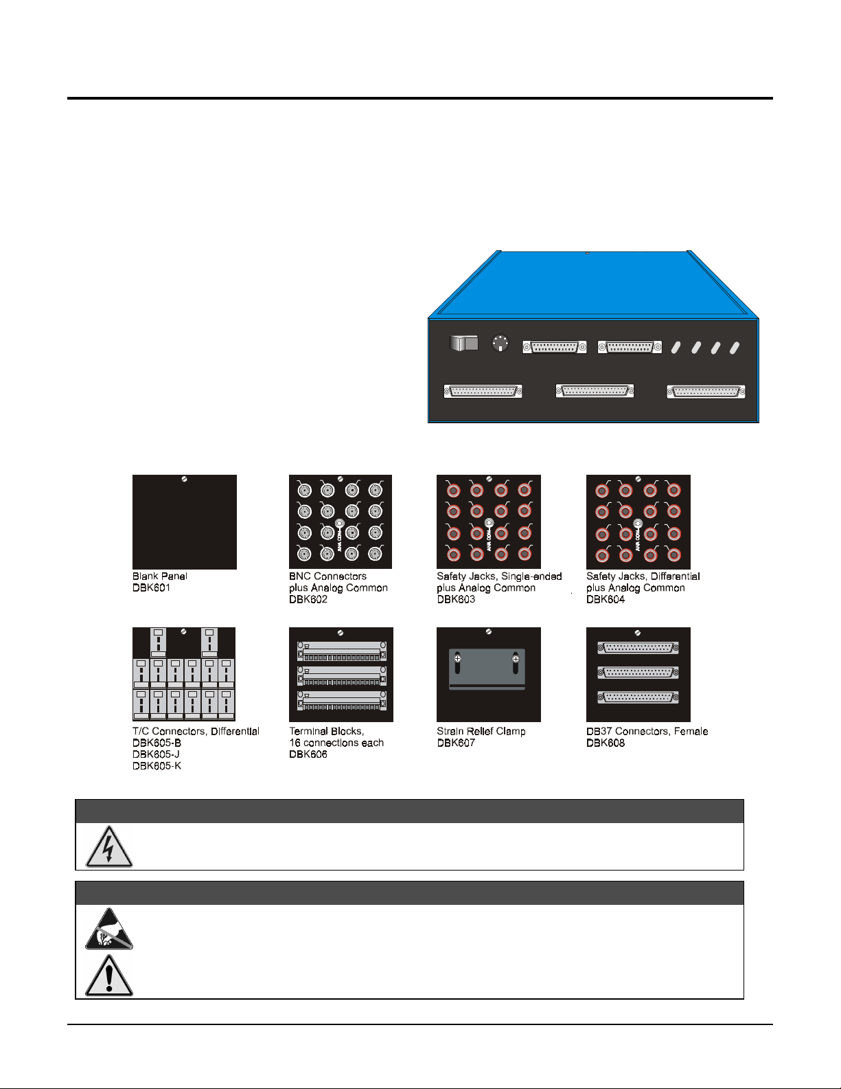
The front panel has male DB37 connectors for
system expansion via P1, P2, and P3. Above the
DB37 connectors, the DaqBook section includes a
power switch, a DIN-5 connector for power-in, a
DB25 connector for printer pass-through, a DB25 to
the PC’s parallel port, and LED status indicators for
power, buffer overload, P1-P2-P3 active, and A/D
active.
POWER
1
0
POWER IN
(+7VDC TO +20VDC)
TO PARALLEL PRINTER
FROM PC PARA LLEL PORT
DaqBook260
POWER BUFFER P1-P2-P3
OVERRU N
ACTIVE ACTIVE
TM
A/D
P1
P2
The rear panel is made of three termination panels with connectors for the various sensors.
++
+
+
+
A
B
C
15 16
CHROM +
ALUMEL -
K
1723182419252026212722
CHROM +
CHROM +
ALUMEL -
ALUMEL -
K
K
CHROM +
CHROM +
ALUMEL -
ALUMEL -
K
K
CHROM +
ALUMEL -
K
CHROM +
CHROM +
CHROM +
ALUMEL -
ALUMEL -
ALUMEL -
K
K
K
CHROM +
CHROM +
CHROM +
ALUMEL -
ALUMEL -
ALUMEL -
K
K
K
DBK605-R
DBK605-S
DBK605-T
1
234
5
678
9
10 11 12
13 14 15
A
CHROM +
ALUMEL -
K
28
CHROM +
ALUMEL -
K
BB
C
16
A
C
1
234
5
678
9
10 11 12
13 14 15
16
-
1
-
34
-
56
-
78
-
2
-
+
-
+
-
+
A
B
C
P3
Electrical Shock Hazard! To avoid injury or equipment damage, turn off power to all connected
equipment during setup.
Use ESD tools, containers, and procedures during setup of DBK cards. Electrostatic discharge can
damage some of the components.
To prevent pin damage, align DBK cards with the backplane DB37 connectors before gently
pressing them together.
p/n 1034-0902, rev. 2.0
WARNING
WARNING
WARNINGWARNING
CAUTION
CAUTION
CAUTIONCAUTION
(Released per EO # 2109R11) Jan. 1999
DaqBook/260 User’s Guide 1
Page 2
Hardware Setup
1 – Turn off system power and disconnect DaqBook/260
If the DaqBook/260 is presently connected in a system, turn off all system devices and disconnect it.
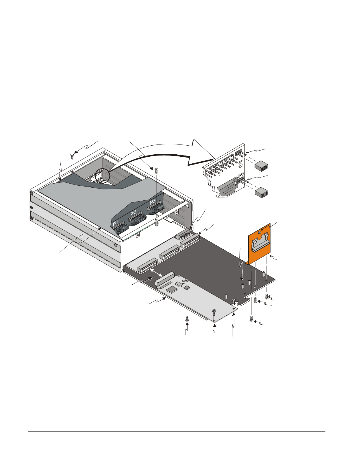
2 – Remove top cover
Remove the two top cover screws and slide off the top cover (see figure). DaqBook jumpers are now accessible.
3 – Remove card drawer
A. Remove the two screws holding the card drawer to the chassis (see figure).
B. Loosen the three captive thumbscrews holding the termination panels to the chassis (see figure).
C. Using the handle, carefully slide out the card drawer.
4 – Remove termination panels
Remove the two screws mounting each termination panel to the card drawer (see figure).
DaqBook/20 0 sits
on a shelf above
the card drawer
Top Cove r
()cut-away view
Top Cover Screws
Step s 2 and 15
DBK Card to
Interconnect Board
Step s 7A and 10A
Card Drawer
P1 Interconnect Board
Card Drawer to Chassis Connector
Internal DB37 connects
to DBK cards. (1 of 3)
Standoff
(2 per card)
JP1 Jumper
Step 6B
JP2 Jumper
Step 6A
Thumbscrew
(1 of 3)
Step s 3B and 13C
Termination Panel
(1 of 3)
Termination Panel to
Card Drawer Screws
Step s 4 and 12
Card Drawer to
Chassis Screw
(1 of 2)
DaqBook/260 Hardware Setup
Card Drawer to
Chassis Screw
(1 of 2)
Step s 3A and 13D
DBK Card to
Card Drawer Screws
Step s 7B and 10B
Step s 3A and 13D
5 – Determine power requirements
Depending on the power needs of your system’s DBK cards, you may need to add a power card. Refer to
Calculating Your Power Needs in chapter 5 of the DaqBook/DaqBoard/Daq PC-Card User’s Manual.
A. Use the
DBK Power Requirements Work Table
to calculate the power requirements of your system’s DBK
cards.
B. Use the
Available Power Chart
to determine your system’s power availability.
C. If the required power in step 5A is more than the available power in step 5B, you need an additional power
card. There are three auxiliary power supply cards:
• DBK32A – For use with a LogBook, DaqBook, or DaqBoard. It supplies ±15 V.
2 DaqBook/260 User's Guide p/n 1034-0902 rev 2.0
Page 3

• DBK33 – For use with a Log Book, DaqBook, DaqBoard, or Daq PC-Card. It supplies +5 V and ±15 V.
y
(-)
gh (+)
y
• CDK10 – For use with a Daq PC-Card. It supplies +5 V and ±15 V. The power source is housed in its
own expansion chassis.
6 – Configure chassis for power sources
Avoid having more than one power source on the P1 bus. +5 V is controlled by the JP1 and JP2 jumpers inside
the chassis. ±15 V is controlled by the JP1 jumpers on the acquisition processor.
A. If +5 V will be supplied to DBK cards outside the chassis, install the JP2 jumper on the P1 interconnect board
(see figure).
B. If +5 V will be supplied to DBK cards inside the chassis, install the JP1 jumper on the P1 interconnect board
(see figure).
C. If using a DBK32A or DBK33 power card anywhere in the system, remove the +15 V/-15 V jumpers from
JP1 on the acquisition processor board. Refer to
Hardware Setup
in the DBK32A or DBK33 section of the
DaqBook/DaqBoard/Daq PC-Card User’s Manual.
7 – Install power card if necessary
If you determined in step 5 that additional power is needed, add a DBK32A or DBK33 power card to the chassis.
(The CDK10 power card is housed in its own chassis.)
A. Carefully align the power card’s DB37 connector with a DB37 connector on the interconnect board and
gently press them together (see figure).
B. Mount the power card with two screws into the standoffs on the card drawer (see figure).
8 – Configure DaqBook/260
Refer to chapter 2 of the DaqBook/DaqBoard/Daq PC-Card User’s Manual. If a DaqBook/260 driver is not
available in software, select DaqBook/200.
9 – Configure DBK cards
10 – Install DBK cards
11 – Connect internal signals
BNC Connecto r
Termination Panel
()internal side
Configure unique channel addresses with the jumpers on the DBK cards. Some cards have other jumpers and/or
DIP switches. Refer to the particular DBK sections of the DaqBook/DaqBoard/Daq PC-Card User’s Manual.
You must use all analog DBK cards in the DaqBook/260. (A factory modification is available to use all digital
cards.)
A. Carefully align the DBK card’s DB37 connector with a DB37 connector on the interconnect board and gently
press them together (see figure).
B. Mount the DBK card with two screws into the standoffs on the card drawer (see figure).
C. Continue installation of any remaining DBK cards.
Connect signal inputs from DBK cards to termination panels. DBK cards connect to the termination panels in
various ways (see figure and particular DBK sections in manual):
•
Single-ended connections use analog common.
•
Differential connections require the proper polarity, typically red-to-red for high (+) and black-to-black for
low (-).
• For thermocouples, red is generally the low side, and the T/C connector and wire type must match the T/C
type used.
Jack Connector
High (+)
+
_
Black
Low (-)
Red
High (+)
Low (-)
Red
T/C Connector
Termination P anel
()external side
Safet
()Single-ended use
Low (-) connects to
analog common
(not shown).
Termination Panel
()internal side
Red
High (+)
Termination Panel
()internal side
Safet
Jack Connectors
()Differential use
Black
Low
Red
Hi
p/n 1034-0902 rev 2.0 DaqBook/260 User's Guide 3
Page 4

12 – Install termination panels
(
g
Mount the termination panels to the card drawer with two screws for each panel (see figure).
13 – Install card drawer
The card drawer slides into the bottom track of the chassis.
A. Hold the card drawer by its handle and tilt it up slightly. Place it on the bottom track of the chassis.
B. Carefully slide the card drawer into the chassis. When it engages the bottom track, level the card drawer and
continue inserting it until it engages with the P1 interconnect board.
C. Tighten the three captive thumbscrews holding the termination panels to the chassis (see figure).
D. Install the two screws holding the card drawer to the chassis (see figure).
14 – Connect external signals
Connect signal inputs from sensors to termination panels.
15 – Install top cover
Slide on the top cover and install the two top cover screws (see figure).
16 – Turn on system power and check operation
DaqBook/260 Function Block Diagram
J1
37
P1
External
DB37
Pins
2-37
Pin 1 (+5V)
JP2
1 of 3 user-supplied
DBK cards
be all analo
digital--no mixing)
all 3 must
or all
Vario us
connector
types are
available.
To
Sensors
J3 connects
to P1 on
DaqBook
internal cable.
PULSE/FREQ.
HIGH-SPEED
DIGITAL I/O
P2
DIGITAL I/O
P3
by
Interconnect
37
P1
JP1
J3
P1
Board
Dual 12-bit DAC
24-bit general purpose
digital I/O lines
Internal DB37
Interconnect Board
4 digital outputs
for high-speed
channel expansion
4 general purpose
digital outputs
4 general purpose
digital inputs
1 auxiliary counter gate
1 TTL trigger input
2 gain select for expansion
16 high-speed
digital inputs
5 counter/timer
channels
(1 of 3)
8 DE/16 SE
analog input
multiplexer
-or-
-or-
PGA
x1, x2
x4, x8
per channel
512-step, random access
channel/gain sequencer
Trigger
Select
Analog Trigger-In
Comparator
DaqBook/260 Block Diagram
Amplifier
Sample
&
Hold
Sequencer
reset
Programmable
sequencer
timebase.
10 us to 10 hrs
+5
+15
-15
DC-DC
converter
Termination
Panels (3)
16-bit, 100 kHz
Analog-to-Digital
Converter
10 kHz
Clock
512 word
FIFO
data
buffer
Fuse
ON/OFF
Switch
DB25P
to PC
parallel
port
DB25S
pass-through
to printer
DIN-5
10-20 VDC
Power In
DaqBook/260 Specifications
Description: DBK Card Expansion chassis accommodating 3 DBK cards, with configurable power capability and a built-in DaqBook/200.
Selection of 7 termination panels to allow custom user input connection.
Capacity: Accommodates any 3 DBK expansion cards; (DaqBook/260 supports only Analog DBK cards in its enclosure, however digital cards
are supported externally via the P2 connector or its connection to a DBK60 enclosure)
4 DaqBook/260 User's Guide p/n 1034-0902 rev 2.0
Page 5

Material and Finish: Aluminum and Steel; black, powder-coated
Dimensions: 280 mm x 330 mm x 89 mm (11” x 13” x 3.5”)
Weight: 3.08 kg empty (7 lbs.); 3.96 kg with built-in DaqBook/200; cards .25 to .75 kg each (8 to 12 oz)
General: Power Consumption (without cards) 620 mA, 0-12 V; Operating Temperature: 0º to 50ºC; Storage Temperature: 0º to 70ºC; Humidity:
0 to 95% RH non-condensing
p/n 1034-0902 rev 2.0 DaqBook/260 User's Guide 5
 Loading...