

Page 1

DaqBook/2000 Series
Installation Guide
For DaqBook/2000A, /2000E, /2000X
the smart approach to instrumentation ™
IOtech, Inc.
25971 Cannon Road
Cleveland, OH 44146-1833
Phone: (440) 439-4091
Fax: (440) 439-4093
E-mail (Product Information): sales@iotech.com
E-mail (Technical Support): productsupport@iotech.com
Internet: www.iotech.com
DaqBook/2000 Series
Installation Guide
16-Bit, 200 kHz Multifunction
Data Acquisition Systems
p/n
1103-0940
Rev.
2.0
1103-0940, rev 2.0
968596
DaqBook/2000 Series Installation Guide IG-1
Page 2

IG-2 DaqBook/2000 Series Installation Guide
968596
1103-0940, rev 2.0
Page 3
Contents
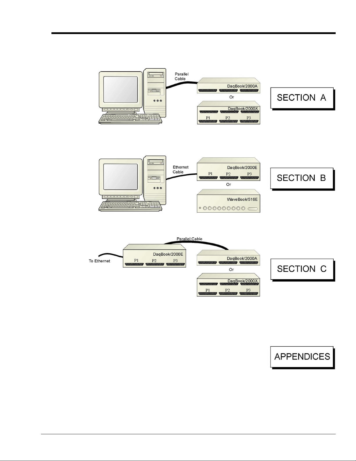
A Comparison of Device Features …… IG-4
Connecting a DaqBook/2000A or DaqBook/2000X to a PC Parallel Port [Section A]
Connecting a DaqBook/2000E, or WaveBook/516E to the Ethernet [Section B]
Connecting a DaqBook/2000A or DaqBook/2000X to a DaqBook/2000E [Section C]
Appendix D – Device Connector Reference
Appendix E – System Expansion
Appendix F – Adding a Parallel Port to the PC
Appendix G – Resource and Performance Tests
1103-0940, rev 2.0
968596
DaqBook/2000 Series Installation Guide IG-3
Page 4
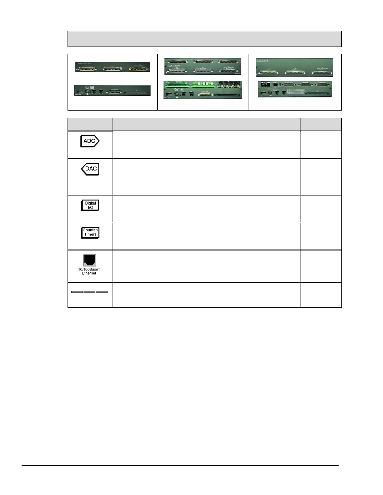
A Comparison of Device Features
DaqBook/2000A
DaqBook/2000X
DaqBook/2000E
Feature Description Applies to:
16
4
(with DBK46)
40
6
3 Card Exp.
Analog Input Channels
Analog Input signals enter through P1 and/or P4, go to MUX, to PGA, to Gain
& Offset Amplifier, then to Analog-to-Digital Converter (ADC).
Analog Output Channels [Available only with DBK46 Option]
Digital Signals go through Digital-to-Analog Converters via the optional
DBK46 plug-in card, then through “DAC Out” on P3 and P4. The card
includes a 256K Sample Buffer. Note that the DBK46 option is a “Factory
Install” Option Only.
Digital I/O Channels
Digital signals pass through one 16-bit Digital I/O Port and three 8-bit Digital
I/O Ports located on P2, P3, and/or P4.
Counter/Timers
Four 16-bit Counter Input signals and Two 16-bit Timer Output signals via P3
and/or P4 and System Controller.
10/100BaseT Ethernet Interface located on the chassis
DaqBook/2000E includes a 10/100BaseT Ethernet interface.
The
Note that DaqBook/2000A and DaqBook/2000X can connect to the
DaqBook/2000E, or to a WBK25 Ethernet module.
3 Card Expansion
DaqBook/2000X includes three expansion slots that can accept a
The
wide variety of analog and digital DBK signal conditioning cards.
All Models
Each model,
providing a
DBK46 is
installed.
All Models
All Models
/2000E
/2000X
DaqBook/2000 Series Devices are high-speed, multi-function, data acquisition systems for use with
notebook and desktop PCs. They feature a 16-bit, 200-kHz A/D converter, digital calibration, 40 digital
I/O lines, four counters, and two timers and
, if the optional DBK46 card is installed
, four 16-bit, 100-kHz
D/A converters
Up to 470 channels of analog and digital I/O can be accessed with one DaqBook/2000 Series Device.
All input and output signals can be connected via the three 37-pin DSUB connectors [P1, P2, and P3]
located on the front panel. Duplicate I/O connectivity is also available on the rear panel via the 100-pin, P4
connector.
• P1 – Analog input port for 16 single-ended or 8 differential analog inputs with 13 software
programmable ranges (±10 V to ±156 mV full scale).
• P2 – General purpose digital I/O port with 24 lines, or digital I/O expansion port controlling
up to 192 external lines.
• P3 – 16-bit digital I/O port, counter inputs, timer outputs, and analog outputs.
• P4 – this 100-pin connector allows for optional connection to a DBK200 Series Device for
expansion from the rear panel. P4 connectivity provides no additional I/O to that which is
available to P1, P2, and P3.
IG-4 DaqBook/2000 Series Installation Guide
968596
1103-0940, rev 2.0
Page 5
Section A
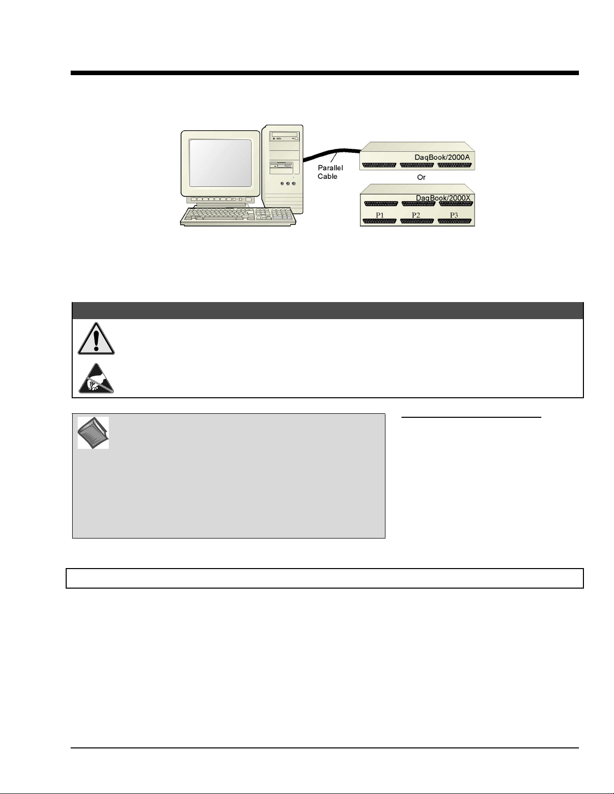
Connecting a DaqBook/2000A or a DaqBook/2000X to a PC Parallel Port
Connecting a DaqBook/2000A or a DaqBook/2000X to a PC Parallel Port
CAUTION
CAUTION
CAUTIONCAUTION
Turn off power to the system devices and externally connected equipment before connecting cables.
Electric shock or damage to equipment can result even under low-voltage conditions.
Take ESD precautions (packaging, proper handling, grounded wrist strap, etc.)
.
Reference Note: Adobe PDF versions of user manuals will
automatically install onto your hard drive as a part of product
support. The default location is in the Programs group, which
can be accessed from the Windows Desktop. You can also
access documents directly from the data acquisition CD via the
<View PDFs> button located on the CD’s opening screen.
Refer to the PDF documentation for details regarding both
hardware and software. Note that hardcopy versions of the
manuals can be ordered from the factory.
STEP A.1 –
1.
Remove
Programs feature.
2. Place the Data Acquisition CD into the CD-ROM drive. Wait for PC to auto-run the CD. This may take a
few moments, depending on your PC. If the CD does not auto-run, use the Desktop’s Start/Run/Browse
feature to locate and run the CD’s setup.exe file.
Minimum System Requirements
PC system with Pentium® Processor
Windows Operating System
RAM, as follows:
32 Mbytes of RAM for Windows 95/98/NT
64 Mbytes of RAM for Windows Me
64 Mbytes of RAM for Windows 2000
64 Mbytes of RAM for Windows XP
Install the Software
previous version Daq drivers, if present. You can do this through the Windows Add/Remove
3. After the intro-screen appears, follow the screen prompts.
Section A
969696
Connecting a DaqBook/2000A or /2000X to a PC Parallel Port A-1
Page 6
STEP A.2 –
Connect the DaqBook/2000A or DaqBook/2000X to a Parallel Port
What you will need
• A computer with an available parallel port. If your PC has no parallel port available, refer to
Appendix F, Adding a Parallel Port to the PC.
• One parallel port cable, e.g. a CA-35-2 (2-foot) or a CA-35-12 (1-foot) cable.
How to make the connection:
1. Connect the parallel port cable to the parallel port connector on the rear panel of the
DaqBook/2000A or DaqBook/2000X.
2. Connect the other end of the cable to the parallel port connector on the PC.
:
DB25 Parallel Port Connector
STEP A.3 –
Connect the System to Power
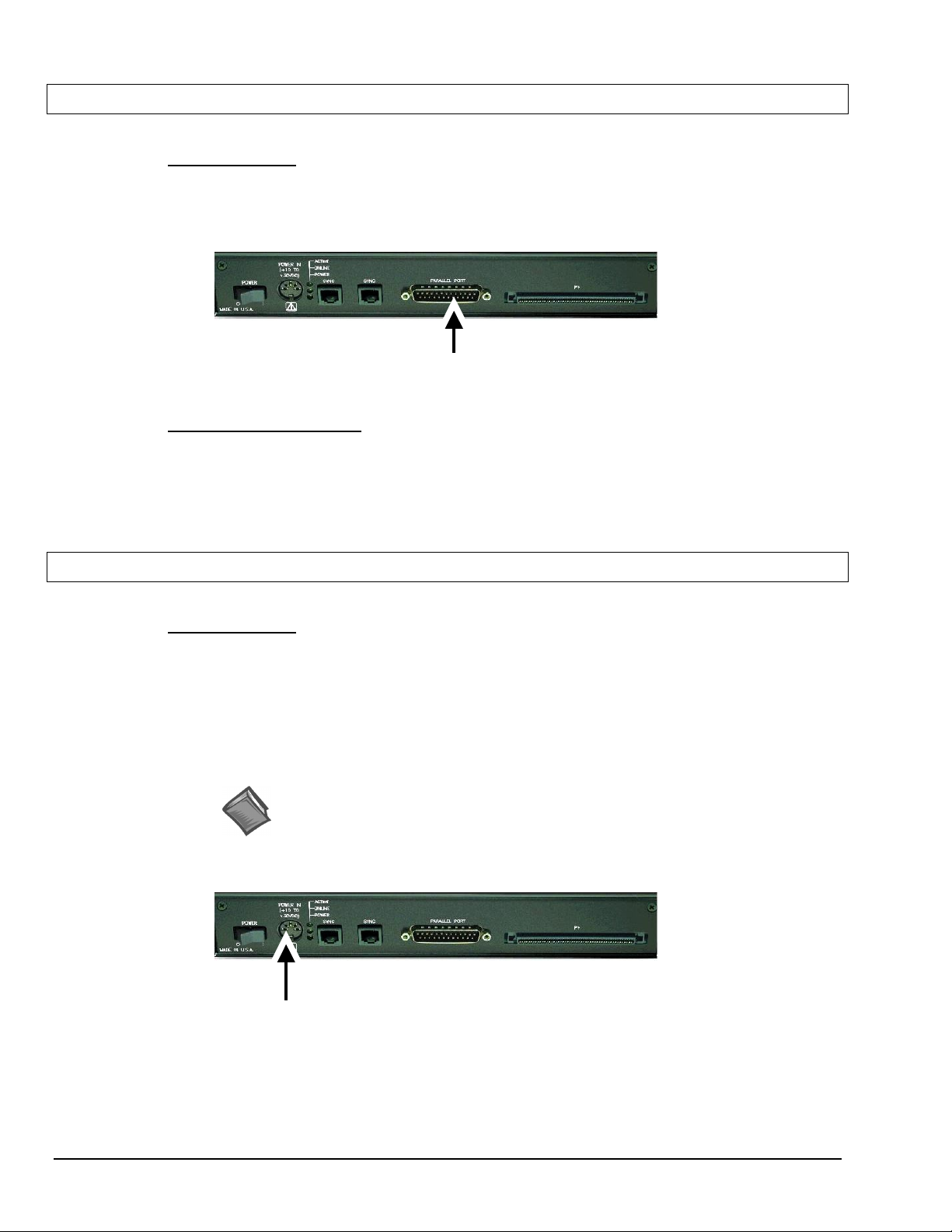
What you will need
A power supply with a range of +10 VDC to +30 VDC.
The power supply needs to have a male DIN5 connector.
Note: The switching-mode power supply that is commonly used with DaqBook/2000 Series systems
Note: Various AC adapter models support power grids of USA, Europe, Japan, and Asia.
DIN5 POWER IN Connector (+10 to +30 VDC)
:
has an input range of 100 VAC to 240 VAC at 50 Hz to 60 Hz. The power supply’s output
[to the DaqBook/2000 Series device] is 15 VDC @ 2.7 amps via a DIN5 connector.
Reference Note: It is possible to use a VDC power source other than the commonly
used switching-mode power supply, often referred to as an adapter. However, you
should consult the Power Management Section of your DaqBook/2000 Series User’s
Manual (p/n 1103-0901) before doing so.
A-2 Connecting a DaqBook/2000A or /2000X to a PC Parallel Port
969696
Section A
Page 7
How to make the connection:
1. Place the DaqBook/2000 Series device power switch in the “OFF” (0) position, if it is not
already OFF.
2. Connect the DIN5 end of the adapter’s cable to the power in connector on the DaqBook/2000
Series device (see the preceding figure).
If using a power source other than the adapter, consult the Power Management Section of your
DaqBook/2000 Series User’s Manual (p/n 1103-0901) before doing so.
3. Connect the adapter’s plug to a standard AC outlet.
4. If your adapter has a power switch, position it to “ON.”
5.
urn ON the DaqBook/2000 Series device’s power by placing the power switch to the “1”
T
position. The power led will light up.
STEP A.4 –
Configure and Test the Hardware
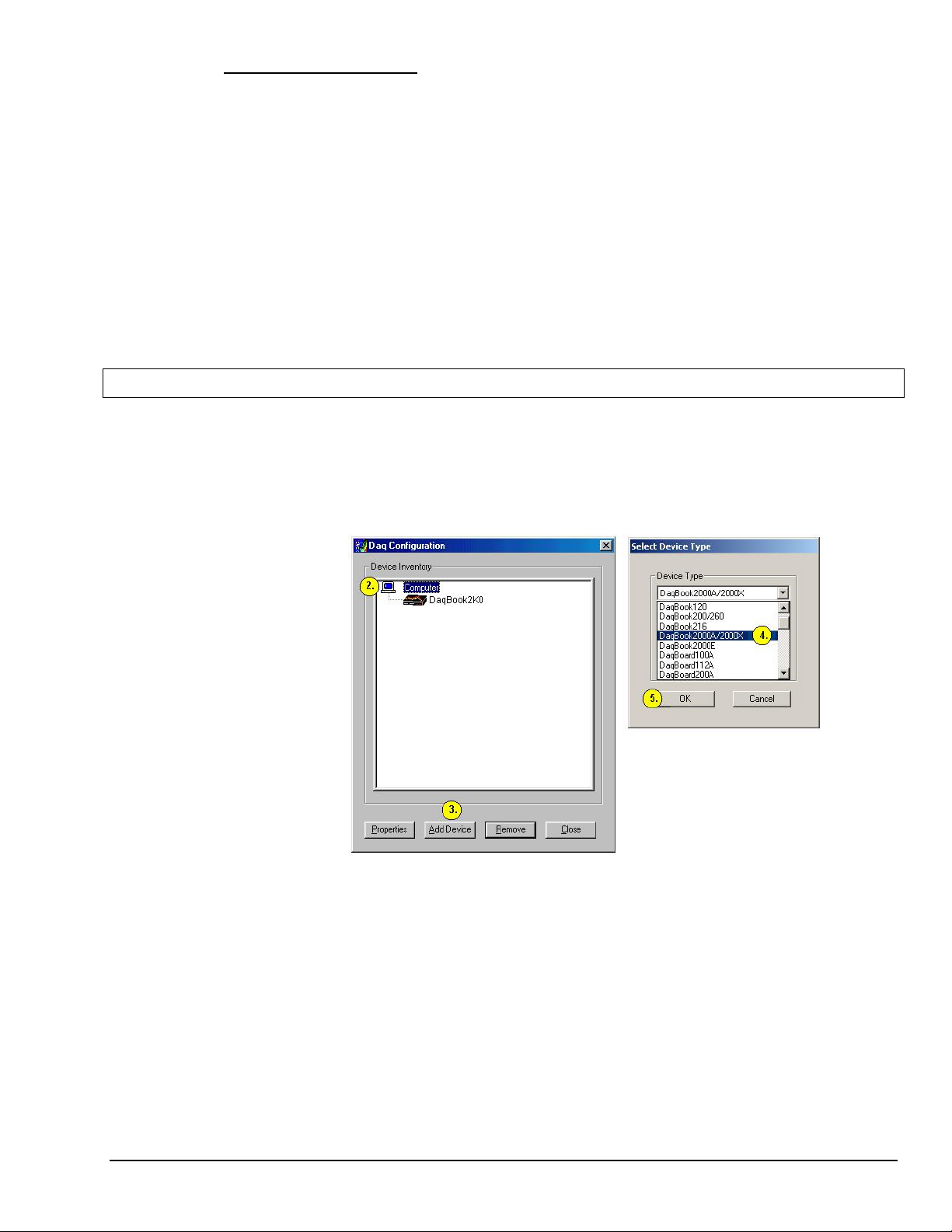
1. Run the Daq*Configuration control panel applet. The applet can be accessed by navigating
from the Windows’ Desktop as follows:
Start ⇒⇒⇒⇒ Settings ⇒⇒⇒⇒ Control Panel ⇒⇒⇒⇒ Daq* Configuration
2. Select the “Computer” image in the Device Inventory configuration tree (see figure).
3. Click the <Add Device> button. The “Select Device Type” box will appear.
Section A
4. Select “DaqBook2000A/2000X” from the “Device Type” scroll-down.
Note that the default name that appears in the Device Inventory configuration tree, e.g.,
“DaqBook2K0” can be renamed.
5. Click the <OK> button. The “Properties” box will appear for the selected device.
6. Ensure settings are correct, and make changes if needed. Refer to the following table for
throughput speeds.
969696
Connecting a DaqBook/2000A or /2000X to a PC Parallel Port A-3
Page 8
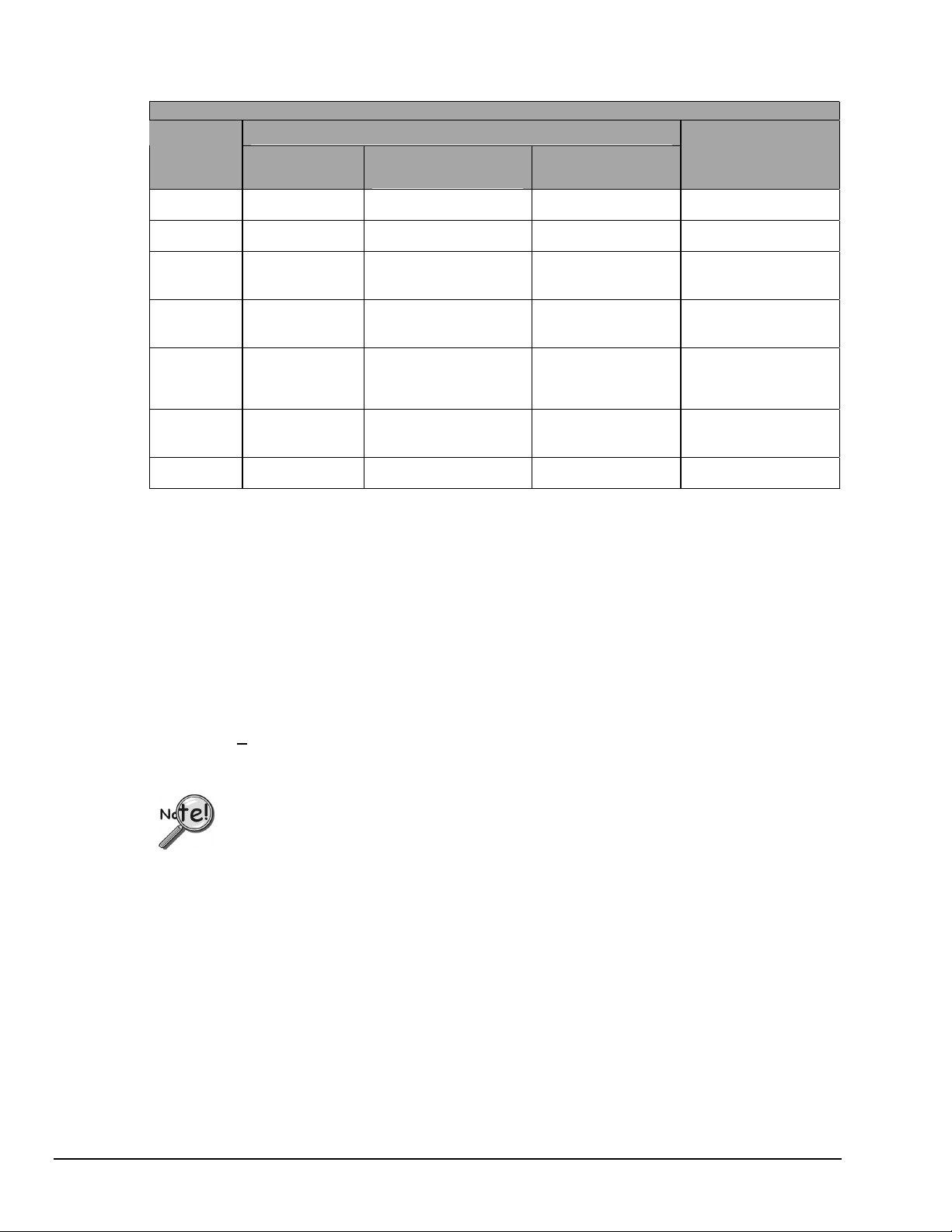
Support for Parallel Port Communication Protocols
Protocol
Device Type, Applicability to
WaveBooks DaqBook/2000
Series
LogBooks
Estimated
Throughput
(Note 2)
4 bit Yes Yes No 40 to 50 Ks/sec
8 bit Yes Yes No 80 to 100 Ks/sec
SMC666
Yes Yes No 350 to 370 Ks/sec
EPP
Fast EPP
Yes Yes
No 500 Ks/sec
(Note 1)
(WBK20)
Fast EPP
(WBK21)
Fast EPP
Yes Yes No 1.2 / Ms/sec
Yes Yes No 500 Ks/sec
(WBK23)
ECP Yes Yes Yes 350 to 400 Ks/sec
Note 1: No Windows NT support.
Note 2: The values of expected throughput are estimates only. Actual thru-put may vary due to the specific
parallel port capabilities and BIOS settings of the computer involved.
7. Select the “Test Hardware” tab.
8. Verify that the DaqBook/2000 Series device has been properly installed and powered-on. Proper
installation includes the parallel port cable being firmly in place on both the DaqBook/2000 Series device
and on the host PC’s parallel port.
9. Click the <Resource Test> button.
Appendix G, Resource and Performance Test, includes a brief explanation of the test.
10. Click the <T
est> button.
Testing the DaqBook/2000 Series device may, in some cases, cause the system to hang.
If test results are not displayed in 30 seconds or the system does not seem to be responding,
reboot the system. Upon power-up, re-enter the Daq Configuration and change the
DaqBook/2000 Series device configuration settings to those that work properly.
This completes the instructions for connecting a DaqBook/2000A or a DaqBook/2000X to a PC parallel port.
At this point you should refer to the DaqBook/2000 Series User’s Manual (p/n 1103-0901) for additional
system information. You can access the document directly from the opening screen of the data acquisition CD
via the <View PDFs> button. The user manual includes pinouts, information on system expansion, data
acquisition, and links to software and programming documents (in PDF format).
A-4 Connecting a DaqBook/2000A or /2000X to a PC Parallel Port
969696
Section A
Page 9
Section B
Connecting a DaqBook/2000E or WaveBook/516E to the Ethernet
Connecting a DaqBook/2000E or WaveBook/516E to the Ethernet
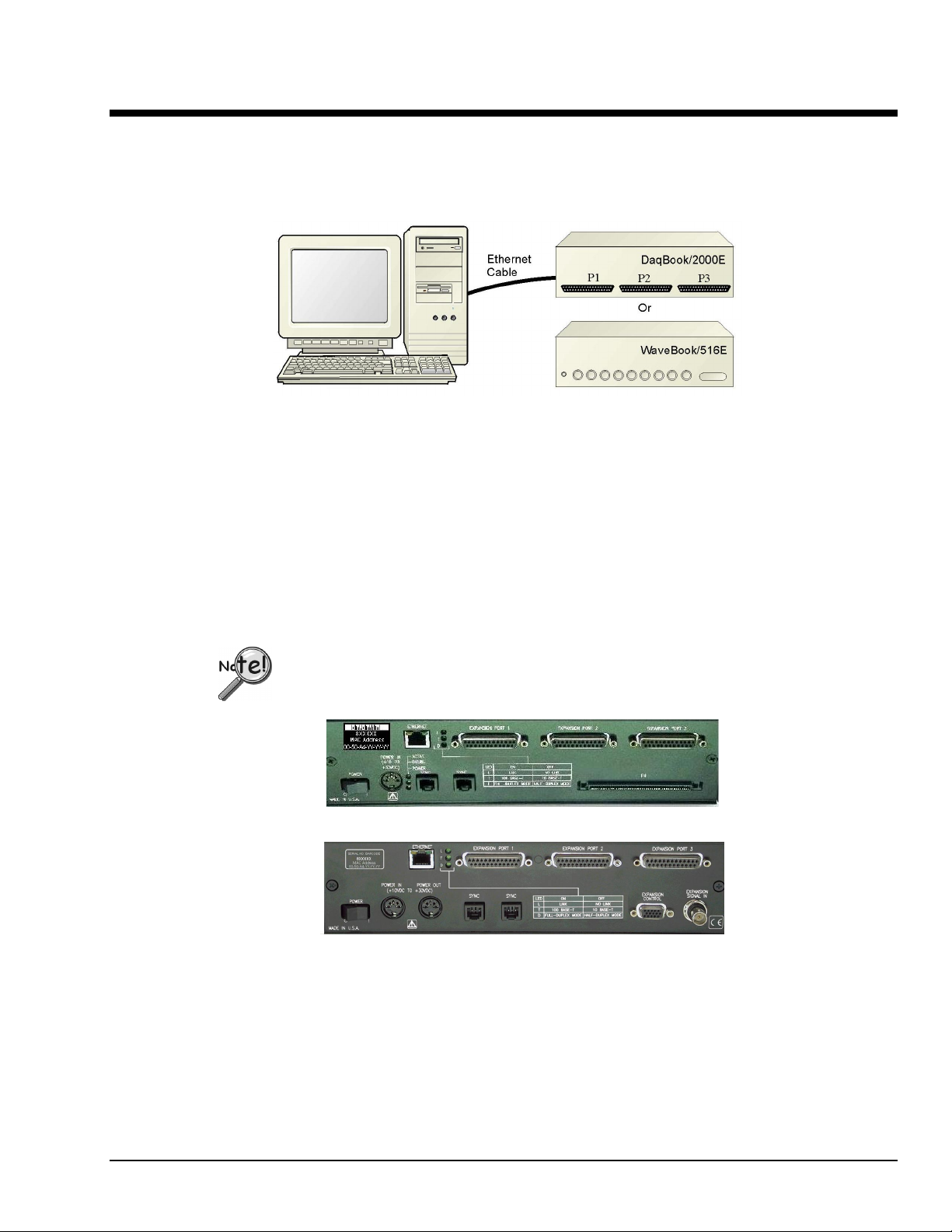
Introduction
The DaqBook/2000E and WaveBook/516E connect directly to an Ethernet port on a PC or network hub via
the their built-in 10/100BaseT Ethernet interface. An Ethernet patch cable CA-242 (1.5 foot) or CA-242-7
(7 foot) cable is used to make the connection.
Contact the factory or your service representative in regard to Ethernet connectivity if
your operating system is other than Windows NT, Windows 2000, or Windows XP.
The DaqBook/2000E and WaveBook/516E can be used as Ethernet interface devices for sister
products that are not capable of direct Ethernet connection.
DaqBook/2000E
WaveBook/516E
Section B
969596
Connecting a DaqBook/2000E or WaveBook/516E to the Ethernet B-1
Page 10
CAUTION
CAUTION
CAUTIONCAUTION
Turn off power to the system devices and externally connected equipment before connecting cables.
Electric shock or damage to equipment can result even under low-voltage conditions.
Take ESD precautions (packaging, proper handling, grounded wrist strap, etc.)
Reference Note: Adobe PDF versions of user manuals will
automatically install onto your hard drive as a part of product
support. The default location is in the Programs group, which
can be accessed from the Windows Desktop. You can also
access documents directly from the data acquisition CD via the
<View PDFs> button located on the CD’s opening screen.
Refer to the PDF documentation for details regarding both
hardware and software. Note that hardcopy versions of the
manuals can be ordered from the factory.
STEP B.1 –
1.
Remove
Programs feature.
2. Place the Data Acquisition CD into the CD-ROM drive. Wait for PC to auto-run the CD. This may take a
few moments, depending on your PC. If the CD does not auto-run, use the Desktop’s Start/Run/Browse
feature.
3. After the intro-screen appears, follow the screen prompts.
Minimum System Requirements
PC system with Pentium® Processor
Windows Operating System
RAM, as follows:
32 Mbytes of RAM for Windows 95/98/NT
64 Mbytes of RAM for Windows Me
64 Mbytes of RAM for Windows 2000
64 Mbytes of RAM for Windows XP
Install the Software
previous version Daq drivers, if present. You can do this through Microsoft’s Add/Remove
STEP B.2 –
B-2 Connecting a DaqBook/2000E or W aveBook/516E to the Ethernet
Determine the type of Network Connection
To properly connect and configure a DaqBook/2000E or a WaveBook/516E, you must determine the type
of network that the device will become part of. This is because the type of network used has a direct
bearing on the IP address of the device.
Briefly, the four network types are as follows:
• Dedicated Network - with a direct cable connection from the PC to the device
• Dedicated Network - making use of a network hub or switch
• LAN with a DHCP Server
(Local Area Network with a Dynamic Host Configuration Protocol)
• LAN with no DHCP Server
(Local Area Network with no Dynamic Host Configuration Protocol)
Brief descriptions and illustrations follow.
969596
Section B
Page 11
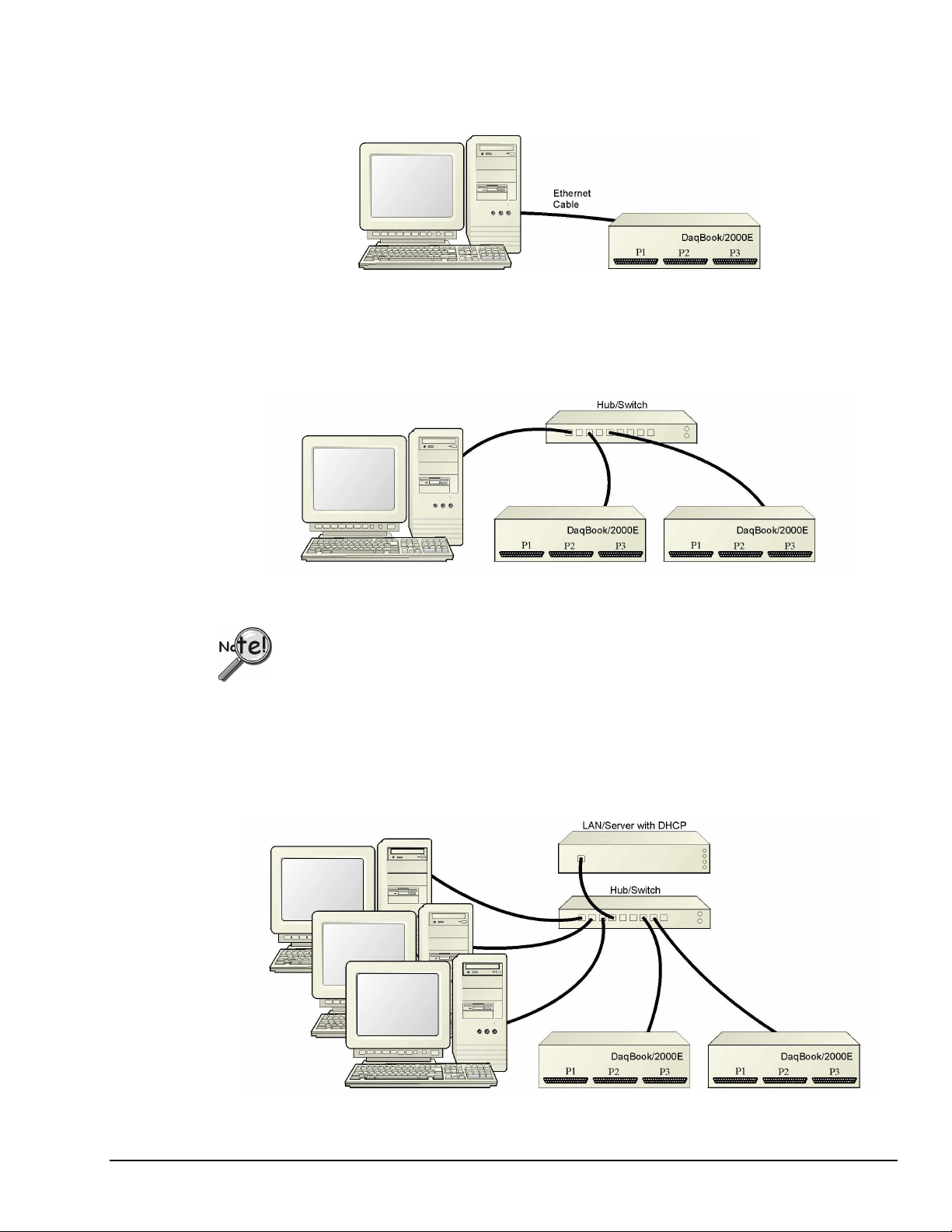
Dedicated Network - with a direct cable connection from the PC to the device
In this scenario a DaqBook/2000E or a WaveBook/516E is connected directly to an Ethernet jack on a host
computer.
Dedicated Network using a Direct Cable Connection
Dedicated Network - making use of a network hub or switch
In this scenario the DaqBook/2000E or WaveBook/516E connects to the Ethernet through a network hub or
switch. At least one computer is also connected to the hub.
Dedicated Network using a Hub/Switch
Some network devices such as a wireless access point may act as a DHCP server. If this is
the case, follow the instructions for the LAN with DHCP server. For detailed information
consult the documentation that is specific to your network device.
LAN with a DHCP Server (Local Area Network with a Dynamic Host Configuration Protocol)
Many corporations use the LAN/Server with DHCP arrangement for their networks. In this type of setup
several computers are typically connected to a network that makes use of a DHCP server. In addition, a
DaqBook/2000E or WaveBook/516E is connected to the network hub/switch.
Section B
969596
LAN with a DHCP Server
Connecting a DaqBook/2000E or WaveBook/516E to the Ethernet B-3
Page 12

Notes:
Using a DaqBook/2000E or WaveBook/516E on a typical LAN may affect the speed of the network
and internet data transfer. Because of this we recommend adding a network card to the computer
and using one of the two dedicated network configurations.
Contact your network administrator before connecting a DaqBook/2000E or a WaveBook/516E
to a corporate network.
LAN with no DHCP Server [Currently Not Supported]
(Local Area Network with no Dynamic Host Configuration Protocol)
This scenario looks the same as that shown in the previous illustration, except there is no Dynamic Host
Configuration Protocol (DHCP). In this type of setup, one or more computers are connected to a network;
and each computer has a static IP address. This configuration is currently not supported. We recommend
adding a network card to the computer and using one of the two dedicated network configurations.
STEP B.3 –
Connect the System Components
Reference Note:
For examples of system connections, including cable use, refer to the following documents, as applicable:
For DaqBook/2000 Series systems refer to Appendix E - System Expansion in the installation
guide (p/n 1103-0940).
For WaveBook systems refer to the System Enhancement and Expansion section of the WaveBook
User’s Manual (p/n 489-0901).
What you will need to connect a DaqBook/2000E or a WaveBook/516E to the Ethernet
• An available connection to the Ethernet. The connection can be either
- an Ethernet jack on a computer or
- an Ethernet jack on a hub that is connected to the Ethernet.
• An Ethernet patch cable, e.g., a CA-242 (1.5 foot cable) or a CA-242-7 (7-foot cable).
1. Connect the Ethernet cable to the Ethernet jack on the DaqBook/2000E or WaveBook/516E.
2. Connect the other end of the Ethernet cable to the Ethernet jack on the host computer or
network hub.
:
B-4 Connecting a DaqBook/2000E or W aveBook/516E to the Ethernet
969596
Section B
Page 13

STEP B.4 –
Power-up the System Components
What you will need
• A power supply with a range of +10 VDC to +30 VDC.
The power supply needs to have a male DIN5 connector.
Note: The switching-mode power supply that is commonly used with these systems has an input
Note: Various AC adapter models support power grids of USA, Europe, Japan, and Asia.
How to make the connection:
1. Using the unit’s power switch, turn the DaqBook/2000E or WaveBook/516E “OFF.
The switch will be in the “0” position and the power LED will be unlit.
2. Connect the DIN5 end of the adapter’s cable to the power in connector on the DaqBook/2000E
or WaveBook/516E.
:
range of 100 VAC to 240 VAC at 50 Hz to 60 Hz. The power supply’s output [to the
device] is typically 15 VDC @ 2.7 amps via a DIN5 connector.
Reference Note: It is possible to use a VDC power source other than the commonly
used switching-mode power supply, often referred to as an adapter. However, you
should consult the Power Management Section of your DaqBook/2000 Series User’s
Manual (p/n 1103-0901) before doing so.
If using a power source other than the adapter, consult the Power Management Section of your
user’s manual prior to doing so.
3. Connect the adapter’s plug to a standard AC outlet.
4. If your adapter has a power switch, position it to “ON.”
5.
urn ON the DaqBook/2000E or the WaveBook/516E by placing the power switch to the
T
“1” position. The power led will light up.
Reference Note:
The power management and power requirements sections of the associated user’s manual should
be reviewed prior to powering up a system.
For DaqBook/2000 Series systems refer the DaqBook/2000 Series User’s Manual
(p/n 1103-0901).
For WaveBook systems refer to the WaveBook User’s Manual (p/n 489-0901).
The PDF versions of these documents can be accessed from the data acquisition CD via the
<View PDFs> button on the CD’s opening screen.
Section B
969596
Connecting a DaqBook/2000E or WaveBook/516E to the Ethernet B-5
Page 14
STEP B.5 -
Configure the Computer’s Network Settings
[Applies to “dedicated networks” only]
If using a LAN (Local Area Network), skip this section and continue with
Configure and Test the System using the Daq*Configuration Applet (page B-9).
1. Open the Control Panel by navigating from the Windows Desktop as follows:
Start Menu ⇒⇒⇒⇒ Settings ⇒⇒⇒⇒ Control Panel.
2. Double-click the “Network and Dial-up Connections” icon.
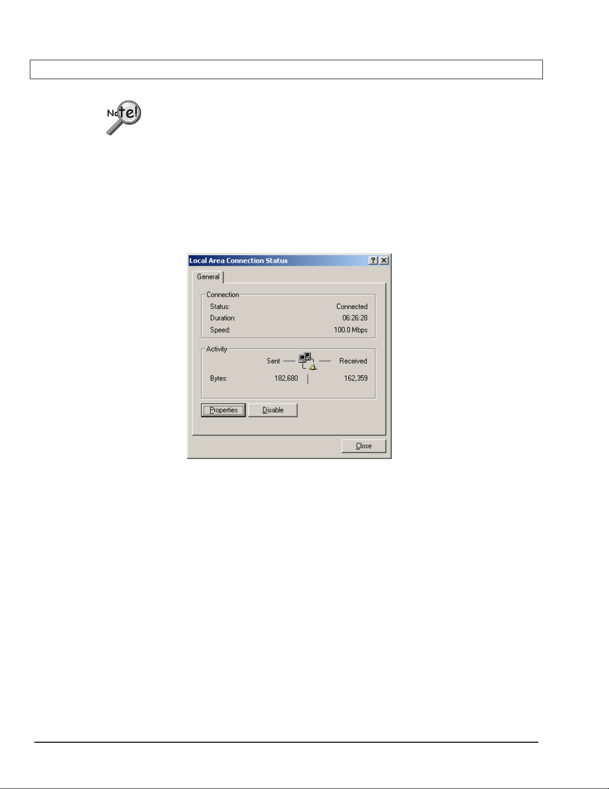
3. Double-click the “Network Connection” icon for the network that the DaqBook/2000E or the
WaveBook/516E is connected to.
Local Area Connection Status
4. In the “Local Area Connection Status” box (previous figure), click on the <Properties> button.
The “Local Area Connection Properties” box will appear (following figure).
B-6 Connecting a DaqBook/2000E or W aveBook/516E to the Ethernet
969596
Section B
Page 15

Local Area Connection Properties
5. Double-click the “Internet Protocol (TCP/IP)” component (previous figure).
The “Internet Protocol (TCP/IP) Properties” box will appear (following figure).
Section B
Internet Protocol (TCP/IP) Properties
969596
Connecting a DaqBook/2000E or WaveBook/516E to the Ethernet B-7
Page 16

Configure the Computer’s TCP/IP settings as follows.
Internet Protocol (TCP/IP) Properties
6. Select the “Use the following IP Address” radio button.
7. Set the IP address field to 10.0.0.x where x is some number from 1 to 255.
Make sure that each computer on the dedicated network has a unique IP address.
8. Set the Subnet mask to 255.0.0.0. Note that the remaining fields can be left unchanged.
B-8 Connecting a DaqBook/2000E or W aveBook/516E to the Ethernet
969596
Section B
Page 17

STEP B.6 -
1. Open the Daq* Configuration Applet.
2. Add the first-level device to the list of installed devices.
Configure and test the System using the Daq* Configuration Applet
The Daq* Configuration applet, designed for 32-bit Windows 95/98/Me/NT/2000/XP systems, is located in
the Windows Control Panel. It allows you to add or remove a device and change configuration settings.
The included test utility provides feedback on the validity of current configuration settings, as well as
performance summaries.
a. Open the Control Panel by navigating from the Windows’ Desktop as follows:
Start Menu ⇒⇒⇒⇒ Settings ⇒⇒⇒⇒ Control Panel
b. From the Control Panel, double-click the Daq* Configuration icon.
The first-level device is the device that will be connected directly to the Ethernet, via a host computer’s
Ethernet jack or a jack on a network hub. The DaqBook/2000E and WaveBook/516E are each examples of
first-level devices.
a. Select the Computer image in the Device Inventory configuration tree (following figure).
b. Click the <Add Device> button. The “Select Device Type” box will appear.
c. Select the DaqBook2000E or the WaveBook516E from the list of devices, as applicable.
d. Click the <OK> button. The “Properties” box will appear for the selected device.
Using Daq* Configuration Device Inventory & Select Device Type to Add a Device
Note: Although the above figure indicates that a WaveBook/516E was selected as the first level
device, we could similarly have a DaqBook/2000E as the first-level device.
Section B
969596
Connecting a DaqBook/2000E or WaveBook/516E to the Ethernet B-9
Page 18

3. Set the properties of the first-level device.
In this step you will set the device properties according to one of the following two methods, depending on
whether you have a “Dedicated Network” or a “LAN with DHCP Server Network.” Illustrations of the
network types are provided on page B-3.
Users of Dedicated Networks
See following figure, left-hand image.
a. In the “Properties” box, enter the serial number of the first-level device (DaqBook/2000E, or
WaveBook/516E).
b. Select the Auto IP Setting Radio button. Note that the IP address of the DaqBook/2000E, or
the WaveBook/516E will automatically be calculated and displayed in the IP Address field.
, follow these 2 steps.
For DEDICATED Networks
For LAN with DHCP Server Networks
Daq* Configuration, Properties Dialog Boxes
Note: Although the above images are based on WaveBook/516E, we could similarly have a
DaqBook/2000E selected in the Properties Dialog Box.
Users of LAN with DHCP Server Networks
See preceding figure, right-hand image.
, follow these 4 steps.
a. Enter the base 10 version of the serial number of the DaqBook/2000E or WaveBook/516E,
as applicable. The number is located on the MAC label. The label is located on the left edge
of the rear panel.
b. Get the IP address of the device from your network administrator. The network administrator
will need the unit powered-on and connected to the network. The administrator will also need
the MAC address label’s hexadecimal number (the label’s bottom number).
c. Select the “Manual IP Setting” radio button.
d. In the IP Address field, enter the IP address obtained from your network administrator.
B-10 Connecting a DaqBook/2000E or W aveBook/516E to the Ethernet
969596
Section B
Page 19

4. Test the system connections.
a. Make sure the device has been properly installed and is powered-on.
b. Make sure all cables are properly and securely connected.
c. Click the “Test Hardware” tab.
d. Click the <Resource Test> button.
The test results have two components: Resource Tests and Performance Tests.
Appendix G, Resource and Performance Tests, includes a brief explanation of the tests.
When testing a WaveBook or DaqBook device, if the unit does not respond within 30
seconds perform the following steps:
1) reboot the system
2) upon power-up, re-open the Daq* Configuration applet
3) select another configuration setting
4) reinitiate the test
This completes the procedure for connecting a DaqBook/2000E or WaveBook/516E to the Ethernet. At this
point you should refer to the more detailed user documentation that applies to your Ethernet-connected
device. User’s manuals typically include pinouts, information on system explanation, data acquisition, and
links to software and programming documents (in PDF format).
Reference Notes:
For additional device and system information:
➣ DaqBook/2000E users should refer to the DaqBook/2000 Series User’s Manual
(p/n 1103-0901) and the DBK Options Manual (p/n 457-0905).
➣ WaveBook/516E users should refer to both the WaveBook User’s Manual,
(p/n 489-0901) and the WBK Options Manual (p/n 489-0902).
➣ Programming information is contained in the Programmer’s Manual, (p/n 1008-0901).
Note: You can access PDF documents directly from the opening screen of the data acquisition CD
via the <View PDFs> button.
Section B
969596
Connecting a DaqBook/2000E or WaveBook/516E to the Ethernet B-11
Page 20

B-12 Connecting a DaqBook/2000E or W aveBook/516E to the Ethernet
969596
Section B
Page 21

Section C
Connecting a DaqBook/2000A or DaqBook/2000X to a DaqBook/2000E
Connecting a DaqBook/2000A or a DaqBook/2000X
to a DaqBook/2000E
CAUTION
CAUTION
CAUTIONCAUTION
Turn off power to the system devices and externally connected equipment before connecting cables.
Electric shock or damage to equipment can result even under low-voltage conditions.
Take ESD precautions (packaging, proper handling, grounded wrist strap, etc.)
Minimum System Requirements
Reference Note: Adobe PDF versions of user manuals will
automatically install onto your hard drive as a part of product
support. The default location is in the Programs group, which
can be accessed from the Windows Desktop. You can also
access documents directly from the data acquisition CD via the
<View PDFs> button located on the CD’s opening screen.
PC system with Pentium® Processor
Windows Operating System
RAM, as follows:
32 Mbytes of RAM for Windows 95/98/NT
64 Mbytes of RAM for Windows Me
64 Mbytes of RAM for Windows 2000
64 Mbytes of RAM for Windows XP
Refer to the PDF documentation for details regarding both
hardware and software. Note that hardcopy versions of the
manuals can be ordered from the factory.
In this section we are dealing with a setup in which: (1) the DaqBook/2000E is already connected to the
Ethernet, and (2) the associated software from the data acquisition CD is installed.
Section C
968596
Connecting a DaqBook/2000A or /2000X to a DaqBook/2000E C-1
Page 22

STEP C.1 –
Connect the DaqBook/2000A or DaqBook/2000X to an Expansion Port on
the DaqBook/2000E
What you will need
One parallel port cable, e.g. a CA-35-2 (2-foot) or a CA-35-12 (1-foot) cable.
How to make the connection:
1. Place the DaqBook/2000E power switch in the “OFF” (0) position, if it is not already OFF.
2. Connect the parallel port cable to the parallel port connector on the rear panel of the
DaqBook/2000A or DaqBook/2000X. See the preceding picture.
3.
Connect the other end of the cable to one of three expansion ports on the DaqBook/2000E.
:
DB25 Parallel Port Connector
Expansion Ports
STEP C.2 –
DaqBook/2000E
Connect the DaqBook/2000A or DaqBook/2000X to Power
What you will need
A power supply with a range of +10 VDC to +30 VDC.
The power supply needs to have a male DIN5 connector.
Note: The switching-mode power supply that is commonly used with DaqBook/2000 Series systems
Note: Various AC adapter models support power grids of USA, Europe, Japan, and Asia.
:
has an input range of 100 VAC to 240 VAC at 50 Hz to 60 Hz. The power supply’s output
[to the DaqBook/2000 Series device] is 15 VDC @ 2.7 amps via a DIN5 connector.
Reference Note: It is possible to use a VDC power source other than the commonly
used switching-mode power supply, often referred to as an adapter. However, you
should consult the Power Management Section of your DaqBook/2000 Series User’s
Manual (p/n 1103-0901) before doing so.
C-2 Connecting a DaqBook/2000A or /2000X to a DaqBook/2000E
968596
Section C
Page 23

DIN5 POWER IN Connector (+10 to +30 VDC)
How to make the connection:
1. Place the DaqBook/2000A or DaqBook/2000X power switch in the “OFF” (0) position, if it is
not already OFF.
2. Connect the DIN5 end of the adapter’s cable to the power in connector on the DaqBook/2000A
or DaqBook/2000X (see preceding figure).
If using a power source other than the adapter, consult the Power Management Section of your
DaqBook/2000 Series User’s Manual (p/n 1103-0901) before doing so.
3. Connect the adapter’s plug to a standard AC outlet.
4. If your adapter has a power switch, position it to “ON.”
5.
urn ON the DaqBook/2000A or DaqBook/2000X by placing the unit’s power switch to the “1”
T
position. The power led will light up.
6.
urn the DaqBook/2000E “ON” by placing the unit’s power switch to the “1” position.
T
The power led will light up.
STEP C.3 –
The Daq* Configuration applet, designed for 32-bit Windows 95/98/Me/NT/2000/XP systems, is located in the
Windows Control Panel. It allows you to add or remove a device and change configuration settings. The
included test utility provides feedback on the validity of current configuration settings, as well as performance
summaries.
1. Open the Daq* Configuration Applet.
2. Add the DaqBook/2000A or DaqBook/2000X.
Configure and Test the Hardware
a. Open the Control Panel by navigating from the Windows’ Desktop as follows:
Start Menu ⇒⇒⇒⇒ Settings ⇒⇒⇒⇒ Control Panel
b. From the Control Panel, double-click the Daq* Configuration icon.
In the Daq Configuration applet, add the DaqBook/2000A or DaqBook/2000X to one of the three
expansion ports of the DaqBook/2000E.
a. Select the DaqBook/2000E in the Device Inventory configuration tree (see following figure).
b. Click the <Add Device> button. The “Select Device Type” box will appear.
c. Select “DaqBook2000A/2000X” from the list of devices.
d. Click the <OK> button. The “Properties” box for the device will appear.
Section C
968596
Connecting a DaqBook/2000A or /2000X to a DaqBook/2000E C-3
Page 24

Adding a DaqBook/2000A to a DaqBook/2000E
Note: Devices have default names, for example, DaqBook2K0. If desired, you can change the device name.
C-4 Connecting a DaqBook/2000A or /2000X to a DaqBook/2000E
968596
Section C
Page 25

3. Set the Expansion Port number.
In our current setup, the DaqBook/2000A (or DaqBook/2000X) is a second-level device. This is because it
is connected to an expansion port of a first-level device, i.e., the DaqBook/2000E.
For this step select the expansion port number to which the DaqBook/2000A or DaqBook/2000X is
connected, i.e., Port 1, Port 2, or Port 3.
Note: The DaqBook/2000A and DaqBook/2000X make use of the same IP address as the DaqBook/2000E
to which they are connected. For this reason no configuration of the IP address is called for in the
second-level device’s properties box.
Setting the Expansion Port Number
4. Test the system connections.
a. Make sure the device has been properly installed and is powered-on.
b. Make sure all cables are properly and securely connected.
c. Click the “Test Hardware” tab.
d. Click the <Resource Test> button.
The test results have two components: Resource Tests and Performance Tests.
Appendix G, Resource and Performance Tests, includes a brief explanation of the tests.
Testing the DaqBook/2000 Series device may, in some cases, cause the system to hang.
If test results are not displayed in 30 seconds or the system does not seem to be responding,
reboot the system. Upon power-up, re-enter the Daq Configuration and change the
DaqBook/2000 Series device configuration settings to those that work properly.
This completes the instructions for connecting a DaqBook/2000A or DaqBook/2000X to a
DaqBook/2000E. At this point you should refer to the DaqBook/2000 Series User’s Manual
(p/n 1103-0901) for additional system information. The document includes pinouts, information on
system expansion, data acquisition, and links to software and programming documents (in PDF
format).
You can access the documents directly from the opening screen of the data acquisition CD via the
<View PDFs> button.
Section C
968596
Connecting a DaqBook/2000A or /2000X to a DaqBook/2000E C-5
Page 26

Reference Notes:
➣
If you experience difficulties, please consult the additional user documentation before calling
technical support. User documentation is included on your data acquisition CD, and is installed
automatically as a part of product support, when your software is installed. The default location is
the Programs Group. The documentation includes API information, pinouts, troubleshooting, and a
great deal of material regarding specific DBK cards and modules.
➣
Documents can be read directly from the data acquisition CD via the <View PDFs> button located
on the opening screen.
➣
Hardcopy versions of the manuals can be ordered from the factory.
For DaqBook/2000 Series Ethernet Applications:
When powering up a DaqBook/2000 Series system it is important that the DaqBook/2000E is
powered last, and that the most remote system components are powered first. Other power-up
sequences will result in software’s failure to recognize all components.*
First, power-on the DBK expansion modules.
•
Second, power-on the DaqBook/2000A, DaqBook/2000X, or DBK modules that are connected
•
to the expansion ports of the DaqBook/2000E.
Finally, power-on the DaqBook/2000E.
•
An exception to this power-up scheme is to power-on the entire system at once.
*
C-6 Connecting a DaqBook/2000A or /2000X to a DaqBook/2000E
968596
Section C
Page 27
Appendix D – Device Connector Reference D
For DaqBook/2000 Series Devices
DaqBook/2000A …… D-1
DaqBook/2000X …… D-3
DaqBook/2000E …… D-5
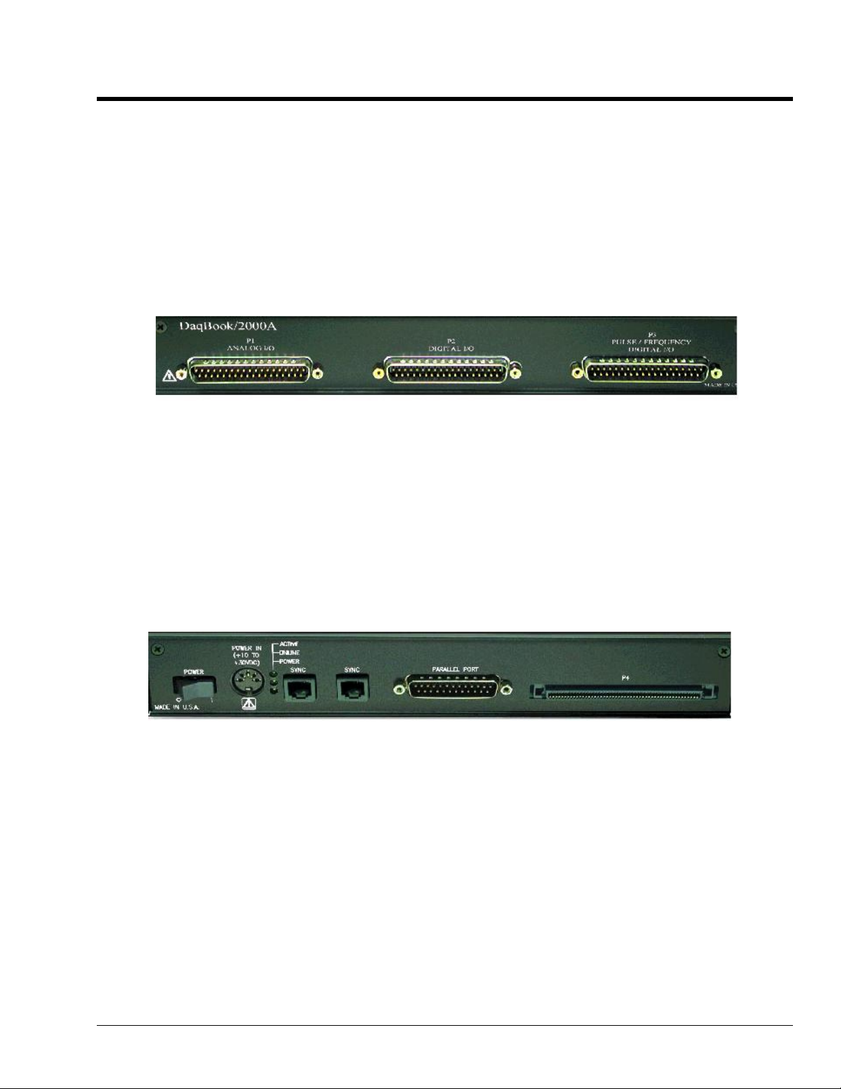
DaqBook/2000A
Front Panel
The DaqBook/2000A’s front panel offers three DB37 connectors designated as P1, P2, and P3.
P1 connects to Analog I/O.
P2 connects to Digital I/O.
P3 connects to Pulse / Frequency Digital I/O.
The
DaqBook/2000 Series User’s Manual
(p/n 1103-0901) includes pinouts for each.
Rear Panel
DaqBook/2000A’s rear panel contains a power switch, DIN5 power connector, LEDs, synchronization
ports, a parallel port connector, and a 100-pin (P4) connector. Additional detail follows. Items
described below are done so from left to right, when looking at the rear panel.
POWER Switch: A rocker-type switch with a “0” label for Power Off, and a “1” for Power On.
POWER IN: +10 to +30 VDC, through a socket type DIN5 connector on the chassis.
Power is typically supplied from a TR40U power adapter.
LEDs: ACTIVE – Lights when a sample has been converted by the A/D Converter.
ONLINE – Lights when software establishes communication to the unit.
POWER
SYNC (Qty of 2) – Two “synchronization ports” provide a means of synchronizing multiple
DaqBook/2000 Series units in regard to post-trigger scanning. The ports accept CA-74-1 and CA-74-5
RJ-11, 6 conductor type cables.
– Lights when power is turned on and is present.
Parallel Port – A DB25 connector used to connect theDaqBook/2000A to the Parallel Port of the host
PC, or to an Expansion Port of a DaqBook/2000E, or to an Expansion Port of a WBK25 Ethernet
Interface Module. Applicable cables are CA-35-2 (2-foot) and CA-35-12 (1-foot).
Appendix D
977296
Device Connector Reference D-1
Page 28

P4 – P4 is a 100-pin connector that shares signal connections with the P1, P2, and P3 connectors. P4
offers no additional I/O. You can connect a DBK200 Series Option to P4 via a CA-195 cable to
essentially distance the P1, P2, P3 connection from the DaqBook/2000A. See the following Caution.
CAUTION
Signal conflicts between a DaqBook/2000 Series device’s P1, P2, P3 connectors and its
P4 connector can result in erroneous readings and possible equipment damage.
Therefore, when connections have been made to P1, P2, and/or P3, use caution when
making connections through P4, and visa versa.
Use a CA-209D CE Cable Kit in electrically noisy environments. The kit includes a
3-foot long shielded cable, two grounding pigtails, two cable clamps, and 4 screws. The
CE Compliance chapter of the DaqBook/2000 Series User’s Manual (p/n 1103-0901)
provides additional information.
Reference Note: The document section, System Connections and Pinouts, contains pinouts for P1,
P2, P3 and P4. A copy of the document is included in
Manual (p/n 1103-0901). The manual can be viewed from the data acquisition CD via the
<View PDFs> button on the CD’s opening screen.
the DaqBook/2000 Series User’s
D-2 Device Connector Reference
977296
Appendix D
Page 29

DaqBook/2000X
Front Panel
The upper row of theDaqBook/2000X front panel contains port openings for three installed DBK cards.
In the following figure, each connector seen in the upper row belongs to an installed DBK card.
Appendix E,
DaqBook/2000X. The section includes one system example in which 3 analog DBK cards are used, and
another in which 1 analog DBK card and 2 digital DBK cards are used.
The lower row of the DaqBook/2000X front panel offers three DB37 connectors designated as P1, P2,
and P3.
P1 connects to Analog I/O.
P2 connects to Digital I/O.
P3 connects to Pulse / Frequency Digital I/O.
The DaqBook/2000 Series User’s Manual (p/n 1103-0901) includes pinouts for each.
Rear Panel
The DaqBook/2000X rear panel contains an upper section of 3 card slots and a lower section, which
includes a power switch, DIN5 power connector, LEDs, synchronization ports, a parallel port connector,
and a 100-pin (P4) connector. Items described below are done so from left to right. The top row,
consisting of three expansion slots, is listed first.
System Expansion
, contains a section entitled
Expansion via DBK Cards in a
Expansion Cards - Up to three can be added, one per card slot.
POWER Switch: A rocker-type switch with a “0” label for Power Off, and a “1” for Power On.
POWER IN: +10 to +30 VDC, through a socket type DIN5 connector on the chassis.
Power is typically supplied from a TR40U power adapter.
LEDs:
SYNC – Two “synchronization ports” provide a means of synchronizing multiple DaqBook/2000 Series
units in regard to post-trigger scanning. The ports accept CA-74-1 and CA-74-5 RJ-11, 6 conductor type
cables.
Parallel Port – A DB25 connector used to connect theDaqBook/2000X to the parallel port of the host
PC or to the EXPANSION PORT of a DaqBook/2000E. Applicable cables are CA-35-2 (2-foot) and
CA-35-12 (1-foot).
Appendix D
ACTIVE
ONLINE
POWER – Lights when power is turned on and is present.
– Lights when a sample has been converted by the A/D Converter.
– Lights when software establishes communication to the unit.
977296
Device Connector Reference D-3
Page 30

P4 – P4 is a 100-pin connector that shares signal connections with the P1, P2, and P3 connectors. P4
offers no additional I/O. You can connect a DBK200 Series Option to P4 via a CA-195 cable to
essentially distance the P1, P2, P3 connection from the DaqBook/2000X. See the following Caution.
CAUTION
Signal conflicts between a DaqBook/2000 Series device’s P1, P2, P3 connectors and its
P4 connector can result in erroneous readings and possible equipment damage.
Therefore, when connections have been made to P1, P2, and/or P3, use caution when
making connections through P4, and visa versa.
Use a CA-209D CE Cable Kit in electrically noisy environments. The kit includes a
3-foot long shielded cable, two grounding pigtails, two cable clamps, and 4 screws. The
CE Compliance chapter of the DaqBook/2000 Series User’s Manual (p/n 1103-0901)
provides additional information.
Reference Note: The document section, System Connections and Pinouts, contains pinouts for P1,
P2, P3 and P4. A copy of the document is included in the DaqBook/2000 Series User’s
Manual (p/n 1103-0901). The manual can be viewed from the data acquisition CD via the
<View PDFs> button on the CD’s opening screen.
D-4 Device Connector Reference
977296
Appendix D
Page 31

DaqBook/2000E
Front Panel
The DaqBook/2000E’s front panel offers three
DB37 connectors designated as P1, P2, and P3.
P1 connects to Analog I/O.
P2 connects to Digital I/O.
P3 connects to Pulse / Frequency Digital I/O.
The
DaqBook/2000 Series User’s Manual
Rear Panel
The upper row of DaqBook/2000E’s rear panel contains a MAC Address Label, Ethernet Port, 5 LEDs, and
three expansion ports. The lower section of the panel includes a power switch, DIN5 power connector,
3 LEDs, 2 synchronization ports, and 100-pin (P4) connector. Items described below are done so from left
to right, with the top row discussed first.
MAC Address Label: The Media Access Control (MAC) label is located in the upper left corner of the rear
panel. The label shows the device serial number in three formats: (1) Barcode, (2) base 10, and
(3) hexadecimal. If prompted to enter a serial number in software, use the base 10 number. Conversion to a
hexadecimal number for use in addressing will be automatic.
ETHERNET: The 10/100BaseT Ethernet port can connect to the Ethernet port of the host PC, or to an
Ethernet network. Either of two Ethernet patch cables may be used to make the connection. CA-242 is a
1.5 foot cable. CA-242-7 is a 7-foot cable. Note that the Ethernet connector has two built in LEDs that
indicate traffic flow. These are discussed with the three other Ethernet-related LEDs. Note that the
Ethernet cable length must be <10m in order for the system to be CE Compliant.
(p/n 1103-0901) includes pinouts for each.
LEDs: There are 5 ETHERNET Status LEDS. Two rectangular LEDs, Tx and Rx
are built right into the frame of the Ethernet jack. The other three, located
just to the right of the jack, are round and are labeled L, T, and D.
Tx – “ON” indicates traffic is being transmitted (see figure at right).
Rx – “ON” indicates that the port is receiving traffic.
L (Link) “ON” indicates a link exists. “OFF” indicates no link.
T (Transmit) “ON” indicates 100 M-Bits, “OFF” indicates 10 M-Bits.
D (Duplex) “ON” indicates full duplex, which allows simultaneous two-
EXPANSION PORTS [1, 2, and 3]: used to expand the system with up to three additional devices. These
are used to connect the DaqBook/2000E to the PARALLEL PORT connector of DaqBook/2000A and
DaqBook/2000X units.
POWER Switch: A rocker-type switch with a “0” label for Power Off, and a “1” for Power On.
POWER IN: +10 to +30 VDC, through a socket type DIN5 connector on the chassis. Power is typically
supplied from a TR40U power adapter.
Appendix D
way data traffic. “OFF” indicates half-duplex, which only allows
one-way data traffic at any given time.
977296
Tx and Rx LEDs
Device Connector Reference D-5
Page 32

LEDs: ACTIVE – Lights when a sample has been converted by the A/D Converter.
ONLINE – Lights when the DaqBook/2000E’s internal Ethernet module establishes communication
to the unit.
POWER
– Lights when power is turned on and is present.
SYNC (Qty 2) – Two “synchronization ports” provide a means of synchronizing multiple DaqBook/2000
Series units in regard to post-trigger scanning. The ports accept CA-74-1 and CA-74-5 RJ-11, 6 conductor
type cables.
P4 – P4 is a 100-pin connector that shares signal connections with the P1, P2, and P3 connectors. P4
offers no additional I/O. You can connect a DBK200 Series Option to P4 via a CA-195 cable to essentially
distance the P1, P2, P3 connection from the DaqBook/2000E. See the following Caution.
CAUTION
Signal conflicts between a DaqBook/2000 Series device’s P1, P2, P3 connectors and its
P4 connector can result in erroneous readings and possible equipment damage.
Therefore, when connections have been made to P1, P2, and/or P3, use caution when
making connections through P4, and visa versa.
Use a CA-209D CE Cable Kit in electrically noisy environments. The kit includes a
3-foot long shielded cable, two grounding pigtails, two cable clamps, and 4 screws. The
CE Compliance chapter of the DaqBook/2000 Series User’s Manual (p/n 1103-0901)
provides additional information.
Reference Note: The document section, System Connections and Pinouts, contains pinouts for P1, P2,
P3 and P4. A copy of the document is included in the DaqBook/2000 Series User’s Manual (p/n
1103-0901). The manual can be viewed from the data acquisition CD via the <View PDFs>
button on the CD’s opening screen.
D-6 Device Connector Reference
977296
Appendix D
Page 33

Appendix E – System Expansion E
Expansion via Additional DaqBook/2000 Series Devices …… E-1
Expansion via a WBK25 Ethernet Interface Module …… E-2
Expansion via DBK Modules (3 examples) …… E-3
Expansion via DBK Cards in a DaqBook/2000X (2 examples) …… E-7
How to Mount One Module to Another …… E-8
Using T-Cables …… E-9
Note: If you are not familiar with the connectors of the DaqBook/2000 Series devices, please review
Appendix D, Device Connector Reference before proceeding.
Expansion via Additional DaqBook/2000 Series Devices
The following figure represents only one of many possibly system configurations.
DaqBook/2000E
DaqBook/2000A
DaqBook/2000X
Possible DaqBook/2000 System Using /2000E, /2000A, and /2000X Units
Appendix E
968596
System Expansion E-1
Page 34

Ports and Cables for Expansion, Synchronization, and Ethernet Connection
Expansion
Expansion Port Cables are used when up to three DaqBook/2000 Series devices are to be connected to a
DaqBook/2000E via its expansion ports. The expansion port cables are the communication links that stream
acquired data back to the DaqBook/2000E and to the host PC. Note that the expansion units need not be of
the same type. Cables CA-35-2 (2-foot) and CA-35-12 (1-foot) have been approved for use as expansion
port cables.
Synchronization
SYNC Cables can be used to make several DaqBook/2000 Series devices, which are linked to each other,
scan-synchronous. Cables that have been approved for use in synchronizing DaqBook/2000 Series devices
are CA-74-1 (1-foot) and CA-74-5 (5-foot). When scan-synchronization is employed, one of the
DaqBook/2000 Series devices will be programmed as the “master.” This unit drives the acquisition timing
of the “slave” units. The section entitled Multi-DaqBook/2000 Synchronization contains detailed
information.
Ethernet Connection
Ethernet Cables intended for use with DaqBook/2000 Series devices are CA-242 (a 1.5 foot cable) and
CA-242-7 (a 7 foot cable). DaqBook/2000E can connect directly to an Ethernet port on a PC or network
hub via either cable. DaqBook/2000A and DaqBook/2000X are connected to the Ethernet when interfaced
with a DaqBook/2000E [which is connected to the Ethernet] or when connected to a WBK25 Ethernet
Interface Module. In both scenarios the DB25 Parallel Port of the DaqBook/2000A (or /2000X) device is
connected to one of three Expansion Ports located on the DaqBook/2000E [or on the WBK25]. The
connection would be made with a CA-35-2 (2-foot) or a CA-35-12 (1-foot) cable.
Expansion via a WBK25 Ethernet Interface Module
The WBK25 is a high-speed Ethernet-to-parallel port interface module. The device includes one
10/100BaseT Ethernet port for connecting to a PC Ethernet Port or Ethernet network hub. It also includes
three parallel ports, designated as “expansion ports.” Parallel cables connected to these ports can be
attached to any model of WaveBook, DaqBook, WBK40 Series option, or any combination of up to 3 of
these devices. Note that these parallel ports cannot be used to connect to auxiliary devices such as printers
and scanners.
Data transfer rates with the WBK25 depend on the network to which it is attached. If the WBK25 is used
with DaqBook/2000 Series device and WBK40 series options, then up to three of these devices can be
attached to one WBK25 and are able to transfer data at the maximum sampling rates on all three devices
simultaneously.
If the WBK25 is attached to a shared Ethernet network, then data transfer rates will be dependent on the
other network traffic at the time. It is not possible to guarantee maximum data transfer rates in this mode.
It is also possible to attach multiple WBK25 units to one PC having multiple Ethernet ports, or having a
multi-port Ethernet hub. Performance under these conditions will be dependent on the PC’s ability to handle
multiple networks.
WBK25 Ethernet-to-Parallel Port Interface
You can connect a DaqBook/2000A or a DaqBook/2000X to the Ethernet via a WBK25 Ethernet Interface
Module. To do so, the DB25 Parallel Port of a DaqBook/2000A (or /2000X) device is connected to one of
the three Expansion Ports located on the WBK25. The connection would be made with a CA-35-2 (2-foot)
or a CA-35-12 (1-foot) cable. Two additional DaqBook/2000 Series units could be connected to via the
remaining two expansion ports. These connections would also be made via a CA-35-2 or CA-35-12 cables.
The WBK25 connects directly to an Ethernet port on a PC or network hub, via the unit’s built-in
10/100BaseT Ethernet interface. An Ethernet patch cable CA-242 (1.5 foot) or CA-242-7 (7 foot) cable
is used to make the connection.
E-2 System Expansion
968596
Appendix E
Page 35

DaqBook/2000A
DaqBook/2000A
WBK25
DaqBook/2000A
Channel Input Side Device Interface Side
To ETHERNET To POWER
System with WBK25 Interface and 3 DaqBook/2000A Devices
Lines and Cables Used in the WBK25 Interface Example [Device Interface Side Only]:
1. Power Supply - To each DaqBook/2000A POWER IN DIN 5 connector, +10 VDC to +30 VDC,
and to the WBK25; typically from a TR40U power adapter.
2. From the bottom DaqBook/2000A’s PARALLEL PORT connector to EXPANSION PORT 1 on the
WBK25 Ethernet Interface Module. A CA-35-2 (2-foot) or CA-35-12 (1-foot) cable is used for this
connection.
3. From either of two SYNC Ports on the bottom DaqBook/2000A to either of two SYNC Ports on the
next DaqBook/2000A. Cable CA-74-1 (1-foot) or CA-74-5 (5-foot) is used for this connection.
4. From the available SYNC Port on the second DaqBook/2000A to either of two SYNC Ports on the
upper DaqBook/2000A. Cable CA-74-1 (1-foot) or CA-74-5 (5-foot) is used for this connection.
DaqBook/2000A
DaqBook/2000A
WBK25
DaqBook/2000A
5. From the WBK25’s EXPANSION PORT 2 to the second DaqBook/2000A’s Parallel Port.
A CA-35-2 (2-foot) or CA-35-12 (1-foot) cable is used for this connection.
6. From the WBK25’s EXPANSION PORT 3 to the third DaqBook/2000A’s Parallel Port.
A CA-35-2 (2-foot) or CA-35-12 (1-foot) cable is used for this connection.
Reference Note:
The WBK25 Ethernet-to-Parallel Port Interface is shipped with a user’s guide
(p/n 489-0903). Refer to that document for instructions regarding how to connect
a WBK25 to the Ethernet.
Expansion via DBK Modules
This section consists of three system examples, each having a figure and a corresponding list of “cables
used.”
Note that the figures and tables illustrate primary device connections to each other, they do not show signal,
power, Ethernet, or PC connections. These other types of connections are discussed elsewhere in the
document.
In regard to power, note that DaqBook/2000 Series devices can provide 15000 mW of power. This means
that many system configurations will not require additional power modules. However, to avoid the
possibility of inadequate power, you should always check power management tables prior to putting an
acquisition system together.
In regard to physically stacking modules, i.e., attaching one module to another, fastener Panels, sometimes
referred to as “splice plates,” (p/n 262-0801) are typically used. Optional handles (p/n HA-111) may also
be attached to a system.
Appendix E
968596
System Expansion E-3
Page 36

Example 1: DaqBook/2000A with a DBK1, two DBK84 Modules, and DBK203
DBK1
DBK84
DBK84
DBK203
(Note 2)
DaqBook/2000A
To POWER To PC or to /2000E
Channel Input Side Device Interface Side
DaqBook/2000A System
with a DBK1, two DBK84 Modules, and DBK203
Lines and Cables Used in Example 1 [Device Interface Side Only]:
1. Power Supply - To the DaqBook/2000A POWER IN DIN 5 connector, +10 VDC to +30 VDC,
typically from a TR40U power adapter.
2. From the DaqBook/2000A PARALLEL PORT connector, via a CA-35-x cable, to either
(a) the host PC’s PARALLEL PORT, or
(b) one of three DaqBook/2000E EXPANSION PORTS
(c) one of three WBK25 EXPANSION PORTS
DBK1
DBK84
DBK84
DBK203
(Note 2)
DaqBook/2000A
3. From DaqBook/2000A’s P4 connector to DBK203’s P4 connector, via a CA-195-1 cable.
4. From DBK203’s P1 connector to two DBK84s via two CA-37-1T cables. Connections are to the
DBK84s’ P1 connectors.
5. From the P1 connector on the upper DBK84 to the P1 connector on the DBK1, via a CA-37-1T cable.
Note 1: Information regarding the use of CA-37-T cables is provided on page IG-9.
Note 2: In reference to the above figure, it is possible to connect the two DBK84 modules and the
DBK1 module without using a DBK203. In the scenario in which the DBK203 is not used,
the DBK84 and DBK81 modules would be rotated 180° and then cabled to the
DaqBook/2000A’s P1 connector via a CA-37-3 cable.
Reference Note:
Both the DBK Option Cards and Modules User’s Manual (p/n 457-0905) and the DBK Basics
document module include power management information. You should use the Available Power Chart
and DBK Power Requirement Worktable to calculate your system’s power needs. Doing so will enable
you to ensure that adequate power will be supplied to all system components. PDF versions of both
documents are included on your data acquisition CD.
E-4 System Expansion
968596
Appendix E
Page 37

Example 2: DaqBook/2000E with a DBK41 and a DBK203
DBK41
DBK203
(Note 2)
DaqBook/2000E
To ETHERNET To POWER
DBK41
DBK203
(Note 2)
DaqBook/2000E
Channel Input Side Device Interface Side
DaqBook/2000E System
with a DBK41 and DBK203
Lines and Cables Used in Example 2 [Device Interface Side Only]:
1. Power Supply - To the DaqBook/2000E POWER IN DIN 5 connector, +10 VDC to +30 VDC,
typically from a TR40U power adapter.
2. From the DaqBook/2000E ETHERNET jack to a 10/100BaseT Ethernet Network or to the
ETHERNET jack on a PC. Applicable Ethernet patch cables (1.5-foot or 7-foot) are CA-242 and
CA-242-7, respectively.
3. From DaqBook/2000E’s P4 connector to the DBK203’s P4 connector, via a CA-195-1 cable.
4. From DBK203’s P1 connector to a DBK41’s P1 connector via one CA-37-1T cable.
Note 1: Information regarding the use of CA-37-T cables is provided on page E-9.
Note 2: In reference to the above figure, it is possible to connect the DBK41 module without using a
DBK203. In the scenario in which the DBK203 is not used, the DBK41 module would be
rotated 180° and then cabled to the DaqBook/2000E’s P1 connector via a CA-37-1 cable.
Reference Notes:
➣
➣
Appendix E
For detailed information regarding the DBK41 10-Slot Analog Expansion Module or the
DBK203 Screw-Terminal Adapter Module, refer to the DBK Option Cards and Modules User’s
Manual (p/n 457-0905). A PDF version of the document is included on the data acquisition CD.
Both the DBK Option Cards and Modules User’s Manual (p/n 457-0905) and the DBK Basics
document module include power management information. You should use the Available Power
Chart and DBK Power Requirement Worktable to calculate your system’s power needs. Doing so
will enable you to ensure that adequate power will be supplied to all system components. PDF
versions of both documents are included on your data acquisition CD.
968596
System Expansion E-5
Page 38

Example 3: DaqBook/2000E with two DBK60 Modules and a DBK203
DBK60 (1 of 2)
DBK60 (2 of 2)
DBK203
DaqBook/2000E
To ETHERNET To POWER
Channel Input Side Device Interface Side
DaqBook/2000E System
with two DBK60 units and a DBK203
Lines and Cables Used in Example 2 [Device Interface Side Only]:
1. Power Supply - To the DaqBook/2000E POWER IN DIN 5 connector, +10 VDC to +30 VDC,
typically from a TR40U power adapter.
2. From the DaqBook/2000E ETHERNET jack to a 10/100BaseT Ethernet Network or to the
ETHERNET jack on a PC. Applicable Ethernet patch cables (1.5-foot or 7-foot) are CA-242
and CA-242-7, respectively.
DBK60 (1 of 2)
DBK60 (2 of 2)
DBK203
DaqBook/2000E
3. From DaqBook/2000E’s P4 connector to the DBK203’s P4 connector, via a CA-195-1 cable.
4. From DBK203’s P1 connector to two DBK60 P1 connectors, via two CA-37-3T cables.
Note: Information regarding the use of CA-37-T cables is provided on page E-9.
Reference Notes:
➣
For detailed information regarding the DBK60 3-Slot Expansion Module and its related
Termination Panels, or the DBK203 Screw-Terminal Adapter Module, refer to the DBK Option
Cards and Modules User’s Manual (p/n 457-0905). A PDF version of the document is included
on the data acquisition CD.
➣
Both the DBK Option Cards and Modules User’s Manual (p/n 457-0905) and the DBK Basics
document module include power management information. You should use the Available Power
Chart and DBK Power Requirement Worktable to calculate your system’s power needs. Doing so
will enable you to ensure that adequate power will be supplied to all system components. PDF
versions of both documents are included on your data acquisition CD.
➣
This installation guide exists as an independent document (p/n 1103-0940). It is also included in
the DaqBook/2000 Series User’s Manual, p/n 1103-0901. The manual contains additional
information regarding DaqBook/2000 Series devices.
User’s of the independent installation guide should note that a PDF version of the DaqBook/2000
Series User’s Manual is automatically installed onto your hard drive as a part of product support.
The default location is the Programs group, which can be accessed from the Windows Desktop.
The document can also be read directly from the installation CD by using the <View PDFs>
button, accessible from the CD’s introduction screen. Refer to the PDF documentation for details
regarding both hardware and software.
E-6 System Expansion
968596
Appendix E
Page 39

cable
Expansion via DBK Cards in a DaqBook/2000X
This section consists of two DaqBook/2000X system examples. In the first example, 3 analog DBK cards are used.
In the second example, the system makes use of two digital DBK cards and one analog DBK card.
Example 1: DaqBook/2000X with 3 Analog DBK Cards
On DaqBook/2000X’s
front panel, P1 connects
to all 3 analog DBK cards
via a CA-37-3 Cable.
DaqBook/2000X with 3 Analog DBK Cards
Lines and Cables Used in Example 1:
On the Rear Panel:
1. Power Supply - To the DaqBook/2000X POWER IN DIN 5 connector, +10 VDC to +30 VDC,
typically from a TR40U power adapter.
2. From the DaqBook/2000X PARALLEL PORT connector to one of the following:
PC Parallel Port, DaqBook/2000E EXPANSION PORT, WBK25 EXPANSION PORT.
The connection is made via a CA-35-2 (2-foot cable) or a CA-35-12 (1-foot cable).
3. DBK16, DBK81, and DBK80 Analog DBK cards inserted in the DaqBook/2000X card slots;
then secured with jackscrews that are included with each card.
On the Front Panel:
From P1 to the DBK80 (located above P1), then to the DBK81 and the DBK16.
The connection is made via a CA-37-3 cable.
Example 2: DaqBook/2000X with 2 Digital DBK Cards and 1 Analog DBK Cards
On DaqBook/2000X’s
front panel, P1 connects
to the analog DBK 81
card via a CA-37-1 cable;
and P2 connects to the
DBK20 and DBK21 digital
cards via a CA-37-2
.
DaqBook/2000X with 2 Digital DBK Cards and 1 Analog DBK Card
Lines and Cables Used in Example 2:
On the Rear Panel:
Appendix E
1. Power Supply - To the DaqBook/2000X POWER IN DIN 5 connector, +10 VDC to +30 VDC,
typically from a TR40U power adapter.
2. From the DaqBook/2000X PARALLEL PORT connector to one of the following:
PC Parallel Port, DaqBook/2000E EXPANSION PORT, WBK25 EXPANSION PORT.
The connection is made via a CA-35-2 (2-foot cable) or a CA-35-12 (1-foot cable).
3. DBK21 digital, DBK20 digital, and DBK81 analog DBK cards inserted in the DaqBook/2000X
card slots.
(Continued)
968596
System Expansion E-7
Page 40

On the Front Panel:
1. From the DaqBook/2000X P1 connector to the DBK81 analog card. Connection is made
via a CA-37-1 cable.
2. From the P2 connector to the DBK20 digital card, then to the DBK21 digital card. Connection
is made via a CA-37-2 cable.
How to Mount One Module to Another
For systems that make use of several data acquisition modules, stacking units together conserves space and
simplifies cable runs. Such stacking can be facilitated with dual-lock tabs or splice plates.
• Dual-lock tabs. Dual-lock tabs, often referred to as Velcro,
stacking modules together. The tabs provide a convenient way to quickly add modules to [or remove
modules from] a system. Dual-lock tabs are often used to attach a notebook PC to a module.
• Splice Plate Kits (Fastener Panels). Optional Splice Plate Kits, also referred to as Fastener Panels,
are available through the factory. The kits include metal plates that screw into the sides of modules to
form a vertical rack of two or more modules. This method allows the “enclosure” to size itself as
needed rather than wasting space in a 1-size-fits-all type of enclosure. A handle can be attached to the
plate for convenience in portable applications.
®
provide a means of temporarily
Note that even when splice plates are used, dual-lock tabs are typically used to attach a notebook PC
to the top-level acquisition module.
Associated Part Numbers:
Splice Plate Kit: p/n 232-0810
Optional Handle: p/n HA-111
Splice Plates
Dual-lock Tabs
(To attach to
notebook PC)
Splice Plates
Optional Handle
Splice Plate Kit: p/n 232-0810
Includes 2 plates and 8 mounting
screws. The handle (HA-111) is
purchased separately.
Stacking Data Acquisition Modules
E-8 System Expansion
968596
Appendix E
Page 41

Using T-Cables
D
A T-Cable is a ribbon cable that extends the connections of one of the ports it plugs into, thus allowing a
second cable to plug into that port. The following figure clarifies the concept.
T-Cables are available in different lengths and can be used for linking two or more compatible devices
together via the device’s 37-pin digital I/O connectors.
The bottom-end of the T-Cable is a dual-connector, consisting of both a female connector, and a 37-pin
(male) connector. As seen in the following illustration, the T-Cable’s 37-pin (male) connector can be used
for “Daisy-Chain” applications.
Each T-Cable comes with three sets of screws. These are designated (in the diagram) as: short, medium, and
long. Use the short screws to secure the single, female-end of the cable to the device; and use the medium
length screws to secure a cable’s “dual-end” connector. Use the long screws for daisy-chain applications
(when you are connecting one T-Cable to another T-Cable).
CAUTION
CAUTION
CAUTIONCAUTION
Turn power OFF to the Daq devices and externally connected equipment while
connecting cables and setting configuration jumpers and switches or before opening
the lid. Electrical shock or damage to equipment can result even under low-voltage
conditions.
Tighten screws snug only; do not over-tighten!
aisy-Chain Example, Using Two T-Cables
Using two T-Cables to Connect Three Devices
Daisy-Chain Example
Appendix E
968596
System Expansion E-9
Page 42

E-10 System Expansion
968596
Appendix E
Page 43

Appendix F – Adding a Parallel Port to the PC F
If you need to connect a DaqBook/2000A or DaqBook/2000X to a notebook or desktop PC that has no parallel port
available, you can most likely use an interface device to obtain a port. To do so, your PC needs to have an available
PC-Card Slot, ISA Bus Slot, PCI Bus Slot, or an Ethernet jack. You can use one of the following devices,
depending on which type of interface applies.
WBK20A
For Interfacing with a PC-Card Slot
If you need to connect your DaqBook/2000A or
DaqBook/2000X to a notebook PC that has no
available parallel port, you can use a WBK20A.
This device consists of a PCMCIA Interface Card,
cable, and DB25 Connector.
Refer to separate instructions [supplied with the
WBK20A] if applicable.
WBK20A, Plugs into a PC-Card Slot
WBK21
For Interfacing with an ISA Bus Slot.
If you need to connect your DaqBook/2000A or
DaqBook/2000X to a desktop PC that has no
available parallel port, you may be able to use the
WBK21 option to provide a port. The board’s
connector is labeled LPT. WBK21 plugs into and
ISA Bus Slot.
Refer to separate instructions [supplied with the
WBK21] if applicable.
WBK23
For Interfacing with a PCI Bus Slot.
If you need to connect your DaqBook/2000A or
DaqBook/2000X to a desktop PC that has no
available parallel port, you may be able to use a
WBK23 to provide a port. The WBK23 plugs into
a PCI Bus Slot.
Refer to separate instructions [supplied with the
WBK23] if applicable.
Appendix F
961596
WBK21, Plugs into an ISA Bus Slot
WBK23, Plugs into a PCI Bus Slot
Adding a Parallel Port to the PC F-1
Page 44

WBK25
For interfacing with an Ethernet jack on a
PC or on a network hub.
If you are using a PC or a network with an available
Ethernet jack you can obtain three parallel ports by
using a WBK25 Ethernet-to-Parallel Port Interface.
The WBK25 provides high-speed Ethernet
connectivity for WaveBook, DaqBook, WBK40,
and WBK41 systems. Connection to the Ethernet is
made via an Ethernet patch cable, which links the
WBK25’s 10/100BaseT Ethernet port to a PC’s
Ethernet jack or an Ethernet network hub.
The WBK25 Ethernet-to-Parallel Port Interface
connects to the Ethernet and provides three
parallel ports.
The WBK25 includes three parallel ports, labeled as expansion ports 1 through 3. Each of these parallel
ports can be attached to one of the designated acquisition devices via a parallel cable. The ports cannot be
used for auxiliary devices such as printers and scanners.
Refer to separate instructions [supplied with the WBK25] if applicable.
WBK25’s three parallel ports are labeled as expansion ports 1 through 3. They are
used to connect to WaveBook, DaqBook, WBK40, and WBK41 systems via parallel
cables. The ports cannot be used for other parallel devices, such as printers and
scanners.
F-2 Adding a Parallel Port to the PC
961596
Appendix F
Page 45

Appendix G – Resource and Performance Tests G
Before you run a test
Before testing the system, make sure the device has been properly installed and powered-on. Make sure all
cables are properly and securely connected.
When testing a WaveBook or DaqBook device, if the unit does not respond within 30
seconds perform the following steps:
How to run a test
a. Open the Control Panel by navigating from the Windows’ Desktop as follows:
b. From the Control Panel, double-click the Daq* Configuration icon.
c. Select the device that you want to test from the Device Inventory configuration tree
d. Click the <Properties> button. The Properties dialog box will open.
e. Click the “Test Hardware” tab.
1) reboot the system
2) upon power-up, re-open the Daq* Configuration applet
3) select another configuration setting
4) reinitiate the test
Start Menu ⇒⇒⇒⇒ Settings ⇒⇒⇒⇒ Control Panel
(see following figure, item “c”).
f. Click the <Resource Test> button.
Preparing to Run a Resource Test
What do the tests tell me?
Resource Tests
configuration. Resource tests are pass/fail. Test failure may indicate a lack of availability of the resource,
or a possible resource conflict.
. The resource tests are intended to test system capability for the current device
Base Address Test. This resource test checks the base address for the selected port. Failure of this test may
indicate that the port is not properly configured within the system. See relevant operating system and
computer manufacturer’s documentation to correct the problem.
Appendix G
968596
Resource and Performance Tests G-1
Page 46

Interrupt Level Test
– Tests the ability of a parallel port to generate interrupts. Failure of this test may
indicate that the parallel port may be currently unable to generate the necessary hardware interrupt, while
other parallel port devices may work OK in this mode. Some parallel port devices (such as printers) do not
require interrupts to work properly. See relevant operating system and computer manufacturer’s
documentation to correct the problem.
Performance Tests
. These types of tests are intended
to check various device functions, using the current
device configuration. Performance tests provide
quantitative results for each supported functional group.
Test results represent maximum rates the various
operations can be performed. The rates depend on the
selected parallel port protocol, and vary according to
port hardware capabilities.
The ADC FIFO Input Speed part of the test results in a
display of the maximum rate at which data can be
transferred from the tested device’s internal ADC FIFO
to computer memory through the parallel port. Results
are given in samples/second, where a sample (2 bytes in
length) represents a single A/D value.
If the device has a WBK30 card installed, a WBK30
FIFO Test can be run.
WBK30 FIFO Test. This
performance test
checks the
data-storing capabilities of the optional, WBK30
memory card.
Note that the figure to the right represents results from a
previous test. Initially the screen shows no test results.
When the test is completed successfully, the
Daq*
Configuration Test Dialog Box indicates a passed
condition. For example, in the above figure:
Daq* Configuration - Test Hardware Dialog Box
WBK30 FIFO Test ÆÆÆÆ Passed.
“Passed” messages indicate that you can exit the test
program and run your application.
Reference Notes:
If you experience difficulties, please consult the additional user documentation before calling
➣
technical support. User documentation is included on your data acquisition CD, and is installed
automatically as a part of product support, when your software is installed. The default location is
the Programs Group. The documentation includes API information, pinouts, troubleshooting, and a
great deal of material regarding specific DBK cards and modules.
Documents can be read directly from the data acquisition CD via the <View PDFs> button located
➣
on the opening screen.
Hardcopy versions of the manuals can be ordered from the factory.
➣
G-2 Resource and Performance Tests
968596
Appendix G
 Loading...