

Page 1

DaqBook
Quick Start Guide
For DaqBook/100, /112, /120, /200, /216, /260*
*
Note: DaqBook/260 is shipped with an instruction guide detailing the removal of the slide-out drawer and steps for installing internal cards.
&$87,21
Turn off power to the DaqBook and externally connected equipment before connecting cables and setting
configuration jumpers and switches, and before removing the cover. Electric shock or damage to equipment can
result even under low-voltage conditions.
Take ESD precautions (packaging, proper handling, grounded wrist strap, etc.)
DaqBook Installation Steps, Pictorial Overview
(1) Set Jumpers
1. Place the unit on a flat, stable surface. Ensure no power or signal lines are connected.
2. Remove cover screw(s), and slide the to p cover plate free of the device. All ju mpers are accessible from above the board, and no
further disassembly is required.
3. Set jumpers JP1 through JP4 as needed for your application. Jumper configuration options follow shortly. Note that jumpers are
clearly labeled on the actual motherboards.
DaqBook/200, /216, and /260 do not have JP3 and JP4 jumpers. For those units, related settings are made via software.
4. Leave JP5, JP6, and JP7 in their default positions. JP5 (Time Base Selection) default position is for 1 MHz. JP6 (Watchdog Timer
Enable/Disable) default position selects “disabled.” JP7 concerns calibration. See user’s manual prior to changing the settings of
these three jumpers.
5. Replace and secure the cover before applying power and signals.
Motherboard Jumper Locations
Note that DaqBook/112 and DaqBook/216 boards are physically smaller than the other boards.
457-0941, rev 1.2
03-01-00
DaqBook Quick Start Guide 1
Page 2
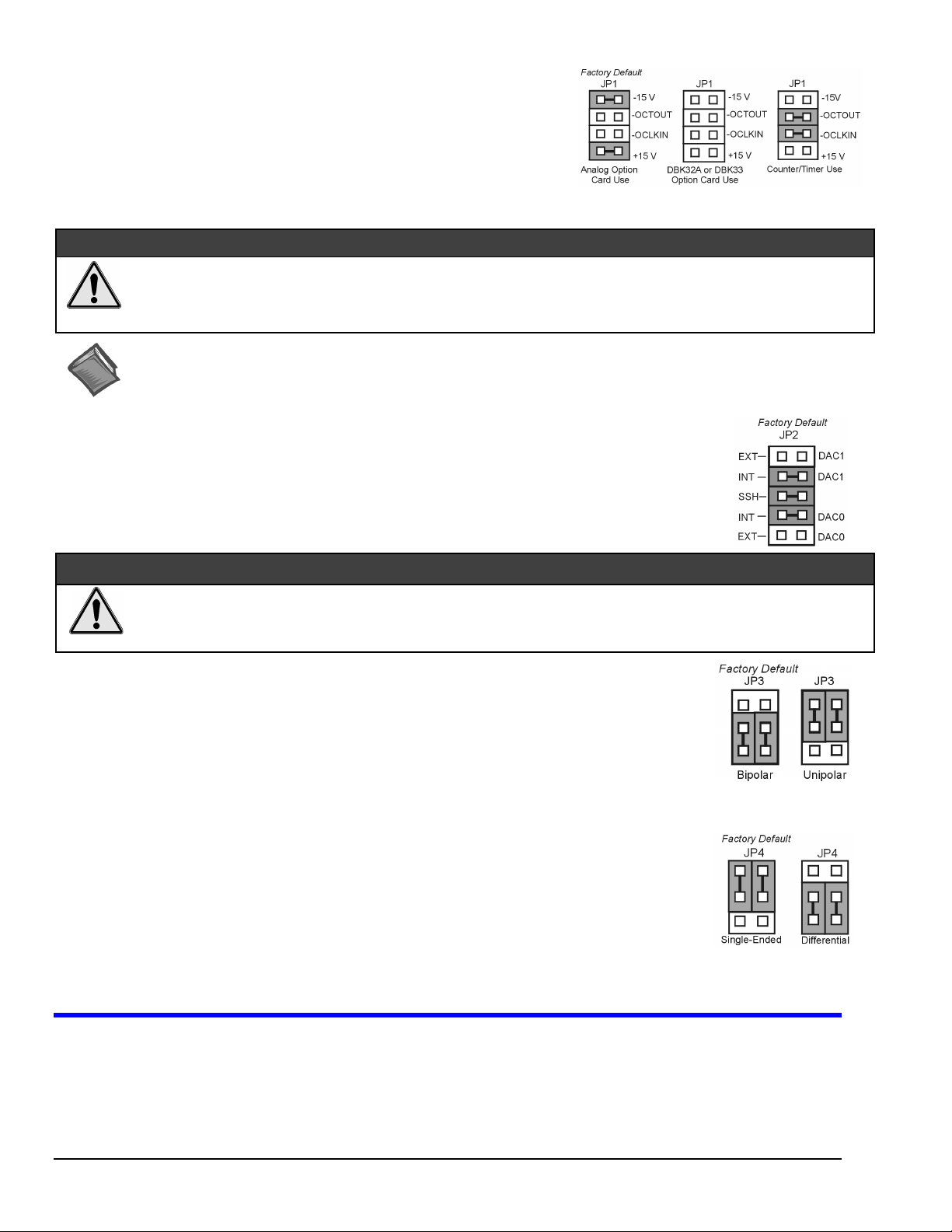
JP1 -
External Analog Expansion Power
If analog option cards (DBKs) are used
+15 and -15 VDC to the cards.
If using a DBK32A or DBK33 Power Supply Card
If no cards are being used
shown in the right-side figure.
, the counter/timer CTR0 is available, and JP1 must be set as
, JP1 jumpers are set to provide
, remove all jumpers from JP1.
&$87,21
Placing the jumpers on -OCTOUT and -OCLKIN could damage the 8254 timer chip!
Supply or a DBK33 Triple-Output Power Supply Card is used, the JP1 shunt jumpers must be removed, otherwise timer chip
damage will occur. Refer to the DBK32A, DBK33, and Power Management sections of your user’s manual for more
information.
Reference Notes:
*
proper steps for installing internal cards. (2) DBK cards and modules are available for a variety of data acquisition functions. Specific DBK
information can be found in your
programming-related information.
JP2 -
JP2 selects an
JP2 also selects
DBK2, DBK4, DBK5, DBK7, DBK17, DBK50, or DBK51.
Leave these jumpers at the factory default. Consult the user’s manual prior to making changes.
DAC Reference Voltage and SSH (Simultaneous Sample and Hold)
Internal
(default) or
SSH
(default) for applications using one or more of the following:
(1) DaqBook/260 is shipped with an additional instruction guide detailing the removal of its slide-out drawer and the
External
Daq User’s Manual
reference voltage for the two separate analog outputs.
(CD, or hard-copy version). (3) Your CD contains power management, software, and
If either a DBK32A Auxiliary Power
&$87,21
Incorrect jumper placement can damage the DaqBook!
JP2 – If EXT DAC0 or EXT DAC1 are used, the SSH jumper must be removed! See users manual for details.
•
JP3 and JP4 - Placing JP3 [or JP4] jumpers horizontally can damage DaqBook!
•
JP3 -
JP3 selects
Note
JP4 -
JP4 selects the analog input lines as 16
or 8 pairs of
If using DBK cards
If you are not using DBK cards and you want differential channels, then position the jumpers for Differential.
Note
Bipolar or Unipolar A/D Operation
Bipolar
(default) or
•
If using DBK cards
•
If you want 0-10V range
position JP3 jumpers to select
: For DaqBook/200, /216 and /260 a JP3 equivalent setting is made in software.
Unipolar
, leave these jumpers in the factory default positions.
operation for the A/D converter.
[instead of –5 V to +5 V]
Unipolar
.
and are not using DBK cards
Single-ended or Differential Analog Input Channels
Single-Ended
Differential
: For DaqBook/200, /216 and /260 a JP4 equivalent setting is made in software.
channels.
, leave these jumpers in the factory default positions.
channels (default);
,
(2) Connect PC
1. Verify DaqBook’s power switch is in the “0” (
2. Connect the female-end of the supplied cable to DaqBook’s connector labeled, “
3. Connect the male-end of the cable to an available parallel port on the PC.
2 DaqBook Quick Start Guide
and
(3) Connect Power
OFF
) position.
03-01-00
FROM PC PARALLEL PORT
.”
457-0941, rev 1.2
Page 3
4. Connect the supplied AC-to-DC adapter’s jack-end to DaqBook’s
5. Connect the adapter’s plug to a standard AC outlet.
6. To verify connections, turn ON the power switch by rotating the rocker-arm switch to the “1” position. The
light up.
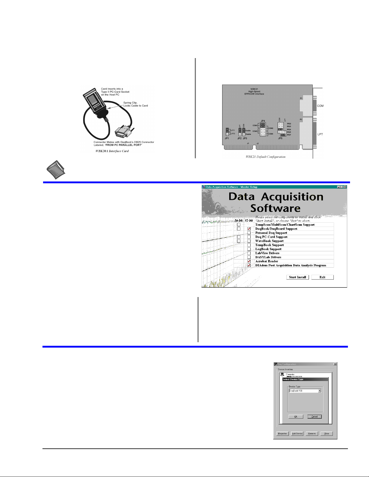
If connecting your DaqBook to a notebook PC
WBK20A, PCMCIA Interface Card. Refer to separate instruction s
(supplied with the WBK20A) if applicable.
, you can use a
POWER IN
If connecting your DaqBook to a desktop PC (with no available
EPP port),
instructions (supplied with the WBK21) if applicable.
connector.
you can use a WBK21 Interface card. Refer to separate
POWER LED
should
Reference Note:
consult the Power Management Section of your user’s manual before doing so.
It is possible to use a different VDC power source (instead of the adapter); however, you should
(4) Install Software
Remove previous version Daq* software, if present. You can do
1.
this through Microsoft’s Add/Remove Programs feature by
navigating from your desktop as follows:
Start ⇒ Settings ⇒ Control Panel ⇒ Add/Remove Programs
Place the Data Acquisition Software CD in the host PC’s
2.
CD-ROM drive.
may take a few moments, depending on your PC.
3.
If a Licensing Agreement appears, read over the agreement,
then click “Agree.” The Data Acquisition Software Master
Setup Screen appears (see figure at right).
Select
4.
5.
DaqBook/DaqBoard Support.
For Windows95/98/NT
If using Windows3.1, or DOS,
If you do not have Acrobat Reader version 3.0 or greater
installed on your PC, select
enable you to read and print documentation that is included
on the install CD-ROM.
Wait for PC to auto-access the CD. This
(or more recent Windows), select
select
Acrobat Reader
instead of 32-bit.
16-bit
. This will
32-bit
.
6.
Select
DIAdem Post Acquisition Data Analysis
Program
. Refer to your separate DIAdem document
(p/n 457-0903) for information regarding DIAdem.
7. Click “
8. Follow screen prompts.
Start Install
.”
(5) Test Hardware
1. Run the
2. Click “
3. Select your DaqBook model from the “
4. Select your DaqBook from the “
5. Ensure settings are correct, and make changes if needed.
6. Select the
7. Verify DaqBook has been properly installed and powered-on. Make sure the parallel port cable
457-0941, rev 1.2
Daq Configurati o n
Add Device
Test Hardware
is firmly in place on both th e DaqBook and the hos t PC’s LPT port.
.”
control panel applet.
Device Type
Device Inventory
tab.
03-01-00
” scroll box and click OK.
” window and click “
Properties
.”
Device Type Window
DaqBook Quick Start Guide 3
Page 4
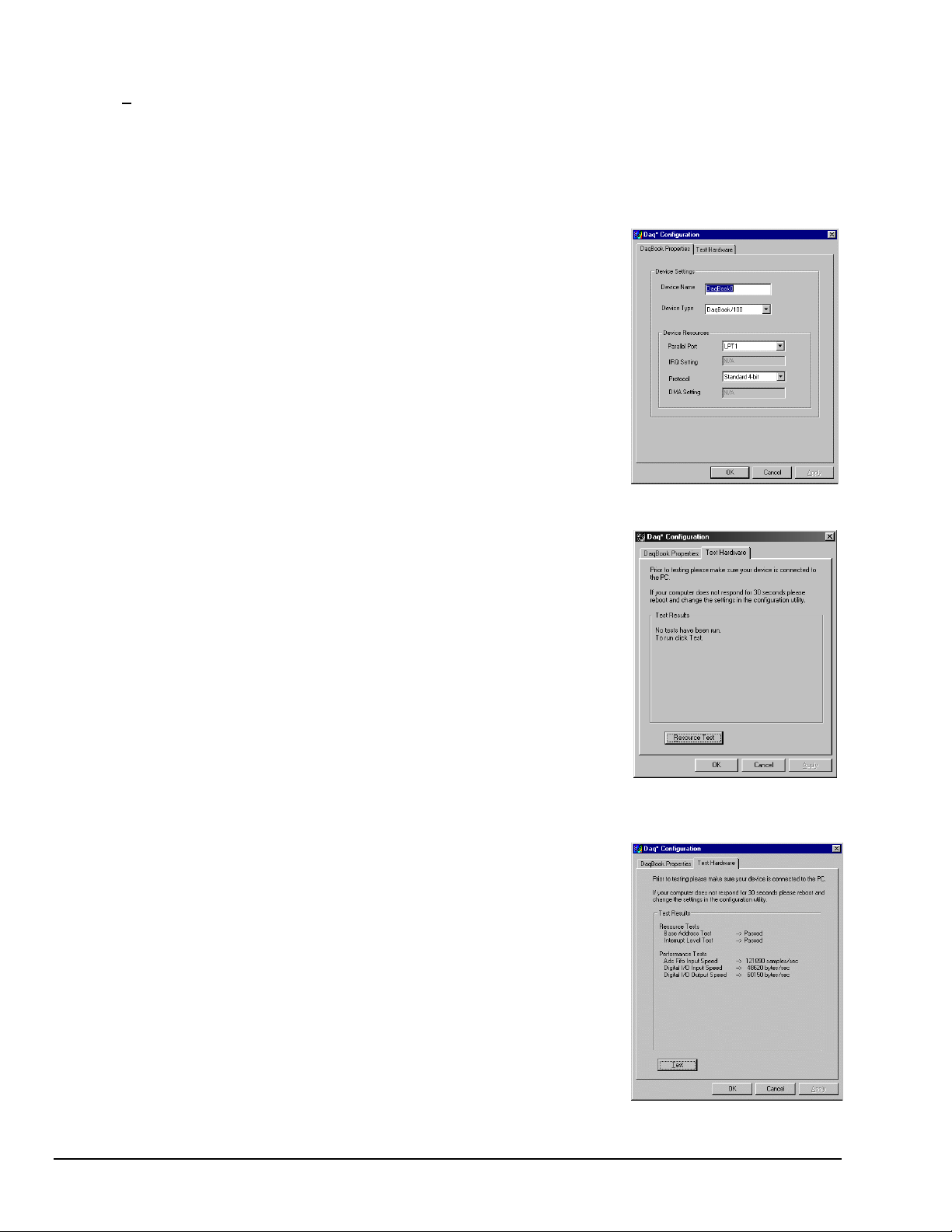
Click the “
8.
9. Click the
Test results should be displayed within a few seconds.
Note that test results have two components:
Note:
Resource Test
button.
Test
Testing the DaqBook device may, in some cases, cause the system to hang. If test results are not displayed in 30 seconds or the
system does not seem to be responding, reboot the system. Upon power-up, re-enter the Daq Configuration and change the
DaqBook configuration settings to those that work properly.
” button. This begins the test on DaqBook.
Resource Tests
and
Performance Tests.
Each is described below.
Resource Tests
Resource tests are intended to test system capability for the current device configuration. These
tests are pass/fail. Resource test failure may indicate a lack of resource availability or a resource
conflict.
Tests the base address for the selected parallel port. Failure of this test
–
Base Address Test
may indicate that the parallel port is not properly configured within the system. See relevant
operating system and computer manufacturer’s documentation to correct the problem.
Interrupt Level Test
this test may indicate that the parallel port may be currently unable to generate the necessary
hardware interrupt, while other parallel port devices may work OK in this mode. Some parallel
port devices (such as printers) do not require interrupts to work properly. See relevant operating
system and computer manufacturer’s documentation to correct the problem.
Tests the ability of the parallel port to generate interrupts. Failure of
–
DaqBook Properties Tab
Performance Tests
Performance tests are intended to test various DaqBook functions with the current device
configuration. These tests give quantitative results for each supported functional group. The
results represent maximum rates at which the various operations can be performed. These rates
depend on the selected parallel port p rotocol and will vary according to port hardware capabilities.
tests the maximum rate at which data can be transferred from the
–
ADC FIFO Input Speed
DaqBook’s internal ADC FIFO to computer memory through the parallel port. Results are given
in samples/second, where a sample (2 bytes in length) represents a single A/D value.
Digital I/O Input Speed
from the DaqBook’s Digital I/O ports to computer memory through the parallel port. Results are
given in bytes/second.
Digital I/O Output Speed
transferred from the computer’s memory to the DaqBook’s Digital I/O ports through the parallel
port. Results are given in bytes/second.
tests the maximum rate at which DIO input data can be transferred
–
tests the maximum rate at which DIO output data can be
–
Test Hardware Tab
Test Results
If you experience difficulties, please consult your user documentation (on CD, or hardcopy) before calling technical support.
Note:
User documentation includes troubleshooting, as well as a great deal of information regarding specific DBK cards and modules.
4 DaqBook Quick Start Guide
03-01-00
457-0941, rev 1.2
 Loading...