

Page 1
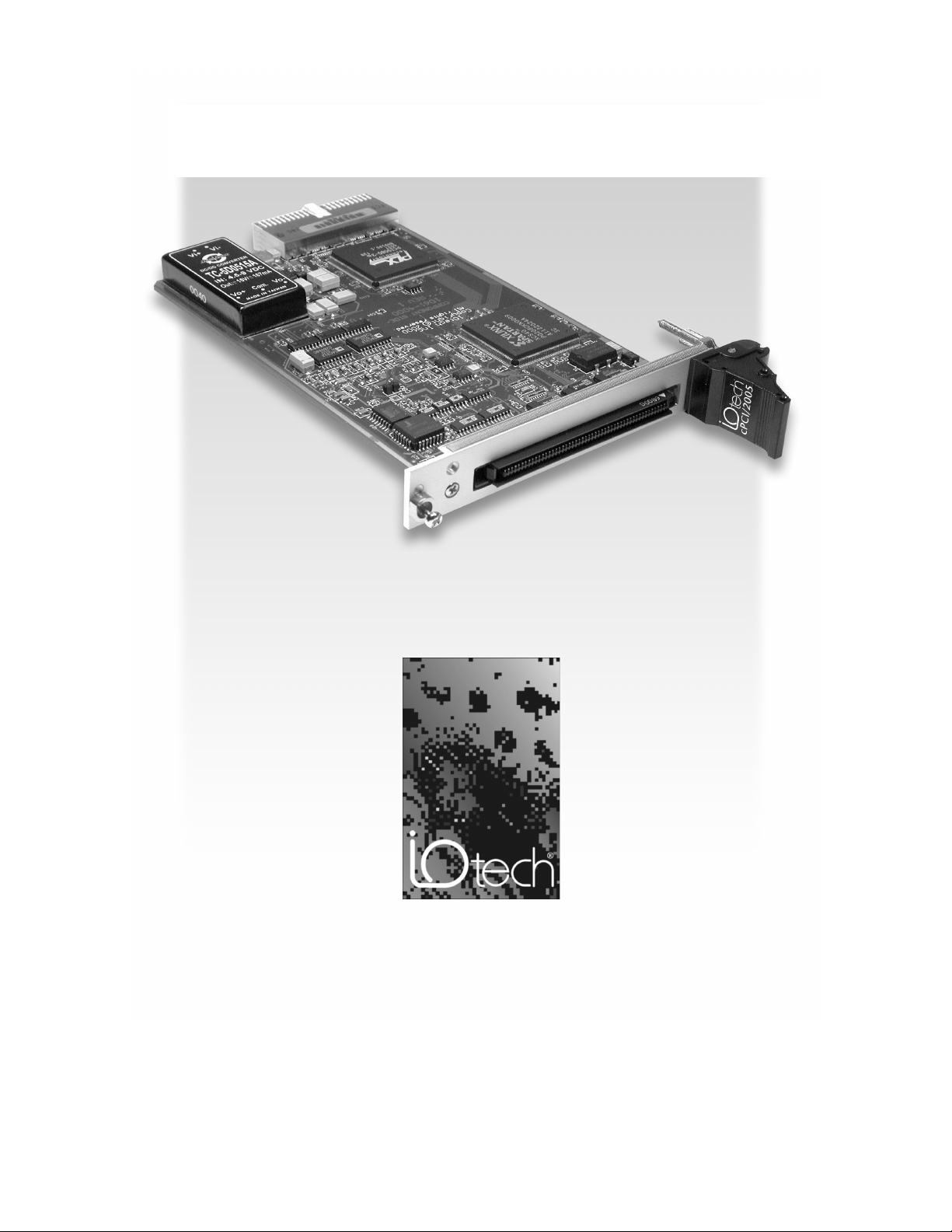
DaqBoard/2000c Series
Compact-PCI Data Acquisition Boards
Installation Guide
the smart approach to instrumentation
IOtech, Inc.
25971 Cannon Road
Cleveland, OH 44146
Ph: (440) 439-4091
Fax: (440) 439-4093
E-mail (Product Information):
E-mail (Technical Support):
Internet:
© 2001, 2002 by IOtech, Inc. October 2002
productsupport@iotech.com
www.iotech.com
™
sales@iotech.com
1061-0940
,
rev.
3.0
Page 2
Warranty Information
Your IOtech warranty is as stated on the
fax machine, or e-mail in regard to warranty-related issues.
Phone: (440) 439-4091, fax: (440) 439-4093, e-mail: sales@iotech.com
product warranty card
Limitation of Liability
IOtech, Inc. cannot be held liable for any damages resulting from the use or misuse of this product.
Copyright, Trademark, and Licensing Notice
All IOtech documentation, software, and hardware are copyright with all rights reserved. No part of this product may be
copied, reproduced or transmitted by any mechanical, photographic, electronic, or other method without IOtech’s prior written
consent. IOtech product names are trademarked; other product names, as applicable, are trademarks of their respective
holders. All supplied IOtech software (including miscellaneous support files, drivers, and sample programs) may only be used
on one installation. You may make archival backup copies.
FCC Statement
IOtech devices emit radio frequency energy in levels compliant with Federal Communications Commission rules (Part 15) for
Class A devices. If necessary, refer to the FCC booklet
004-000-00345-4) which is available from the U.S. Government Printing Office, Washington, D.C. 20402.
CE Notice
Many IOtech products carry the CE marker indicating they comply with the safety and emissions standards of the European
Community. As applicable, we ship these products with a Declaration of Conformity stating which specifications and operating
conditions apply.
. You may contact IOtech by phone,
How To Identify and Resolve Radio-TV Interference Problems
(stock #
Warnings, Cautions, Notes, and Tips
Refer all service to qualified personnel. This caution symbol warns of possible personal injury or equipment damage under
noted conditions. Follow all safety standards of professional practice and the recommendations in this manual. Using this
equipment in ways other than described in this manual can present serious safety hazards or cause equipment damage.
This warning symbol is used in this manual or on the equipment to warn of possible injury or death from electrical shock under
noted conditions.
This ESD caution symbol urges proper handling of equipment or components sensitive to damage from electrostatic discharge.
Proper handling guidelines include the use of grounded anti-static mats and wrist straps, ESD-protective bags and cartons, and
related procedures.
This symbol indicates the message is important, but is not of a Warning or Caution category. These notes can be of great
benefit to the user, and should be read.
In this manual, the book symbol always precedes the words “Reference Note.” This type of note identifies the location of
additional information that may prove helpful. References may be made to other chapters or other documentation.
Tips provide advice that may save time during a procedure, or help to clarify an issue. Tips may include additional reference.
Specifications and Calibration
Specifications are subject to change without notice. Significant changes will be addressed in an addendum or revision to the
manual. As applicable, IOtech calibrates its hardware to published specifications. Periodic hardware calibration is not
covered under the warranty and must be performed by qualified personnel as specified in this manual. Improper calibration
procedures may void the warranty.
Quality Notice
IOtech has maintained ISO 9001 certification since 1996. Prior to shipment, we thoroughly test our products and review our
documentation to assure the highest quality in all aspects. In a spirit of continuous improvement, IOtech welcomes your
suggestions.
During software installation, Adobe® PDF versions of user manuals are automatically installed onto your hard drive as a part
of product support. The default location is in the
copy of the Adobe Acrobat Reader® is included on your CD. The Reader provides a means of reading and printing the PDF
documents. Note that hardcopy versions of manuals can be ordered from the factory.
IG-ii DaqBoard/2000c Series Installation Guide
Programs
10-17-02
directory, which can be accessed from the Windows Desktop. A
1061-0940, rev 3.0
Page 3
Your order was carefully inspected prior to shipment. When you receive your system, carefully
unpack all items from the shipping carton and check for physical signs of damage that may have
occurred during shipment. Promptly report any damage to the shipping agent and your sales
representative. Retain all shipping materials in case the unit needs returned to the factory.
&$87,21
Using this equipment in ways other than described in this manual can cause
personal injury or equipment damage. Before setting up and using your
equipment, you should read all documentation that covers your system.
Pay special attention to Warnings and Cautions.
Note:
During software installation, Adobe
automatically install onto your hard drive as a part of product support. The default
location is in the Programs group, which can be accessed from the Windows
Desktop. Initial navigation is as follows:
Start [Desktop “Start” pull-down menu]
⇒
Programs
⇒
IOtech DaqX Software
You can also access the PDF documents directly from the data acquisition CD by
using the <View PDFs> button located on the opening screen.
®
PDF versions of user manuals will
PDF
1033-0901
PDF
457-0909
PDF
1086-0926
1086-0922
Refer to the PDF documentation for details regarding both hardware and software.
A copy of the Adobe Acrobat Reader
®
is included on your CD. The Reader
provides
a means of reading and printing the PDF documents. Note that hardcopy versions
of the manuals can be ordered from the factory.
DaqBoard 2000 Series and
DaqBoard/2000c Series User’s Manual.pdf
Contains the DaqBoard/2000 Series and cPCI DaqBoard/2000c Series hardwarerelated and software-related chapters, as well as links to the .pdf files listed below.
This pdf file, plus the following constitute a complete set of documentation for the
DaqBoard/2000 Series boards and the cPCI DaqBoard/2000c Series boards. Note that
the Programmer’s Manual (1008-0901) and the DBK Option Cards & Modules
(457-0905) are completely separate documents.
DaqView_DaqViewXL.pdf
Discusses how to install and use these “out-of-the-box” data acquisition programs.
PostAcquisition Analysis.pdf
This pdf consists of two documents. The first discusses eZ-PostView, a post data
acquisition analysis program. The application is included free as a part of DaqTemp
product support. The second includes information regarding eZ-FrequencyView and
eZ-TimeView. These two applications have more features than does eZ-PostView and
are available for purchase. They can; however, be used freely during a 30-day trial
period.
1061-0940, rev3.0
10-17-02
DaqBoard/2000c Series Installation Guide IG-iii
Page 4

PDF
457-0905
PDF
1008-0901
DBK Options.pdf
The DBK Option Cards and Modules Manual discusses each of the DBK products
available at the time of print.
Programmers Manual.pdf
The programmer’s manual pertains to developing custom programs using Applications
Program Interface (API) commands.
Programmers should check the
program examples included on the CD.
readme.file
on the install CD-ROM for the location of
IG-iv DaqBoard/2000c Series Installation Guide
10-17-02
1061-0940, rev 3.0
Page 5
DaqBoard/2000c Series Installation
This guide tells you how to complete the following steps for a successful installation.
Step 1 – Install Software
Step 2 – Install Boards into Available, 5 Volt, Compact-PCI Bus-Slots
Step 3 – Configure Boards
Step 4 – Test Hardware
…… page 2
…… page 2
….. page 4
….. page 5
Reference Note:
After you have completed the installation you should refer to the electronic documents that
were automatically installed onto your hard drive as a part of product support. The default
location is in the Programs directory, which can be accessed from the Windows Desktop.
You should keep your DaqBoard/2000c Series board’s serial number and your DaqView/2000 authorization
code (if applicable) with this document. Space is provided below for recording up to 4 board numbers and
their compact-PCI bus-slot location. Board serial numbers are located on the 100-pin P4 connector.
Board Type
e.g., DaqBoard/2005c
Board 1
Board 2
Board 3
Board 4
Compact PC support for DaqBoard/2000c Series boards varies. A system can support no more than four boards.
Serial Number Compact-PCI Bus-Slot Location
*Note: The DaqBoard/2000c Series boards have their board identity indicated on the latch, as indicated in
the photo on the front page of this guide. This identification is provided since the boards look very
much alike and are visually identical once installed.
DaqView/2000 Authorization Code
Customers who ordered DaqView/2000 can find their authorization code on the
sleeve of the install CD. Customers who did not order DaqView/2000 can run a
user’s manual.
____________________________
&$87,21
Take ESD precautions (packaging, proper handling, grounded wrist strap, etc.)
Use care to avoid touching board surfaces and onboard components. Only handle
boards by their edges (or ORBs, if applicable). Ensure boards do not come into contact
with foreign elements such as oils, water, and industrial particulate.
Reference Note:
During software installation, Adobe
onto your hard drive as a part of product support. The default location is in the Programs
directory, which can be accessed from the Windows Desktop. A copy of the Adobe Acrobat
®
Reader
is included on your CD. The Reader provides a means of reading and printing the
PDF documents. Note that hardcopy versions of manuals can be ordered from the factory.
Note: In regard to functionality, the DaqBoard/2000c Series boards are identical to their
DaqBoard/2000 Series counterparts.
®
PDF versions of user manuals are automatically installed
authorization code sheet
30-day free trial version
located inside the
, as discussed in the
© 2001, 2002 by IOtech, Inc. October 2002
1061-0940
,
rev.
3.0
IG-1
Page 6

Reference Notes:
➣
Each DaqBoard/2000c Series Board plugs into a 5 volt, compact-PCI bus-slot located on the PC’s backplane. Note that
the 5 V compact-PCI bus-slot contains a blue key (see page 3). Consult your PC owner’s manual as needed.
➣
Be sure to read about the DBK cards and modules applicable to your acquisition system. Specific DBK information can
be found in on the world wide web at http://www.daqboard.com; and in your
Manual
(p/n 457-0905). After the install you can navigate to the DBK manual and other relevant electronic documents
from your desktop as follows:
Start ⇒ Programs ⇒ IOtech DaqX Software ⇒ DaqBoard 2000 Series Users
Reference Note
automatically install onto your hard drive as a part of product
support. The default location is in the
can be accessed from the
documentation for details regarding both hardware and software.
Note that hardcopy versions of the manuals can be ordered from
the factory.
: Adobe PDF versions of user manuals will
Programs
Windows Desktop
group, which
. Refer to the PDF
DBK Option Cards and Modules User’s
Minimum System Requirements
PC system with Pentium® Processor
Windows Operating System
RAM, as follows:
32 Mbytes of RAM for Windows 95/98/NT
64 Mbytes of RAM for Windows Me
64 Mbytes of RAM for Windows 2000
64 Mbytes of RAM for Windows XP
Step 1
Step 2
– Install Software
IMPORTANT: Software must be installed before installing hardware.
Remove
1.
Programs
2. Place the Data Acquisition CD into the CD-ROM drive.
take a few moments, depending on your PC.
Start/Run/Browse feature.
3. After the intro-screen appears, follow the screen prompts.
Upon completing the software installation, continue with step 2,
Compact-PCI Bus-slots
previous version Daq drivers, if present. You can do this through Microsoft’s
feature.
Wait for PC to auto-run the CD. This may
If the CD does not auto-run, use the Desktop’s
Install Boards in available 5 Volt,
.
– Install Boards in available 5 Volt, Compact-PCI Bus-slots
IMPORTANT: Software must be installed before installing hardware.
IMPORTANT: Bus Mastering DMA
For a DaqBoard/2000c Series board to operate properly, Bus Mastering DMA
Prior to installation, verify that your computer is capable of performing Bus Mastering DMA for
the applicable compact-PCI bus-slot. Note that some computers have BIOS settings that enable
[or disable] Bus Mastering DMA. If your computer has this BIOS option, ensure that Bus
Mastering DMA is
Refer to your PC’s owner manual for additional information regarding Bus Mastering DMA.
Enabled
on the appropriate compact-PCI bus-slot.
must be
Enabled
.
must be enabled
Add/Remove
.
IMPORTANT: The Compact-PCI Bus-Slot must be keyed for 5 Volt use.
Note
: The 5 Volt Key location is indicated in the first photograph on page 3.
IG-2 DaqBoard/2000c Series Installation Guide
10-17-02
1061-0940, rev 3.0
Page 7
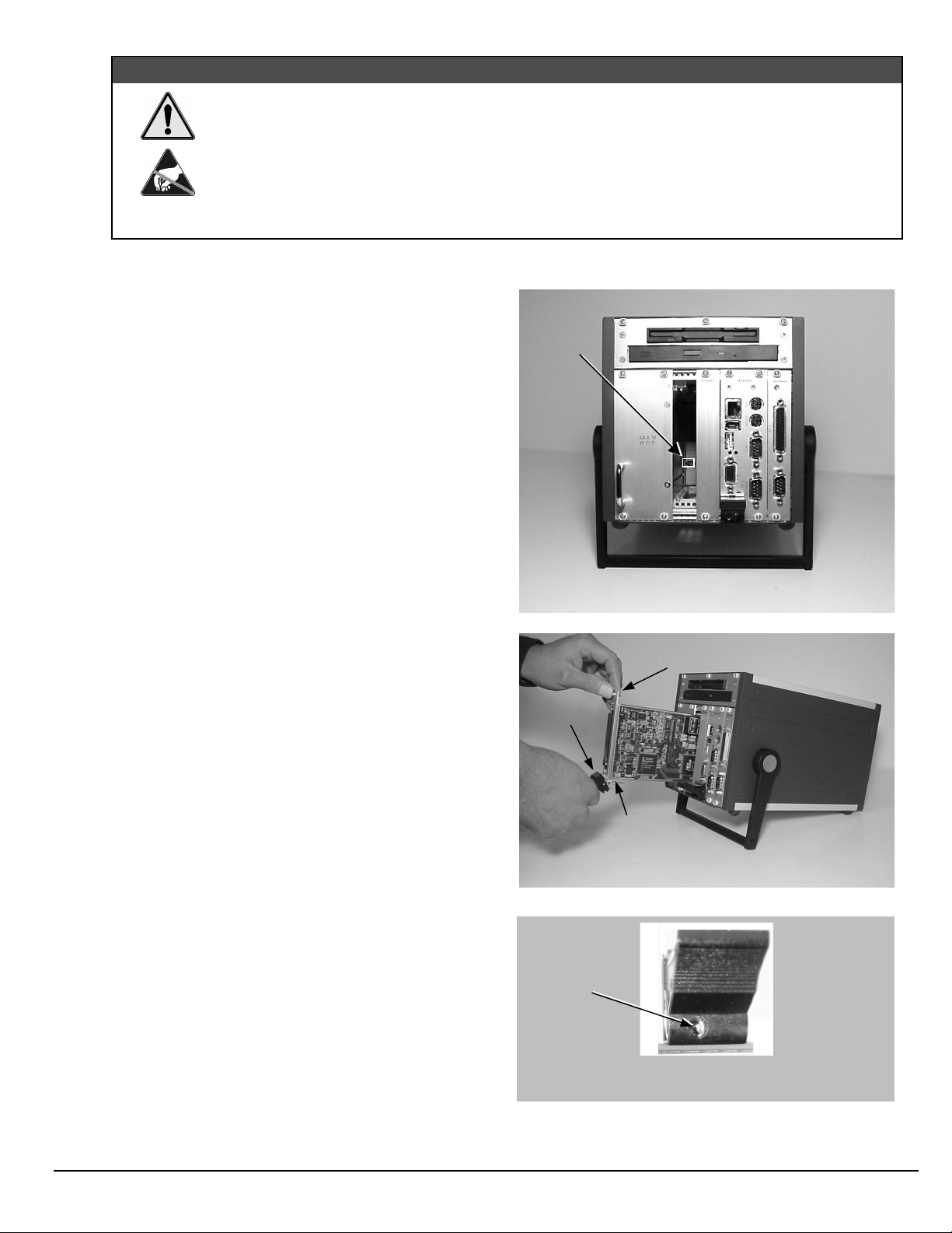
&$87,21
Turn power OFF, and UNPLUG the host PC and externally connected equipment prior to
removing any cover plates or modules. Electric shock or damage to equipment can result even
under low-voltage conditions.
Take ESD precautions (packaging, proper handling, grounded wrist strap, etc.)
Use care to avoid touching board surfaces and onboard components. Only handle boards by their
edges or ORBs. Ensure boards do not come into contact with foreign elements such as oils, water,
and industrial particulate.
1. Turn the PC’s power
2. Turn
3.
power OFF
UNPLUG the host PC
OFF
.
to externally connected equipment.
and all externally connected
equipment.
4. Remove the computer’s compact-PCI bus-slot cover plate
[or remove an unwanted module, if applicable].
Refer to your PC Owner’s Manual as needed
.
5. Verify that the available compact-PCI bus slot is for
5 volt applications.
The computer’s 5 volt compact-PCI bus-slots can be
recognized by a blue voltage key that is located in the
center of the slot (see figure).
6. Carefully remove the DaqBoard/2000c Series Board from
its anti-static protective bag. If you have not already done
so, write down the serial number of your board at this
time. The serial number is located on the 100-pin P4
connector.
7. With the board’s
injector/ejector
down, guide the board
into the PC’s slot. Note that the top and bottom edges of
the board locate in edge-guides, within the PC.
8. Push the board back into the PC to engage the board’s
compact-PCI connector with the computer’s compact-PCI
bus-slot.
9. Pull the board’s
injector/ejector
up. This will fully
engage the connectors.
10. Secure the board by tightening the upper and lower lock
screws.
11. Using the previous steps, install additional boards into
available compact-PCI bus-slots, if applicable to your
application.
Note
: The lower lock screw is accessed through an opening
injector/ejector
on the
as indicated in the right-hand
figure.
Voltage
Key
Compact-PCI Bus-Slot with Blue 5 Volt Identifier Key
Upper Lock Screw
Injector/
Ejector
Lower Lock Screw
(see note)
Installing a DaqBoard/2000c Series Board
Lower Lock
Screw
1061-0940, rev3.0
10-17-02
Injector/Ejector and Lower Lock Screw
DaqBoard/2000c Series Installation Guide IG-3
Page 8

12. Plug in all cords and cables that were removed in step 3.
q
13. Apply power to, and start up the PC.
Note
: At this point some PCs may prompt you to insert an
installation disk. While this is rare, if you do receive
such a prompt simply place the install CD into the disk
drive and follow the screen prompts.
Board/2000c Series Board
Step 3
Securing a Da
– Configure Boards
DaqBoard/2000c Series boards have no jumpers or switches to set. Configuration is performed entirely through software.
Refer to the following figure and steps to complete the configuration. The numbers in the figure correspond to the numbered
steps immediately following the figure.
Accessing the DaqBoard/2000 Properties Tab
IG-4 DaqBoard/2000c Series Installation Guide
10-17-02
1061-0940, rev 3.0
Page 9

1. Run the
Start ⇒ Settings ⇒ Control Panel ⇒ Daq*Configuration (double-click)
2. Double-click on the Device Inventory’s DaqBoard2K0 icon. The DaqBoard/2000 Properties tab (used for the entire
DaqBoard/2000 Series) will appear.
provided below.
3. Enter a “
DaqBoard/2000 Series board. Note that Device Name actually refers to the PCI slot and not to the actual board.
4. Verify that the “Device Type” shows the correct DaqBoard/2000 Series board, e.g., “DaqBoard/2000, DaqBoard/2001, etc.”
Note that available device types can be viewed via the pull-down list (▼).
5. Confirm that the DaqBoard/2000 Series text box shows a
If this text box is empty
Refer to the inside front cover page for serial number information.
Daq Configuration
Device Name
” in the text box, or use the default “DaqBoard2K0.” Device Name is for identifying the specific
, use its pull-down list (▼) and select the serial number that matches the one for your board.
control panel applet. Navigation from the desktop to the applet is as follows:
If the DaqBoard2K0 icon is not present, skip to the Using ‘Add Device’ section
Bus #, Slot #,
Serial Number
and
.
Using “Add Device”
This method is for users who have accessed the
applet, but have no DaqBoard2K icon (as described in
step 2, above).
(A) After accessing the Daq Configuration control panel applet, click on the Add
Device button (see figure, right). The
(B) Using the
example at the right
(C) Click the OK button. The DaqBoard/2000 Properties tab will appear. This tab
applies to all boards in the DaqBoard/2000 Series.
At this point, complete steps 3 through 5 from above.
Device Type’s
DaqBoard/2000
pull-down list, select the applicable board. In the
Daq Configuration
Select Device Type
is selected.
control panel
window will appear.
Using “Add Device’
Step 4
Use the following steps to test the DaqBoard/2000 Series board. Note that these steps are continued from those listed under
the previous section, “Configure Board.”
Note:
At this point we are ready to connect signals. This is typically accomplished with the use of a DBK200 Series option.
–
Test Hardware
1. Select the “
2. Click the “
3. After the test is complete, click “OK.”
System capability is now tested for the DaqBoard/2000
Series board and a list of test results appears on screen.
If you experience difficulties, please consult your user
documentation (included on your CD) before calling for
technical support. Note that the user documentation
includes a troubleshooting chapter, as well as a great
deal of information regarding specific DBK cards and
modules.
Test Hardware”
Resource Test
Reference Note
For detailed information regarding the DBK200 Series options, refer to the
User’s Manual
During software installation, Adobe® PDF versions of user manuals are automatically installed onto your hard
drive as a part of product support. The default location is in the
from the Windows Desktop. A copy of the Adobe Acrobat Reader® is included on your CD. The Reader
provides a means of reading and printing the PDF documents. Note that hardcopy versions of manuals can be
ordered from the factory.
:
(p/n 457-0905).
tab.
” button.
Test Hardware Tab (Condensed Screen Image)
DBK Option Cards and Modules
Programs
directory, which can be accessed
1061-0940, rev3.0
10-17-02
DaqBoard/2000c Series Installation Guide IG-5
Page 10

IG-6 DaqBoard/2000c Series Installation Guide
10-17-02
1061-0940, rev 3.0
Page 11

1061-0940, rev3.0
10-17-02
DaqBoard/2000c Series Installation Guide IG-7
Page 12

IG-8 DaqBoard/2000c Series Installation Guide
10-17-02
1061-0940, rev 3.0
 Loading...