

Page 1

PCM-DAS16D/12
PCM-DAS16S/12
ComputerBoards, Inc.
Revision 4
July, 1999
Page 2

All rights reserved. No part of this publication may be reproduced, stored in a retrieval system,
or transmitted, in any form by any means, electronic, mechanical, by photocopying, recording
or otherwise without the prior written permission of ComputerBoards, Inc.
MEGA-FIFO, the CIO prefix to data acquisition board model numbers, the PCM prefix to data
acquisition board model numbers, PCM-DAS08, PCM-D24C3, PCM-DAC02, PCM-COM422,
PCM-COM485, PCM-DMM, PCM-DAS16D/12, PCM-DAS16S/12, PCM-DAS16D/16,
PCM-DAS16S/16, Universal Library, Instacal, Harsh Environment Warrant y and
ComputerBoards are registered trademarks of ComputerBoards, Inc.
IBM, PC and PC/ AT are trademarks of Internati onal Business Machines Corp .
Windows is a trademark of Microsoft Corp.
Information furnished by ComputerBoards, Inc. is believed to be accurate and reliable;
however, no responsibility is assumed by ComputerBoards, Inc. for its use; nor for any
infringements of patents or other rights of third parties which may result from its use. No
license is granted by implication or otherwise under any patent or copyrights of
ComputerBoards, Inc.
These warranties are in lieu of all other warranties, expressed or implied, including any implied warranty
of merchantability or fitness for a particular application. The remedies provided herein are the buyer’s
sole and exclusive remedies.
Neither ComputerBoards, Inc., nor its employees shall be liable for any direct or indirect, special,
incidental or consequential damage arising from the use of its products, even if ComputerBoards has
been notified in advance of the possibility of such damages.
Notice
ComputerBoards, Inc. does not authorize any ComputerBoards, Inc.
product for use in life support systems and/or devices without the
written approval of the President of ComputerBoards, Inc. Life support
devices/systems are devices or systems which, a) are intended for
surgical implantation into the body, or b) support or sustain life and
whose failure to perfo rm can be reasonably expected to result in in jury.
ComputerBoards, Inc. products are not designed with the components
required, and are not subject to the testing required to ensu re a level of
reliability suitable for the treatment and diagnosis of people.
(C) Copyright 1999 ComputerBoards, Inc.
No part of this manual may be reproduced without written permission from ComputerBoards, Inc.
HM PCM-DAS16x_12.lwp
Page 3

Table of Contents
2.1 INSTALL THE InstaCal™ SOFTWARE
PACKAGE ......................................
4.1.1 Single-Ended and Differential Inputs
4.1.1 Single-Ended Inputs
4.1.2 Differential Inputs
4.1.3 System Grounds and Isolation
4.1.4 Which system do you have?
..........................
............................
.................
...................
4.1.5 Systems with Common Grounds
............
...............
4.1.6 Systems with Common Mode (Offset V’s)
4.1.7 Small Common Mode Voltages
4.1.8 Large Common Mode Voltages
4.1.9 PCM-DAS16x/12 and Signal Source
................
................
...........
4.2.1 Common Ground / Single-Ended Inputs
4.2.2 Common Ground / Differential Inputs
4.2.3 Common Mode Voltage < ±10V / SE
4.2.4 Common Mode Input < ±10V / Diff
4.2.5 Common Mode Voltage > +/-10V
...........
...........
............
............
4.2.6 Isolated Grounds / Single-Ended Inputs
4.2.7 Isolated Grounds / Differential Inputs
...........
........
.......
.........
.........
1y 1 INTRODUCTION ....................................
22 INSTALLATION .................................
2
2 2.2 INSTALL THE PCMCIA CARD ....................
43 I/O CONNECTOR .................................
74 ANALOG CONNECTIONS .........................
7 4.1 ANALOG INPUTS ................................
7
8
9
10
11
12
13
13
13
14
15 4.2 WIRING CONFIGURATIONS ......................
15
16
16
17
17
18
19
205 PROGRAMMING & APPLICATIONS ...............
20 5.1 PROGRAMMING LANGUAGES ...................
20 5.2 PACKAGED APPLICATIONS PROGRAMS ..........
216 CALIBRATION ..................................
21 6.1 SOFTWARE CALIBRATION .......................
227 I/O ADDRESS MAP & REGISTER FUNCTIONS .........
22 7.1 CONTROL REGISTERS ...........................
258 CABLE & SCREW TERMINAL BOARD .............
269 SPECIFICATIONS ................................
Page 4

Page 5

1 INTRODUCTION
1
The PCM-DAS16x/12 is a data acquisition and control board for IBM PC
compatible computers with PCMCIA type 2 slots. The heart of the board is
an analog to digital converter. Analog signals are routed to the A/D via either
an 8:1 differential multiplexor (on the PCM-DAS16D/12) or a 16:1 single
ended multiplexor (on the PCM-DAS16S/12) controlled by a register on the
PCM-DAS16x/12. (These two versions of this board will be referred to as
PCM-DAS16x/12 thoughout this manual except where the differences apply.)
The analog input range is fully programmable in both bipolar and unipolar
ranges. An on board pacer clock and external pacer input as well as software
polling may trigger A/D conversions. Transfers may be via software polling,
interrupt service or REP-INSW. A FIFO buffer provides buffering between
the A/D circuit and the PCMCIA bus. Eight digital I/O lines (8 in or out , or,
4 in 4 out) provide a means of sensing and controlling discrete events.
Page 6

2 INSTALLATION
2
2.1INSTALL THE INSTACAL™ SOFTWARE PACKAGE
InstaCal is the installation, calibration and test software supplied with your
data acquisition / IO hardware. Refer to the Extended Software Installation
Manual to install InstaCal.
2.2 INSTALL THE PCMCIA CARD
The PCM-DAS16x/12 is completely plug and play. There are no switches or jumpers
to set. Configuration is controlled by your systems’ PCMCIA Card and Socket Serv-
Simply insert the PCM-DAS16x/12 into any available PCM slot. Refer to
ices.
the orientation guide below for proper orientation of the card (the typical system orients the card with the label up).
Shown here is a PCM card case looking into the connector which is inserted
into the PCMCIA slot of your computer. The KEY helps to insure that the
PCM board is inserted in the correct orientation.
If you are using an operating system with support for Plug and Play (such as
Windows 95 or 98), a dialog box will pop up upon insertion of the card indicating that new hardware has been detected. If the information file for this
board is not already loaded onto your PC, you will be prompted for a disk
containing it. The InstaCal software that was supplied with your board contains this file. Just insert the disk or CD and click OK.
Page 7

In order to easily test your installation, it is recommended that you install
3
InstaCal, the installation, calibration and test utility that was supplied with
your board. Refer to the Software Installation Manual for information on the
initial setup, loading, and installation of InstaCal and optional Universal
Library software.
Page 8
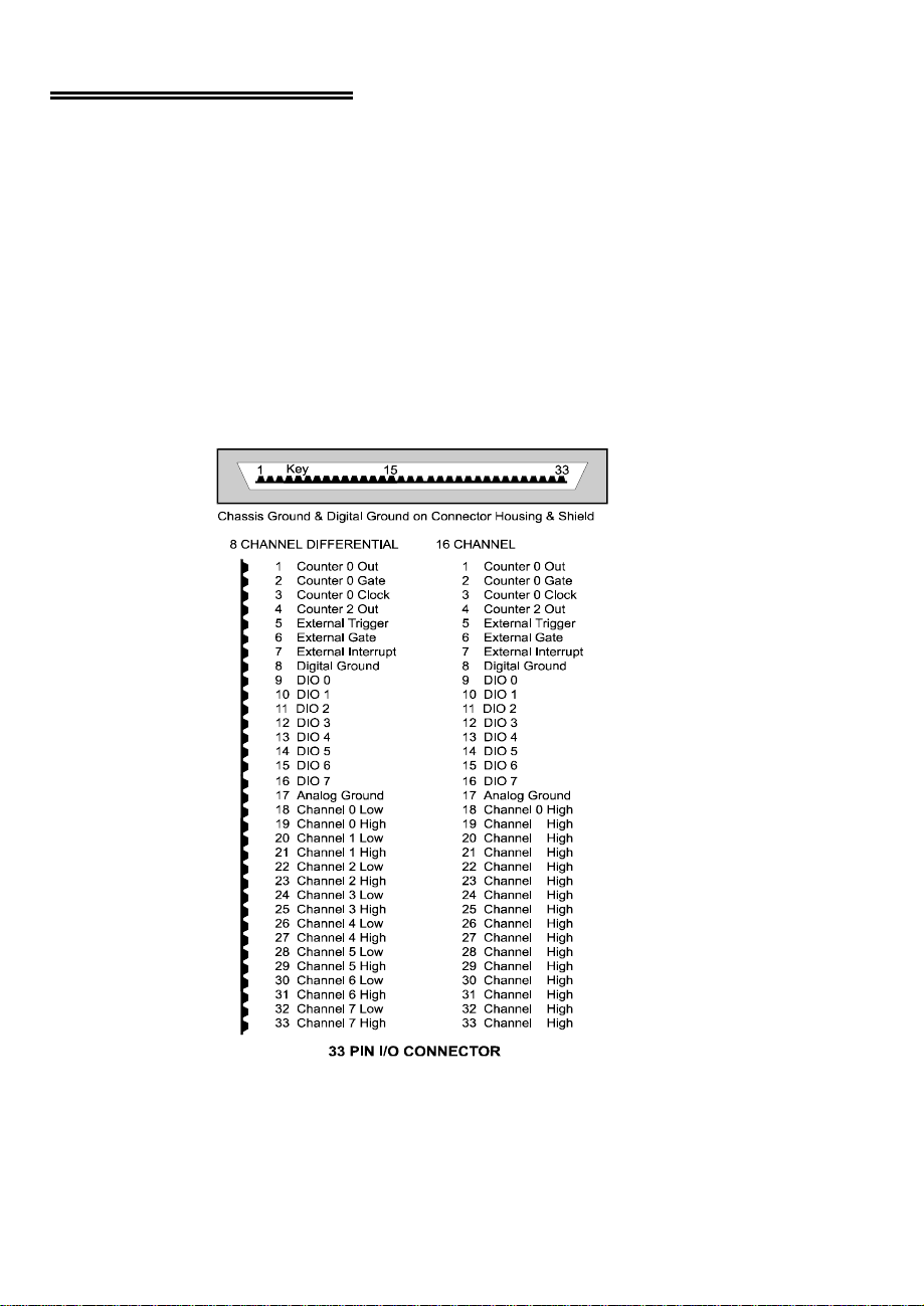
3 I/O CONNECTOR
4
8
14
SINGLE-ENDE D
The PCM-DAS16S/12 has 16 single ended analog inputs. The PCMDAS16D/12 has eight differential inputs. Both boards have an analog
ground, one A/D trigger input, one interrupt input, one gate input, complete
access to one 16-bit counter's clock, gate and output lines, and access to the
A/D pacer's counter output line and eight digital output/inputs. A digital
ground is in the cable shield clips to either side of the 33 pins of the connector as well as one of the connector pins. Please look at the connector diagram
for your board.
Shown here is a PCM-DAS16S/12 and PCM-DAS16D/12 case looking into
the connector which a signal cable or screw terminal box and cable are connected to. The KEY helps to insure that the cable is inserted in the correct
orientation.
1
2
3
4
5
6
7
9
10
11
12
13
15
Page 9

Analog signals should be connected with the high side to the numbered ana-
5
log input and the low side to the low input or the analog ground. Please see
the instructions for single-ended and differential inputs.
Digital signals should not be grounded to the analog ground. Use the cable
shield or the digital ground pin.
Page 10

WARNING
6
Do not exceed the input specifications. There are no socketed or user serviceable parts in a PCM board. Any repair will be expensive.
Analog inputs are limited to +/-15V, unlike the higher ratings of ISA boards.
If you apply a voltage less than -0.5V or greater than 5.5V to a digital input,
you will burn out the transistor.
Please turn now to the table of specifications and familiarize yourself with
them before
connecting any signals.
Page 11

4 ANALOG CONNECTIONS
7
4.1ANALOG INPUTS
Analog signal connection is one of the most challenging aspects of applying a
data acquisition board. If you are an Analog Electrical Engineer then this
section is not for you, but if you are like most PC data acquisition users, the
best way to connect your analog inputs may not be obvious. Though complete
coverage of this topic is well beyond the scope of this manual, the following
section provides some explanations and helpful hints regarding these analog
input connections. This section is designed to help you achieve the optimum
performance from your PCM-DAS16x/12 series board.
Prior to jumping into actual connection schemes, you should have at least a
basic understanding of Single-Ended/Differential inputs and system
grounding/isolation. If you are already comfortable with these concepts you
may wish to skip to the next section (on wiring configurations).
4.1.1 Single-Ended and Differential Inputs
The PCM-DAS16x/12 provides either 8 differential or 16 single-ended input
channels. The concepts of single-ended and differential inputs are discussed
in the following section.
Page 12
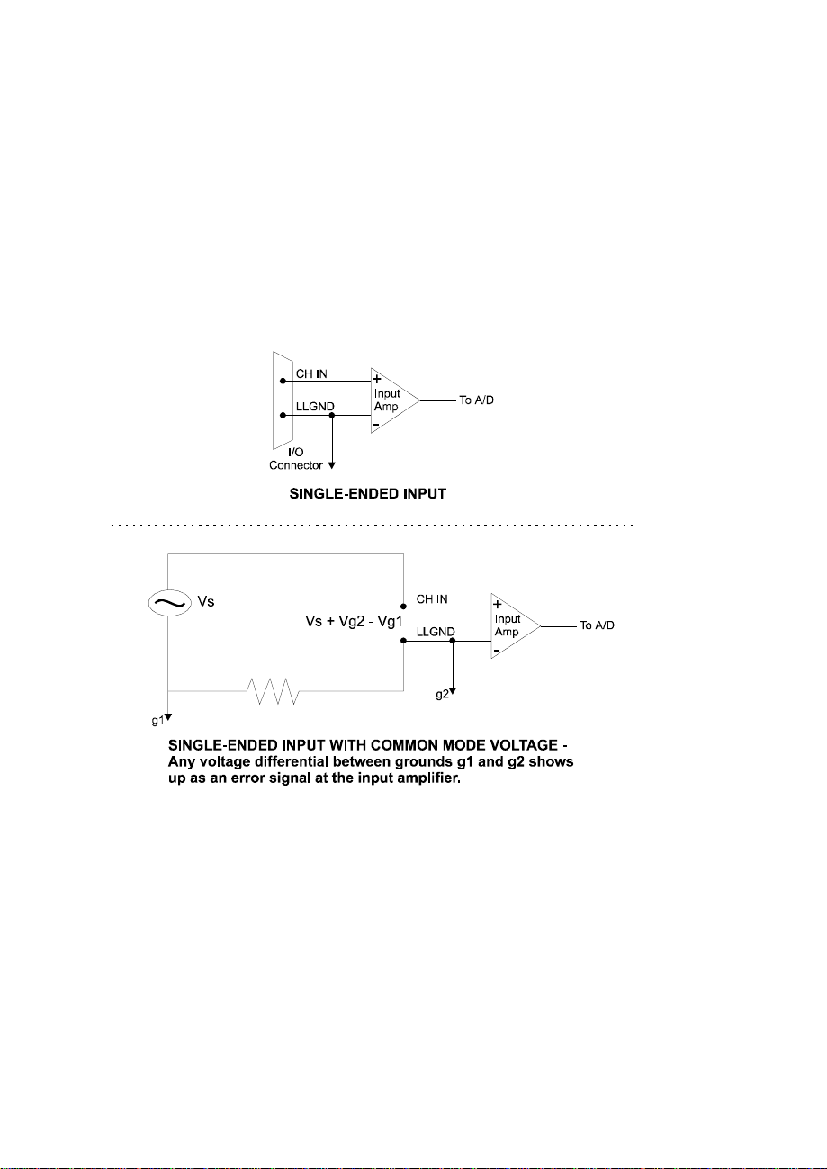
4.1.1 Single-Ended Inputs
8
A single-ended input measures the voltage between the input signal and
ground. In this case, in single-ended mode the PCM-DAS16x/12 measures the
voltage between the input channel and LLGND. The single-ended input configuration requires only one physical connection (wire) per channel and
allows the PCM-DAS16x/12 to monitor more channels than the (2-wire) differential configuration using the same connector and onboard multiplexor.
However, since the PCM-DAS16x/12 is measuring the input voltage relative
to its own low level ground, single-ended inputs are more susceptible to both
EMI (Electro Magnetic Interference) and any ground noise at the signal
source. The following diagrams show the single-ended input configuration.
Page 13
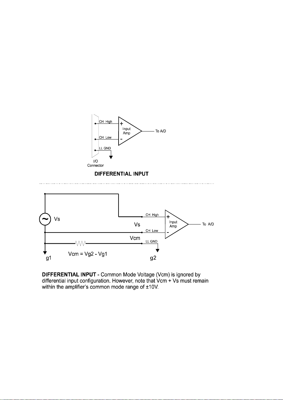
4.1.2 Differential Inputs
9
Differential inputs measure the voltage between two distinct input signals.
Within a certain range (referred to as the common mode range), the measurement is almost independent of signal source to PCM-DAS16x/12 ground
variations. A differential input is also much more immune to EMI than a
single-ended one. Most EMI noise induced in one lead is also induced in the
other, the input only measures the difference between the two leads, and the
EMI common to both is ignored. This effect is a major reason there is twisted
pair wire as the twisting assures that both wires are subject to virtually identical external influence. The diagram below shows a typical differential input
configuration.
Page 14

Before moving on to the discussion of grounding and isolation, it is important
10
Gray area represents common mode range
Both V+ and V- must always remain within
the common mode range relative to LL Gnd
to explain the concepts of common mode, and common mode range (CM
Range). Common mode voltage is depicted in the diagram below as Vcm.
Though differential inputs measure the voltage between two signals, without
(almost) respect to the either signal’s voltages relative to ground, there is a
limit to how far away from ground either signal can go. Though the PCMDAS16x/12 has differential inputs, it will not measure the difference between
100V and 101V as 1 Volt (in fact the 100V would destroy the board!). This
limitation or common mode range is depicted graphically in the following
diagram. The PCM-DAS16x/12 common mode range is +/- 10 Volts. Even in
differential mode, no input signal can be measured if it is more than 10V
from the board’s low level ground (LLGND).
+13V
+12V
+11V
+10V
+9V
+8V
+7V
+6V
+5V
+4V
+3V
+2V
+1V
-1V
-2V
-3V
-4V
-5V
-6V
-7V
-8V
-9V
-10V
-11V
-12V
-13V
With Vcm= +5VDC,
+Vs must be less than +5V, or the common mode range will be exceeded (>+10V)
Vcm
Vcm (Common Mode Voltage) = +5 Volts
4.1.3 System Grounds and Isolation
There are three scenarios possible when connecting your signal source to
your PCM-DAS16x/12 board.
Page 15

1 The PCM-DAS16x/12 and the signal source may have the same (or com-
11
mon) ground. This signal source may be connected directly to the PCMDAS16x/12.
2 The PCM-DAS16x/12 and the signal source may have an offset voltage
between their grounds (AC and/or DC). This offset it commonly referred
to a common mode voltage. Depending on the magnitude of this voltage,
it may or may not be possible to connect the PCM-DAS16x/12 directly to
your signal source. We will discuss this topic further in a later section.
3 The PCM-DAS16x/12 and the signal source may already have isolated
grounds. This signal source may be connected directly to the PCMDAS16x/12.
4.1.4 Which system do you have?
Try the following experiment. Using a battery powered voltmeter1, measure
the voltage (difference) between the ground signal at your signal source and
at your PC. Place one voltmeter probe on the PC ground and the other on the
signal source ground. Measure both the AC and DC Voltages.
If both AC and DC readings are 0.00 volts, you may have a system with common grounds. However, since voltmeters will average out high frequency signals, there is no guarantee. Please refer to the section below titled Common
Grounds.
If you measure reasonably stable AC and DC voltages, your system has an
offset voltage between the grounds category. This offset is referred to as a
Common Mode Voltage. Please be careful to read the following warning and
then proceed to the section describing Common Mode systems.
1
If you do not have access to a voltmeter, skip the experiment and take a look at the following three sec-
tions. You may be able to identify your system type from the descriptions provided.
Page 16

WARNING
12
If either the AC or DC voltage is greater than 10 volts, do
not connect the PCM-DAS16x/12 to this signal source. You
are beyond the boards usable common mode range and will
need to either adjust your grounding system or add special
Isolation signal conditioning to take useful measurements. A
ground offset voltage of more than 30 volts will likely damage the PCM-DAS16x/12 board and possibly your computer.
Note that an offset voltage much greater than 30 volts will
not only damage your electronics, but it may also be hazardous to your health.
This is such an important point, that we will state it again. If
the voltage between the ground of your signal source and
your PC is greater than 10 volts, your board will not take
useful measurements. If this voltage is greater than 30 volts,
it will likely cause damage, and may represent a serious
shock hazard! In this case you will need to either reconfigure
your system to reduce the ground differentials, or purchase
and install special electrical isolation signal conditioning.
If you cannot obtain a reasonably stable DC voltage measurement between
the grounds, or the voltage drifts around considerably, the two grounds are
most likely isolated. The easiest way to check for isolation is to change your
voltmeter to it’s ohm scale and measure the resistance between the two
grounds. It is recommended that you turn both systems off prior to taking this
resistance measurement. If the measured resistance is more than 100 Kohm,
it’s a fairly safe bet that your system has electrically isolated grounds.
4.1.5 Systems with Common Grounds
In the simplest (but perhaps least likely) case, your signal source will have
the same ground as the PCM-DAS16x/12. This would typically occur when
providing power or excitation to your signal source directly from the PCMDAS16x/12. There may be other common ground configurations, but it is
important to note that any voltage between the PCM-DAS16x/12 ground and
your signal ground is a potential error voltage if you set up your system based
on a common ground assumption.
Page 17

As a safe rule of thumb, if your signal source or sensor is not connected
13
directly to an LLGND pin on your PCM-DAS16x/12, it’s best to assume that
you do not have a common ground even if your voltmeter measured 0.0 Volts.
Configure your system as if there is ground offset voltage between the source
and the PCM-DAS16x/12.
4.1.6 Systems with Common Mode (ground offset) Voltages
The most frequently encountered grounding scenario involves grounds that
are somehow connected, but have AC and/or DC offset voltages between the
PCM-DAS16x/12 and signal source grounds. This offset voltage my be AC,
DC or both and may be caused by a wide array of phenomena including EMI
pickup, resistive voltage drops in ground wiring and connections, etc. Ground
offset voltage is a more appropriate term to describe this type of system, but
since our goal is to keep things simple, and help you make appropriate connections, we’ll stick with our somewhat loose usage of the phrase Common
Mode.
4.1.7 Small Common Mode Voltages
If the voltage between the signal source ground and PCM-DAS16x/12 ground
is small, the combination of the ground voltage and input signal will not
exceed the CIO-DAS800’s +/-10V common mode range, (i.e. the voltage
between grounds, added to the maximum input voltage, stays within +/-10V),
This input is compatible with the PCM-DAS16x/12 and the system may be
connected without additional signal conditioning. Fortunately, most systems
will fall in this category and have a small voltage differential between
grounds.
4.1.8 Large Common Mode Voltages
If the ground differential is large enough, boards +/- 10V common mode
range will be exceeded (i.e. the voltage between PCM-DAS16x/12 and signal
source grounds, added to the maximum input voltage you’re trying to measure exceeds +/-10V). In this case the PCM-DAS16x/12 cannot be directly
connected to the signal source. You will need to change your system grounding configuration or add isolation signal conditioning. (Please look at our
ISO-RACK and ISO-5B-series products to add electrical isolation, or give our
technical support group a call to discuss other options).
Page 18

NOTE
14
Relying on the earth prong of a 120VAC for signal ground
connections is not advised.. Different ground plugs may have
large and potentially even dangerous voltage differentials.
Remember that the ground pins on 120VAC outlets on different sides of the room may only be connected in the basement.
This leaves the possibility that the “ground” pins may have a
significant voltage differential (especially if the two 120 VAC
outlets happen to be on different phases!)
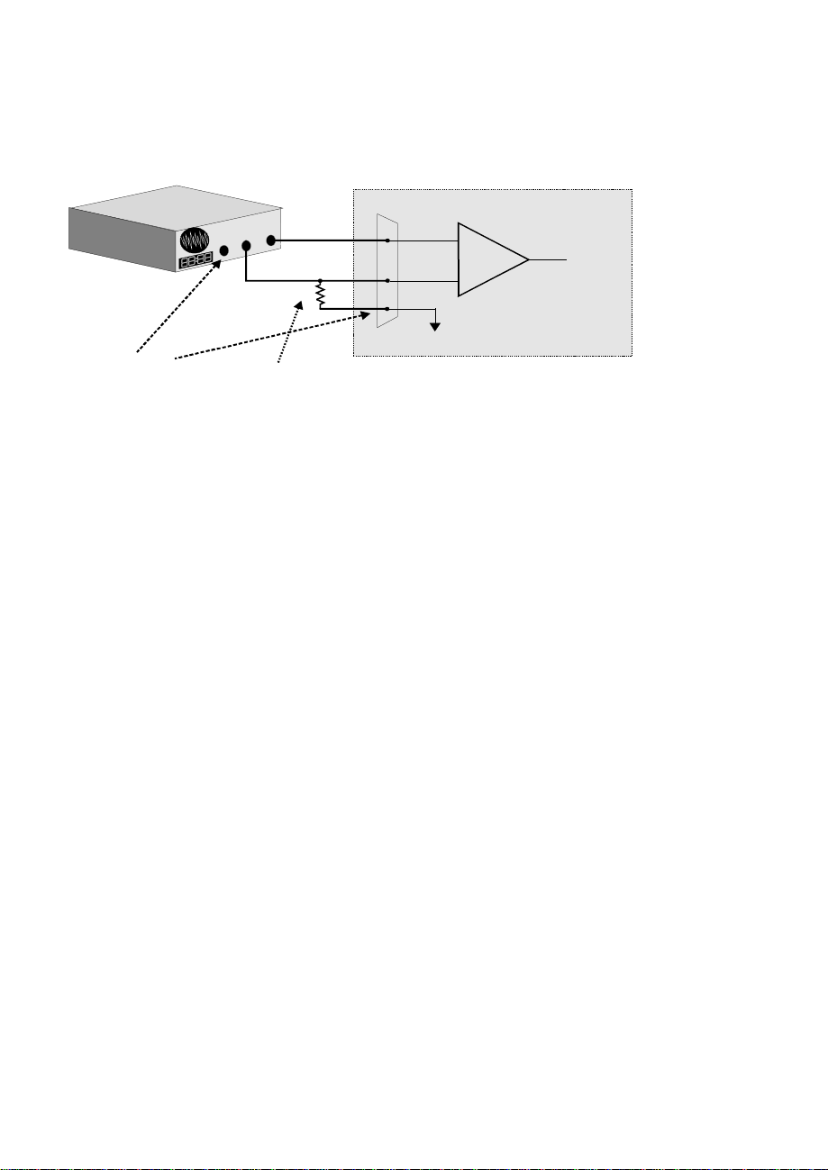
4.1.9 PCM-DAS16x/12 and Signal Source already have Isolated
Grounds
Some signal sources will already be electrically isolated from the PCMDAS16x/12. The diagram below shows a typical isolated ground system.
These signal sources are often battery powered, or are fairly expensive pieces
of equipment (since isolation is not an inexpensive proposition), isolated
ground systems provide excellent performance, but require some extra effort
during connections to assure optimum performance is obtained. Please refer
to the following sections for further details.
Page 19

4.2WIRING CONFIGURATIONS
15
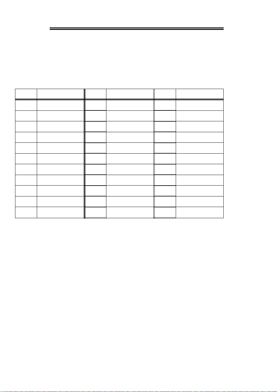
Combining all the grounding and input type possibilities provides us with the following potential connection configurations. The combinations along with our recommendations on usage are shown in the chart below.
GROUND
CATEGORY
Common Mode
Voltage < +/-10V
Common Mode
Voltage < +/-10V
Common Mode
Voltage > +/- 10V
Common Mode
Voltage > +/-10V
Already Isolated
Grounds
Already Isolated
Grounds
INPUT
OUR VIEW
CONFIGURATION
RecommendedSingle-Ended InputsCommon Ground
AcceptableDifferential InputsCommon Ground
Not RecommendedSingle-Ended Inputs
RecommendedDifferential Inputs
Unacceptable without
Single-Ended Inputs
adding Isolation
Unacceptable without
Differential Inputs
adding Isolation
AcceptableSingle-ended Inputs
RecommendedDifferential Inputs
The following sections depicts recommended input wiring schemes for each of the 8
possible input configuration/ grounding combinations.
4.2.1 Common Ground / Single-Ended Inputs
Single-ended is the recommended configuration for common ground connections.
However, if some of your inputs are common ground and some are not, we recommend you use the differential mode. There is no performance penalty (other than loss
of channels) for using a differ ential inp ut to measure a common ground signal sour ce.
Page 20

However the reverse is not true. The diagram below shows a recommended connec-
16
+
-
Input
To A /D
A/D Board
I/O
Connector
+
-
Input
To A / D
A/D Board
I/O
Connector
sharing common ground connected
tion diagram for a common ground / single-ended input system.
l
a
h
n
t
i
g
i
w
S
c
r
u
o
S
C
d
e
n
G
n
o
m
m
o
Optional wire
since signal source
and A/D board share
common ground
-
+
CH IN
LL GND
Amp
Signal source and A/D board
sharing common ground connected
to single-ended input.
4.2.2 Common Ground / Differential Inputs
The use of differential inputs to monitor a signal source with a common ground is a
acceptable configuration though it requires more wiring and offers fewer channels
than selecting a single-ended configuration. The diagram below shows the recommended connections in this configuration.
l
a
n
h
t
g
i
wi
S
c
r
u
o
S
Co
d
e
n
G
n
o
m
m
Optional wire
since signa l source
and A/D board share
common ground
+
-
Required connection
of LL GND to CH Low
Signal source and A/D board
to differential input.
CH High
CH Low
LL GND
Amp
4.2.3 Common Mode Voltage < ±10V / Single Ended Inputs
This is not a re commended configuration. In fact, the phrase common mode has no
meaning in a single-ended system and this case would be better described as a system
with offset grounds. Anyway, you are welcome to try this configuration, no system
Page 21

damage should occur and depending on the overall accuracy you require, you may
17
+
-
Input
To A /D
A/D Board
I/O
Connector
S
I/O
Connector
+
-
Input
To A /D
A/D Board
L
a
Isolation
e
c
r
u
So
l
a
n
g
i
t
i
w
n
o
m
m
o
e
g
C
a
t
h
l
o
V
e
d
o
M
The voltage differential
between these grounds,
added to the maximum
input signal must st ay
within +/-10V
GND
+
-
CH High
CH Low
LL GND
Amp
Signal source and A/D board
with common mode voltage
connected to a differential input.
receive acceptable results.
4.2.4 Common Mode Voltage < ±10V /Differential Inputs
Systems with varying ground potentials should always be monitored in the differential
mode. Care is required to assure that the sum of the input signal and the ground differential (referred to as the common mode voltage) does not exceed the common mode
range of the A/D board (+/-10V on the PCM-DAS16x/12). The diagram below show
recommended connections in this configuration.
n
o
m
m
o
c
e
e
g
g
r
a
t
l
l
o
a
v
e
d
s
o
n
m
e
e
w
t
e
b
e
c
r
u
o
s
When the voltage difference
between signal source and
A/D board ground is large
enough so the A/D board’s
common mode range is
exceeded, isolat ed signal
conditioning must be added.
d
n
r
g
a
i
o
b
D
/
A
&
GND
+
-
Barrier
CH IN
LL GND
Amp
System with a Large Common Mode Voltage,
Connected to a Single-Ended Input
4.2.5 Common Mode Voltage > +/-10V
The PCM-DAS16x/12 will not directly monitor signals with common mode voltages
greater than +/-10V. You will either need to alter the system ground configuration to
Page 22

reduce the overall common mode voltage, or add isolated signal conditioning between
18
a
Isolation
+
-
Input
To A /D
A/D Board
I/O
Connector
10K is a recommended value. You may short LL GND to CH Low
instead, but this will reduce your system’s noise immunity.
I/O
Connector
+
-
Input
To A /D
A/D Board
I
n
o
m
m
o
c
e
e
g
r
g
a
t
l
L
e
d
o
m
b
o
l
v
a
n
g
i
s
n
e
e
/
w
t
A
e
&
e
c
r
u
o
s
GND
When the vol tage difference
between signal source and
A/D board ground is large
enough so the A/D board’s
common mode ra nge is
exceeded, isolated signal
conditioning must be added.
d
r
a
o
b
D
-
Barrier
+
10 K
CH High
CH Low
LL GND
Amp
System with a Large Common Mode Voltage,
Connected to a Differential Input
the source and your board.
4.2.6 Isolated Grounds / Single-Ended Inputs
Single-ended inputs can be used to monitor iso lated inputs, tho ugh the use of the differential mode will increase you system’s noise immunity. The diagram below shows
the recommended connections is this configuration.
d
e
t
a
l
o
s
l
a
n
g
i
s
e
c
r
u
o
s
+
-
CH IN
Connected to a Single-Ended Input
LL GND
Isolated Signal Source
Amp
Page 23
4.2.7 Isolated Grounds / Differential Inputs
19
+
-
Input
To A /D
A/D Board
I/O
Connector
S
10K is a recommended value. Y o u ma y short LL GND to CH Low
instead, but this will reduce your system’s noise immunity.
Optimum performance with isolated signal sources is assured with the use of the differential input setting. The diagram below shows the recommend connections is this
configuration..
e
c
r
u
o
S
l
a
n
g
i
d
n
a
These grounds are
electrically isolated.
d
r
a
o
B
D
/
A
d
a
e
r
l
A
.
d
e
t
a
l
o
s
I
y
GND
+
-
10 K
Already isolated signal source
and A/D board connected to
a differential input.
CH High
CH Low
LL GND
Amp
Page 24

5 PROGRAMMING & APPLICATIONS
20
Your PCM-DAS16x/12 is now installed and ready for use. Although the
PCM-DAS16x/12 is part of the larger DAS16 family, there is no correspondence between registers. Software written at the register level for the other
DAS16's will not work with the PCM-DAS16x/12.
5.1PROGRAMMING LANGUAGES
The Universal Library provides complete access to the PCM-DAS16x/12
functions from a range of programming languages; both DOS and Windows.
If you are planning to write programs, or would like to run the example programs for Visual Basic or any other language, please turn now to the Universal Library manual.
5.2PACKAGED APPLICATIONS PROGRAMS
Many packaged application programs, such as Labtech Notebook now have
drivers for the PCM-DAS16x/12. If the package you own does not appear to
have drivers for the PCM-DAS16x/12 please fax the package name and the
revision number from the install disks. We will research the package for you
and advise by return fax how to obtain PCM-DAS16x/12 drivers.
Page 25

6 CALIBRATION
21
The PCM-DAS16x/12 is calibrated via software. The case may not be
opened and there are no parts inside which you can service. There are no
socketed components.
The PCM-DAS16x/12 should not need re-calibration more frequently than
once every six months. You can check the calibration of offset and gain at
any time with InstaCal.
6.1 SOFTWARE CALIBRATION
If you are using the Universal Library, you can set software calibration factors for offset and gain using the Calibration option of InstaCal. These factors will be applied to readings made by any of the A/D routines called from
any of the language libraries of Universal Library.
The calibration factors are stored in the on-board EEPROM. Of course, the
calibration factors may be recalculated at any time by running InstaCal calibration.
Choose Calibration from the InstaCal menu, and follow the instructions.
Press F1 for help.
Page 26

7 I/O ADDRESS MAP & REGISTER FUNCTIONS
22
A base address register controls the beginning, or 'Base Address' of the I/O
addresses occupied by the control registers of the PCM-DAS16x/12. In all,
16 addresses are occupied. The base address is assigned by PCMCIA Card
and Socket Services (CSS), read by InstaCal and stored in the CB.CFG file
installed in your computer. Please read about installing and using InstaCal.
7.1CONTROL REGISTERS
Once CSS is installed and a base address has been established, the PCMDAS16x/12 may be controlled by writing to and reading from the control registers. While it is possible to write your own control routines for the
PCM-DAS16x/12, routines have been written and are available in ComputerBoards' Universal Library for DOS and Windows programming languages.
NOTE ON REGISTER PROGRAMMING SUPPORT
While the complete register map is summarized here, only very limited support for assembly language or direct register programming is available. Register level programming should only be attempted by experienced
programmers. We support the use of the PCM-DAS16x/12 through high
level languages using Universal Library and the example programs provided.
Major functions of the control registers:
I/O ADDRESS PCM-DAS16x/12 FUNCTION R | W
BASE + 0 A/D Data & Channel | Start A/D
BASE + 2 Digital In|Out & Channel Scan Limits
BASE + 4 Interrupt Control & Status
BASE + 6 Input Range and Trigger Method
BASE + 8 Counter 0 Read | Load
BASE + A Counter 1 Read | Load
Page 27

BASE + C Counter 2 Read | Load
23
BASE + E None | Counter Control
Interrupt Source Control
The interrupt source is controlled by three bits.
INT2 INT1 INT0 Source
001Pacer - Counter 2
010External - Pin 7
011FIFO Not Empty
100FIFO Half Full
101End of Channel Scan
The A/D trigger source is controlled by two bits.
TS1 TS0 Source
0 X Software Trigger
1 0 Rising Trigger Input, Pin 5
1 1 Pacer - Counter 2
The range of analog input is set by 4 bits.
G3 G2 G1 G0 Range
1000+/- 10 V
0000+/- 5 V (A/D Std.)
0001+/- 2.5 V
0010+/- 1.25 V
01000 to 10 V
Page 28

01010 to 5 V
24
01100 to 2.5 V
01110 to 1.25 V
The digital I/O lines may be set as follows via 2 control bits.
UDIR LDIR Bits 7:4 Bits 3:0
0 0 Input Input
0 1 Input Output
1 0 Output Input
1 1 Output Output
Page 29
8 CABLE & SCREW TERMINAL BOARD
25
The PCM-C37/33 is a 10 inch 33 conductor cable assembly for use with 33
pin PCMCIA cards. The PCM-C37/33 has a connector on one end and a 37
pin D type connector at the other. The chart below describes the color coding
of the wires for each of the 33 pins.
COLORPINCOLORPINCOLORPIN
Yellow23White/Black12Black1
Grey24White/Grey13Red2
Pink25Red/Blue14Brown3
Blue/White26Red/Orange15Orange4
Brown/White27Orange/Red16Violet5
Orange/White28Red/Green17Tan6
Green/White29Green/Red18White/Blue7
Red/White30Green/Yellow19White/Brown8
Black/White31White20White/Orange9
Grey/White32Green21White/Green10
Blue/Red33Blue22White/Red11
If you want to wire directly to your signal source, simply cut off the 37 pin
connector and wire up the signals using the color to pin number guide above.
If you wish to use a screw terminal board, please purchase a CIO-MINI37 and
connect it to the 37 pin connector end of the cable. Of course pins 34 to 37
will not have any function. Use the PCM-DAS16x/12 connector diagram
elsewhere in this manual to determine the function of the signals at the screw
terminals. The screw terminals are numbered 1 to 37, and the cable is wired
so pin 1 of the PCM board connects to pin 1 of the screw terminal, and so on.
Page 30

9 SPECIFICATIONS
26
Typical for 25OC unless otherwise specified.
POWER CONSUMPTION
+5V quiescent 65 mA typical, 90 mA max
+5V during CIS read 75 mA typical, 110 mA max
ANALOG INPUT SECTION
A/D convertor type ADS7804
Resolution 12 bits
Programmable ranges ±10V, ±5V, ±2.5V, ±1.25V, 0-10V,
0-5V, 0-2.5V, 0-1.25V
A/D pacing Programmable: internal counter
or external source (Ext Trig/Clk)
or software polled
A/D Trigger sources External polled gate trigger (Ext
Trig/Clk)
A/D Triggering Modes:
Digital: Gated pacer, software polled.
(Gate must be disabled by software after trigger event.)
Data transfer From 512 sample FIFO via
REPINSW, interrupt or software
polled
Polarity Bipolar, Unipolar
Number of channels:
PCM-DAS16D/12 8 Differential
PCM-DAS16S/12 16 Single ended
A/D conversion time 10 µs
Page 31

Throughput (post-process calibration) 100k samples/sec
27
Relative Accuracy (software calibrated) ±1 LSB
Differential Linearity error ±1 LSB
Integral Linearity ±1 LSB
Gain drift (A/D specs) 160 ppm/°C
Zero drift (A/D specs) 150 ppm/°C
Common Mode Range:
PCM-DAS16D/12 ±10V
CMRR @ 60Hz:
PCM-DAS16D/12 −72 dB
Input leakage current ±20 nA
Input impedance 10 Mohms min
Absolute maximum input voltage ±15V
DIGITAL SECTION
Digital type FPGA
Configuration Two ports, four bits each. Pro-
grammable as 8 input / 8 output
or 4 input / 4 output
Input low voltage 0.8V max
Input high voltage 2.0V min
Output low voltage (IOL = 4mA) 0.32V max
Output high voltage (IOH = -4mA) 3.86V min
Absolute maximum input voltage −0.5V , +5.5V
Interrupts Programmable: levels 2 - 15
Interrupt enable Programmable
Interrupt sources End-of-conversion, FIFO-half-full,
external (Ext Int)
Page 32

COUNTER SECTION
28
Counter type 82C54
Configuration 3 down counters, 16 bits each
Counter 0 - User counter 1
Source: Programmable external (Ctr 1 Clk)
or 100kHz internal source
Gate: Available at connector (Ctr 1 Gate)
Output: Available at connector (Ctr 1 Out)
Counter 1 - ADC Pacer Lower Divider
Source: Programmable, 1MHz or 10 MHz
internal source
Gate: Available at connector (Ctr 2 Gate),
pulled to logic high through 10k
resistor
Output: Chained to Counter 2 Clock
Counter 2 - ADC Pacer Upper Divider
Source: Counter 1 Output
Gate: Programmable, external (Ext
Trig/Clk) or Not Connected (pulled
high through 10k resistor)
Output: Programmable as ADC Pacer clock,
hard-wired to user connector (Ctr 3
Out)
Clock input frequency 10 Mhz max
High pulse width (clock input) 30 ns min
Low pulse width (clock input) 50 ns min
Gate width high 50 ns min
Gate width low 50 ns min
Input low voltage 0.8V max
Page 33

Input high voltage 2.0V min
29
Output low voltage 0.4V max
Output high voltage 3.0V min
Crystal Oscillator:
Frequency 10 MHz
Frequency accuracy 100 ppm
ENVIRONMENT
Operating temperature range 0 to 70°C
Storage temperature range −40 to 100°C
Humidity 0 to 90% non-condensing
Page 34

30
Page 35

EC Declaration of Conformity
A
We, ComputerBoards, Inc., declare under sole responsibility that the product:
PCMCI
DescriptionPart Number
to which this declaration relates, meets the essential requirements, is in conformity
with, and CE marking has been applied according to the relevant EC Directives listed
below using the releva nt section of the fol l owing EC standards and other normative
documents:
EU EMC Directive 89/336/EEC: Essential requirements relating to electromagnetic
compatibility.
EU 55022 Class B: Limits and methods of measurements of radio interference
characteristics of information technology equipment.
EN 50082-1: EC generic immunity requirements.
IEC 801-2: Electrostatic discharge requirements for industrial process measurement
and control equipment.
Analog Input BoardPCM-DAS16x/12
IEC 801-3: Radiated electromagnetic field requirements for industrial process
measurements and control equipment.
IEC 801-4: Electrically fast transients for industrial process measurement and control
equipment.
Carl Haapaoja, Director of Quality Assurance
Page 36

ComputerBoards, Inc.
16 Commerce Boulevard
Middleboro, MA 02346
Tel: (508) 946-5100
Fax: (508)946-9500
www.computerboards.com
 Loading...