

Page 1

CIO-TERM100
g
&
CIO-TERM100/DST
User’s Manual
Revision 1
March, 2001
©
Copyri
ht 2001, Measurement Computing Corporation
Page 2

Your new Measurement Computing product comes with a fantastic extra —
Management committed to your satisfaction!
Thank you for choosing a Measurement Computing product—and congratulations! You own the finest, and you can now enjoy
the protection of the most comprehensive warranties and unmatched phone tech support. It’s the embodiment of our mission:
To provide data acquisition hardware and software that will save time and save money.
Simple installations minimize the time between setting up your system and actually making measurements. We offer quick and
simple access to outstanding live FREE technical support to help integrate MCC products into a DAQ system.
Limited Lifetime Warranty: Most MCC products are covered by a limited lifetime warranty against defects in materials or
workmanship for the life of the product, to the original purchaser, unless otherwise noted. Any products found to be defective in
material or workmanship will be repaired, replaced with same or similar device, or refunded at MCC’s discretion. For specific
information, please refer to the terms and conditions of sale.
Harsh Environment Program: Any Measurement Computing product that is damaged due to misuse, or any reason, may be
eligible for replacement with the same or similar device for 50% of the current list price. I/O boards face some harsh
environments, some harsher than the boards are designed to withstand. Contact MCC to determine your product’s eligibility for
this program.
30 Day Money-Back Guarantee: Any Measurement Computing Corporation product may be returned within 30 days of
purchase for a full refund of the price paid for the product being returned. If you are not satisfied, or chose the wrong product by
mistake, you do not have to keep it.
These warranties are in lieu of all other warranties, expressed or implied, including any implied warranty of merchantability or
fitness for a particular application. The remedies provided herein are the buyer’s sole and exclusive remedies. Neither
Measurement Computing Corporation, nor its employees shall be liable for any direct or indirect, special, incidental or
consequential damage arising from the use of its products, even if Measurement Computing Corporation has been notified in
advance of the possibility of such damages.
Trademark and Copyright Information
Measurement Computing Corporation, InstaCal, Universal Library, and the Measurement Computing logo are either trademarks
or registered trademarks of Measurement Computing Corporation. Refer to the Copyrights & Trademarks section on
mccdaq.com/legal
mentioned herein are trademarks or trade names of their respective companies.
© 2001 Measurement Computing Corporation. All rights reserved. No part of this publication may be reproduced, stored in a
retrieval system, or transmitted, in any form by any means, electronic, mechanical, by photocopying, recording, or otherwise
without the prior written permission of Measurement Computing Corporation.
Notice
Measurement Computing Corporation does not authorize any Measurement Computing Corporation product for use
in life support systems and/or devices without prior written consent from Measurement Computing Corporation.
Life support devices/systems are devices or systems that, a) are intended for surgical implantation into the body, or
b) support or sustain life and whose failure to perform can be reasonably expected to result in injury. Measurement
Computing Corporation products are not designed with the components required, and are not subject to the testing
required to ensure a level of reliability suitable for the treatment and diagnosis of people.
for more information about Measurement Computing trademarks. Other product and company names
HM CIO-TERM100_DST.lwp
Page 3
1 INTRODUCTION & PHYSICAL DESCRIPTION
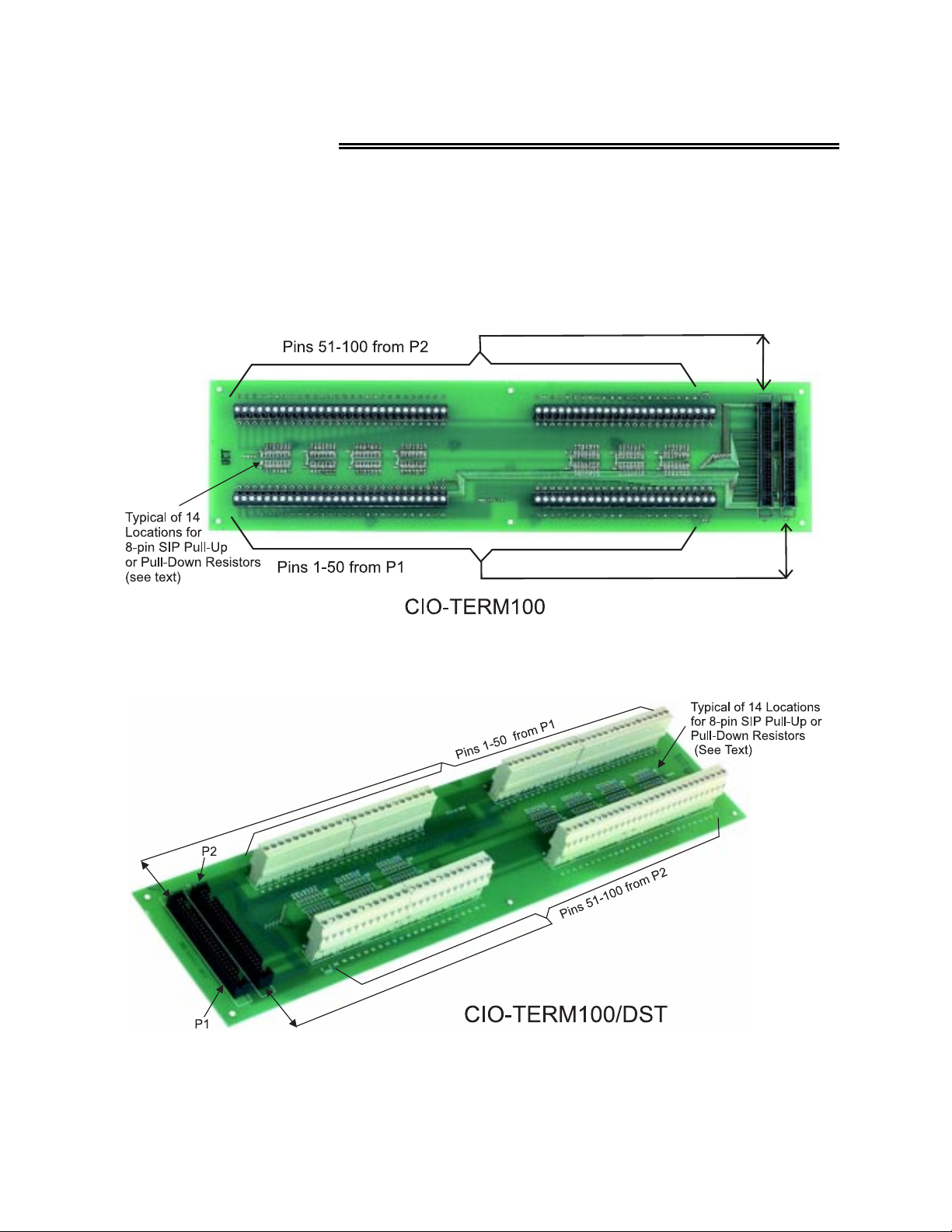
The CIO-TERM100 and its variant CIO-TERM100/DST are 100-pin screw terminal boards intended for
use with high-density digital I/O boards. Each has two, 50-pin male IDC connectors that accept our
C50FF-# cables. The screw terminals will accept 12 to 22 AWG wire. See Figures 1-1 and 1-2 for board
connector vs. terminal strip layouts.
Figure 1-1. CIO-TERM100 Board Layout
Figure 1-2. CIO-TERM100/DST Board Layout
1
Page 4

The board has 14 open mounting positions where 8-pin, 7-resistor Single Inline Packages (SIPs) can be
installed when pull-up (or pull-down) resistors are necessary or desirable. The common terminals on the
SIPs are all common to each other on the board. The board connection point is labeled “POWER”.
Thus, if the POWER point on the board is tied to +5VDC, any SIP installed and jumper-wired to screw
terminals will have those pins pulled high (Figure 1-3).
Alternatively, if the POWER point is tied to Ground, any (and all) installed SIPs resistors will pull their
associated screw terminals to ground.
We recommend using 2.2Kohm resistors for pull-up or pull-down. You can obtain these from us: the part
number is 2.2K*7PU.
NOTE: SIPs are not connected to screw terminals by board etch. After a SIP is installed, you must
install jumpers to each resistor from the screw terminals as required.
Figure 1-3. SIP Installation
Most boards that you would use this terminal board with have SIP locations also. Either location can be
used with equal efficiency. However, it can be useful to have both. If one or m ore digital lines do not
require termination, there is an adv antage to using the resistor locations on the CI O-TERM100 since the
resistors are individually jumpered to each digital IO line.
If you are unfamiliar with pull-up/pull-down resistor theory, refer to the manual for the Digital I/O board.
See Figure 1-4 and 1-5 for schematics of the CIO-TERM100 and CIO-TERM100/DST terminal boards.
2
Page 5
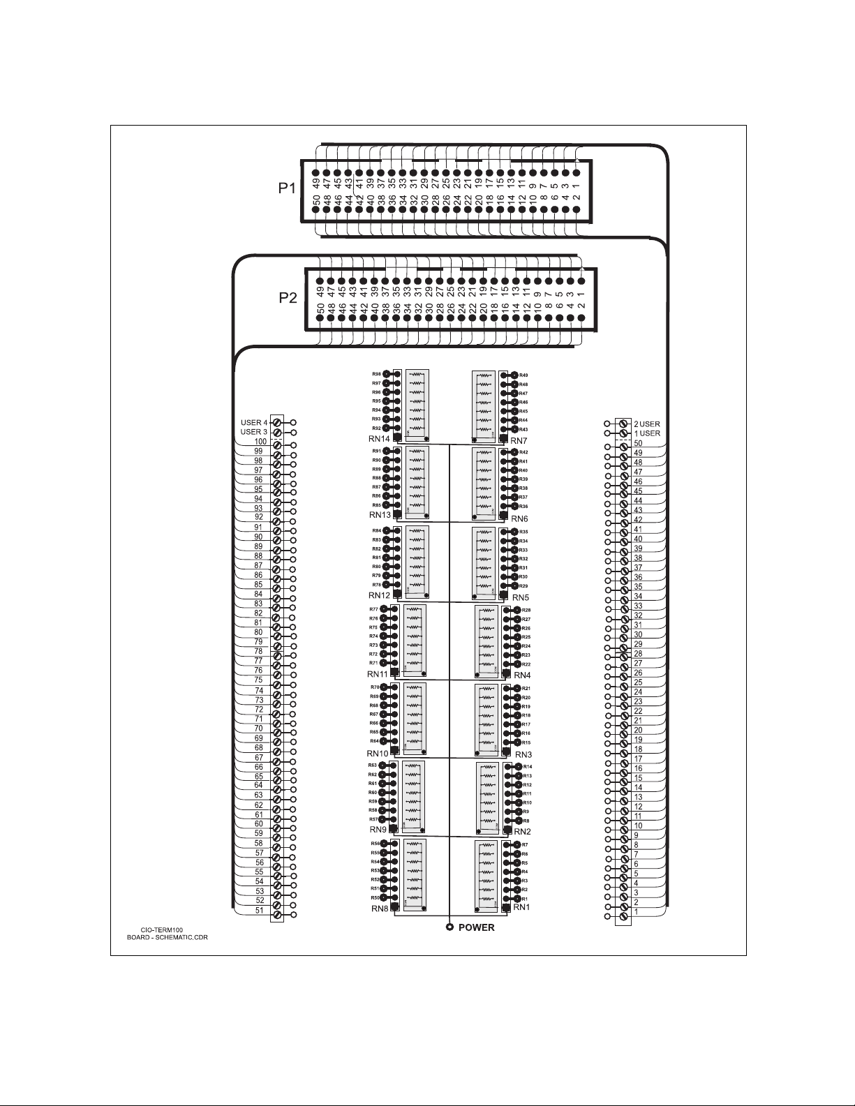
Figure 1-4. CIO-TERM100 Schematic
3
Page 6
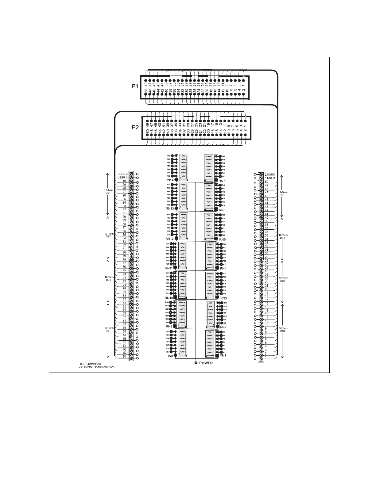
Figure 1-5. CIO-TERM100/DST Schematic
4
Page 7

EC Declaration of Conformity
We, Measurement Computing Corp., declare under sole responsibility that the product:
CIO-TERM100
CIO-TERM100/DST
to which this declaration relates, meets the essential requirements, is in conformity with, and CE marking has been
applied according to the relevant EC Directives listed below using the relevant section of the following EC standards
and other normative documents:
EU EMC Directive 89/336/EEC
EU 55022 Class B
technology equipment.
EN 50082-1
IEC 801-2
IEC 801-3
equipment.
IEC 801-4
Carl Haapaoja, Director of Quality Assurance
: Electrostatic discharge requirements for industrial process measurement and control equipment.
: Radiated electromagnetic field requirements for industrial process measurements and control
: Electrically fast transients for industrial process measurement and control equipment.
: Limits and methods of measurements of radio interference characteristics of information
: EC generic immunity requirements.
Screw Terminal Board
Screw Terminal Board with Detachable Screw Terminals
DescriptionPart Number
: Essential requirements relating to electromagnetic compatibility.
Page 8

Measurement Computing Corporation
10 Commerce Way
Suite 1008
Norton, Massachusetts 02766
(508) 946-5100
Fax: (508) 946-9500
E-mail: info@mccdaq.com
www.mccdaq.com
 Loading...